Air standard Cycle
Aim: To solve an otto cycle, to create its PV diagram and find the cycle efficiency
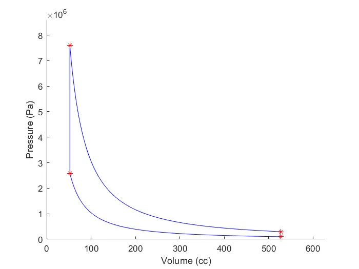
Theory: Otto cycle is a constant volume heat addition cycle which forms the basis for working of today's spark ignition engines. The process 1`->`2 represents isentropic compression of air as piston moves from BDC to TDC. During process 2`->`3 heat is supplied at constant volume, this process corresponds to spark ignition and combustion in the actual engine. Process 3`->`4 represents isentropic expansion of air as piston moves from TDC to BDC. Finally process 4`->`1 represent heat rejection at constant volume.
The program code is as follows,
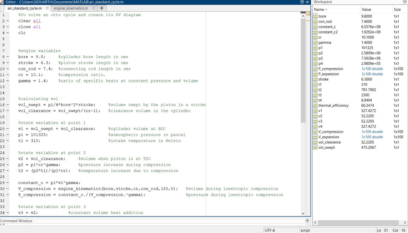
%To solve an otto cycle and create its PV diagram
clear all
close all
clc


%engine variables
bore = 9.8;     %cylinder bore length in cms
stroke = 6.3;   %piston stroke length in cms
con_rod = 7.4;  %connecting rod length in cms
cr = 10.1;      %compression ratio,
gamma = 1.4;    %ratio of specific heats at constant pressure and volume


%calculating vol
vol_swept = pi/4*bore^2*stroke;     %volume swept by the piston in a stroke
vol_clearance = vol_swept/(cr-1);   %clearance volume in the cylinder

%state variables at point 1
v1 = vol_swept + vol_clearance;     %cylinder volume at BDC
p1 = 101325;                        %atmospheric pressure in pascal
t1 = 310;                           %intake temperature in Kelvin

%state variables at point 2
v2 = vol_clearance;     %volume when piston is at TDC
p2 = p1*cr^gamma;       %pressure increase during compression
t2 = (p2*t1)/(p1*cr);   %temperature increase due to compression

constant_c = p1*v1^gamma;
V_compression = engine_kinematics(bore,stroke,cr,con_rod,180,0);   %volume during isentropic compression
P_compression = constant_c./(V_compression.^gamma);                %pressure during isentropic compression

%state variables at point 3
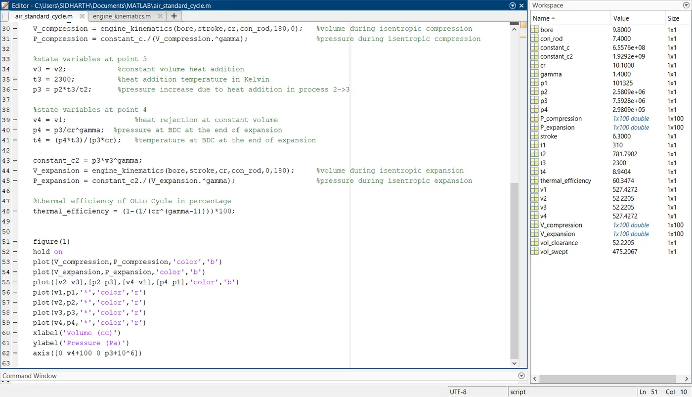
v3 = v2;            %constant volume heat addition
t3 = 2300;          %heat addition temperature in Kelvin
p3 = p2*t3/t2;      %pressure increase due to heat addition in process 2->3

%state variables at point 4
v4 = v1;                %heat rejection at constant volume
p4 = p3/cr^gamma;  %pressure at BDC at the end of expansion
t4 = (p4*t3)/(p3*cr);   %temperature at BDC at the end of expansion

constant_c2 = p3*v3^gamma;
V_expansion = engine_kinematics(bore,stroke,cr,con_rod,0,180);     %volume during isentropic expansion
P_expansion = constant_c2./(V_expansion.^gamma);                   %pressure during isentropic expansion

%thermal efficiency of Otto Cycle in percentage
thermal_efficiency = (1-(1/(cr^(gamma-1))))*100;


figure(1)
hold on
plot(V_compression,P_compression,'color','b')
plot(V_expansion,P_expansion,'color','b')
plot([v2 v3],[p2 p3],[v4 v1],[p4 p1],'color','b')
plot(v1,p1,'*','color','r')
plot(v2,p2,'*','color','r')
plot(v3,p3,'*','color','r')
plot(v4,p4,'*','color','r')
xlabel('Volume (cc)')
ylabel('Pressure (Pa)')
axis([0 v4+100 0 p3+10^6])
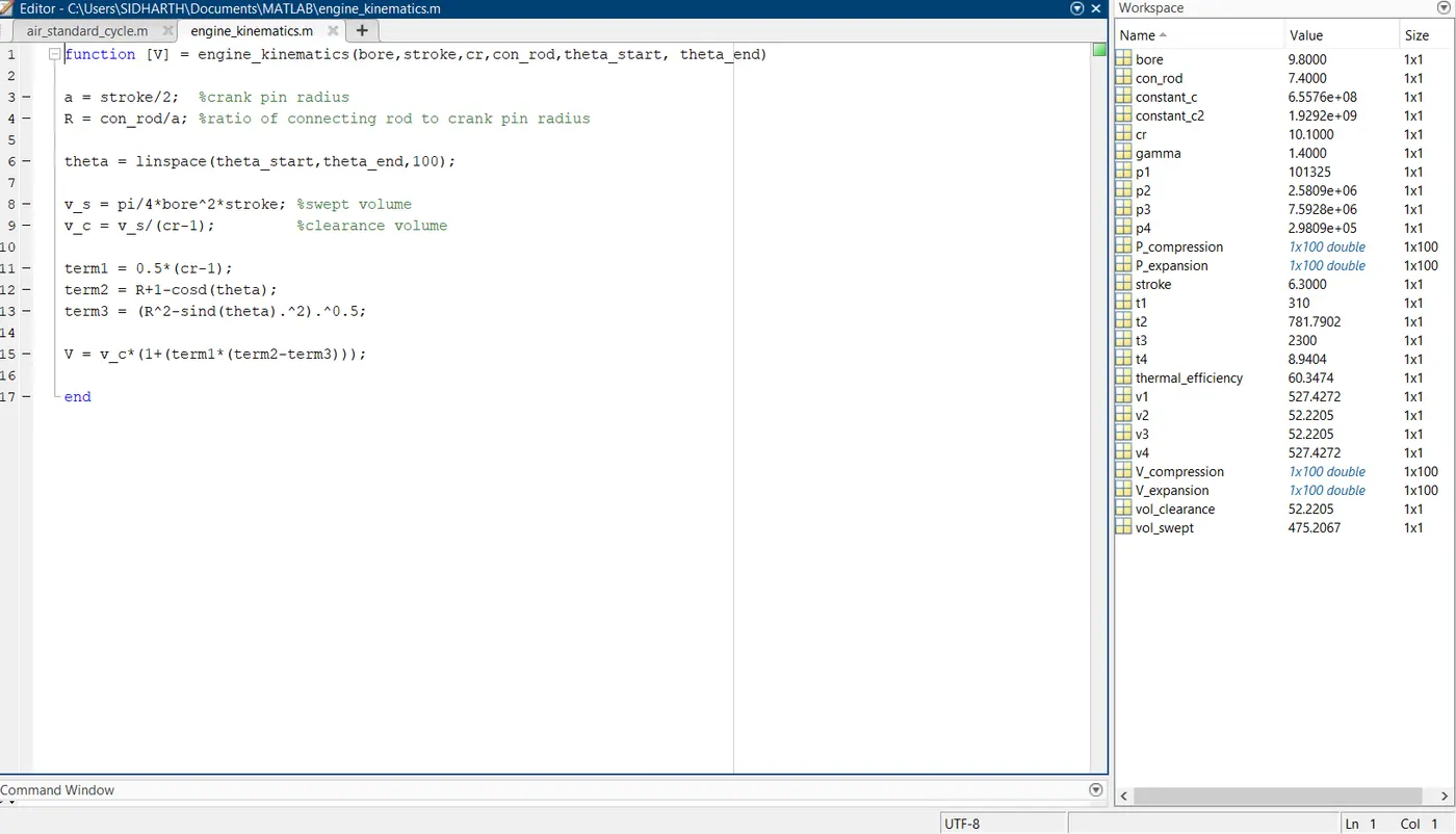
'engine_kinematics' function code is shown below,
function [V] = engine_kinematics(bore,stroke,cr,con_rod,theta_start, theta_end)

a = stroke/2;  %crank pin radius
R = con_rod/a; %ratio of connecting rod to crank pin radius

theta = linspace(theta_start,theta_end,100);

v_s = pi/4*bore^2*stroke; %swept volume
v_c = v_s/(cr-1);         %clearance volume

term1 = 0.5*(cr-1);
term2 = R+1-cosd(theta);
term3 = (R^2-sind(theta).^2).^0.5;

V = v_c*(1+(term1*(term2-term3)));

end
PV diagram obtained is shown below,
Explanation:
Total cylinder volume = swept volume `(V_s)` + clearance volume `(V_c)`
`V_s` = `pi/4`*bore^2*stroke
Compression Ratio, `cr` = Total cylinder volume / clearance volume
`cr = (V_s + V_c)/V_c`
`implies cr = V_s/V_c + 1`
`implies cr - 1 = V_s/V_c`
`implies V_c = V_s/(cr-1)`
`V_1` and `V_4` are the cylinder volume at BDC
`V_2` and `V_3` are the cylinder volume at TDC
At point 1,
`P_1` is at atmospheric pressure
`V_1` is `V_s + V_c`
`T_1` is the intake temperature
At point 2,
`P_1*V_1^gamma = P_2*V_2^gamma`
also, `V_1/V_2 = cr` , compression ratio
`therefore P_2 = P_1*cr^gamma`
`(P_1*V_1)/T_1 = (P_2*V_2)/T_2`
`implies T_2 = (P_2*V_2*T_1)/(P_1*V_1)`
`therefore T_2 = (P_2*T_1)/(P_1*cr)`
At point 3,
`V_3 = V_2` , Volume remains a constant
`T_3` is the peak temperature rise
Pressure rise at constant volume is given by,
`P_3/T_3 = P_2/T_2`
`therefore P_3 = (P_2*T_3)/T_2`
At point 4,
`V_4 = V_1` , Volume remains a constant
`P_4*V_4^gamma = P_3*V_3^gamma`
`V_4/V_3 = cr`
`implies P_4 = P_3*(V_3/V_4)^gamma`
`implies P_4 = P_3*(1/(cr^gamma))`
`therefore P_4 = P_3/(cr^gamma)`
Thermal efficiency is given by `eta_(thermal) = (Q_s - Q_r)/Q_s`
Where,
`Q_s` = Heat Supplied
`Q_r` = Heat Rejected
`implies eta_(thermal) = 1- 1/(cr^(gamma-1))`
Results:
Bore = 9.8 cm
Stroke = 6.3 cm
Compression Ratio = 10.1
`gamma` = 1.4
Thermal efficiency obtained in this particular engine is 60.64%
`implies eta_(thermal) = 60.64%`
Screenshots