Project 1 - MODELLING, ANALYSIS & DESIGN OF TALL BUILDINGS IN ETABS
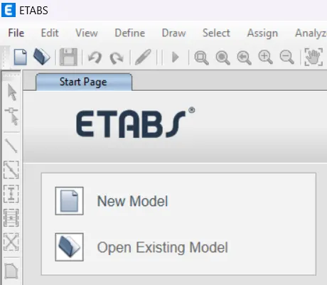
Initially,we open the software,where we go to New Model thereafter.
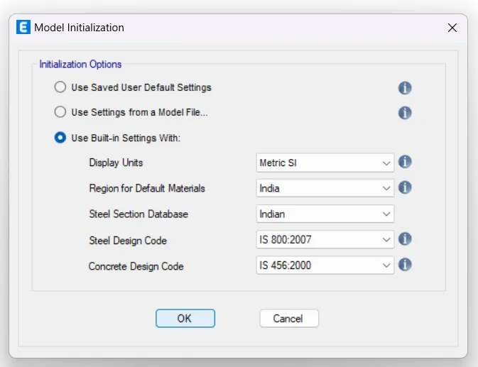
When then initialize the model using the Use Built-in Settings With: option and we even provide the relevant details.
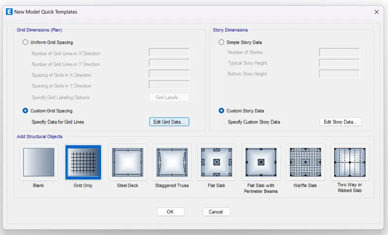
We then provide the required grid data as well the storey data using the options Custom Grid Spacing and Custom Story Data in New Model Quick Templates Tab.
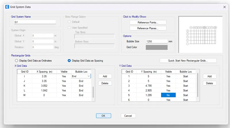
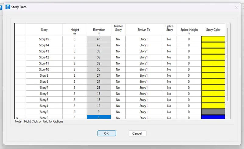
Where we form 15 storeys.
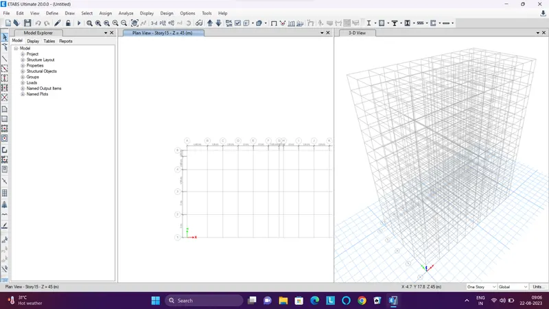
And we can find the grids basing upon the data provided.
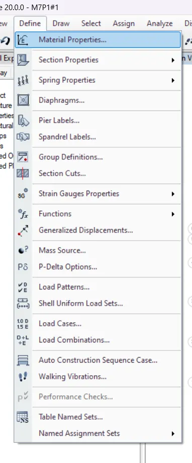
Then we form the required materials.We initially go to Define Tab>Material Properties...
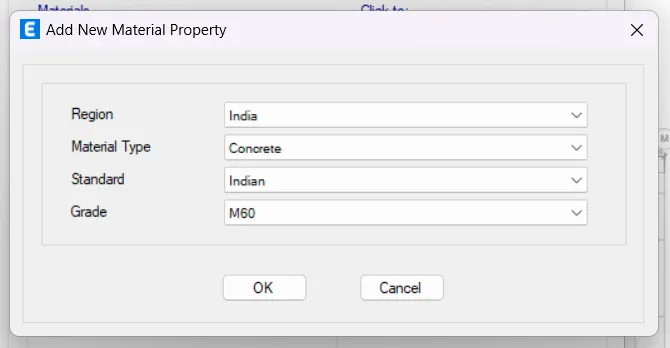
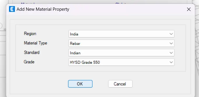
Using the option of Add New Material...,we add the required materials such as concrete and steel.
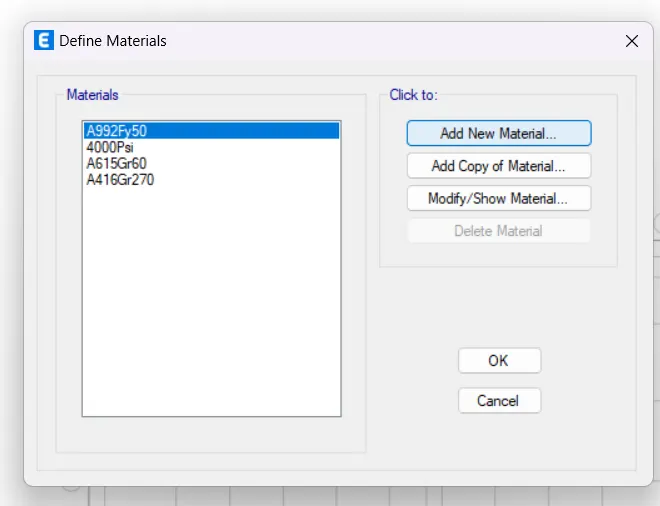
We use M60 Concrete and HYSD Grade 550 Steel for the construction.
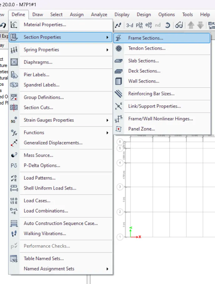
We then create the require sections.We go to Define Tab>Section Properties>Frame Sections... to define the column and beam sections.
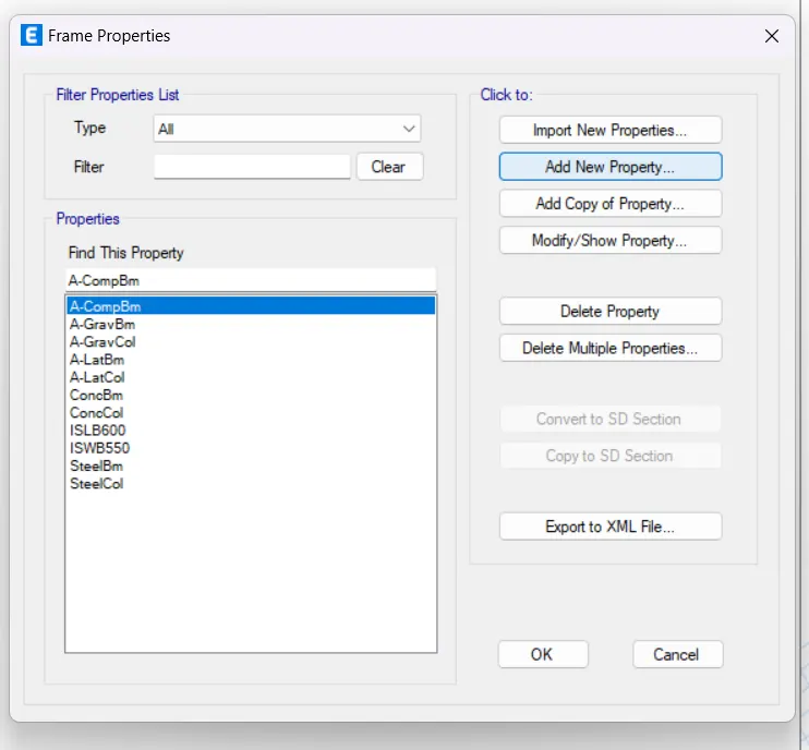
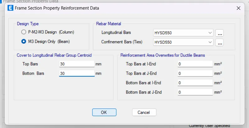
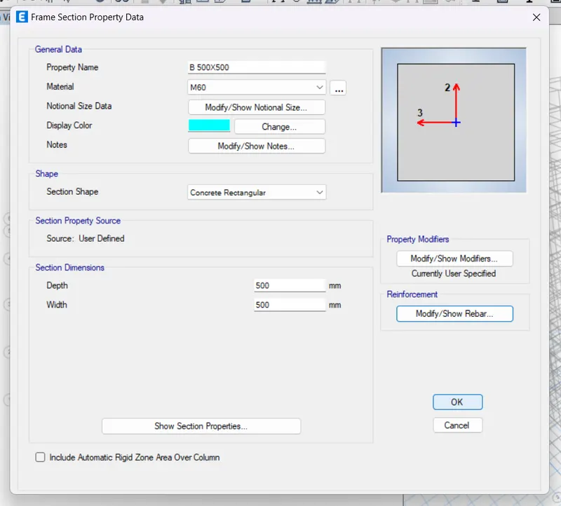
Using the option of Add New Property...,we create the require.
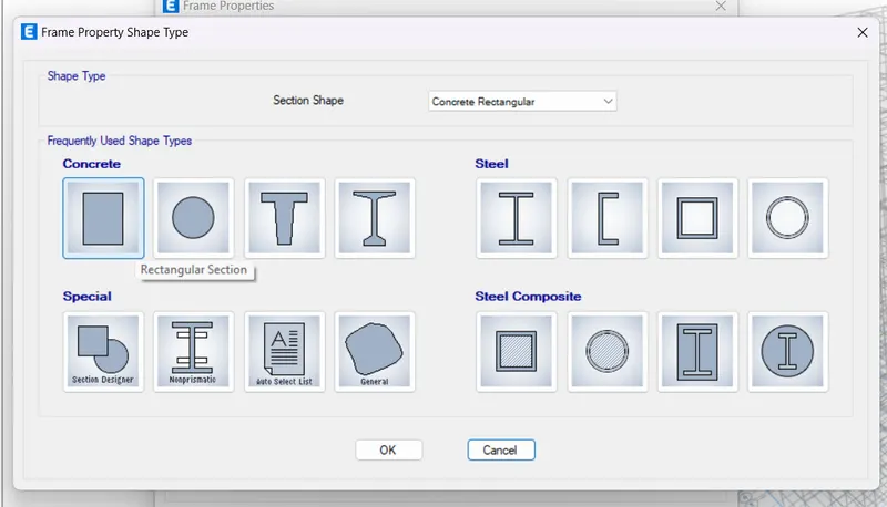
We use the Concrete Rectangular shape for the definitions of the sections.
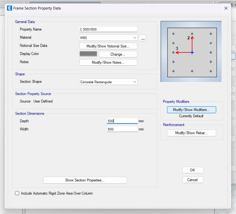
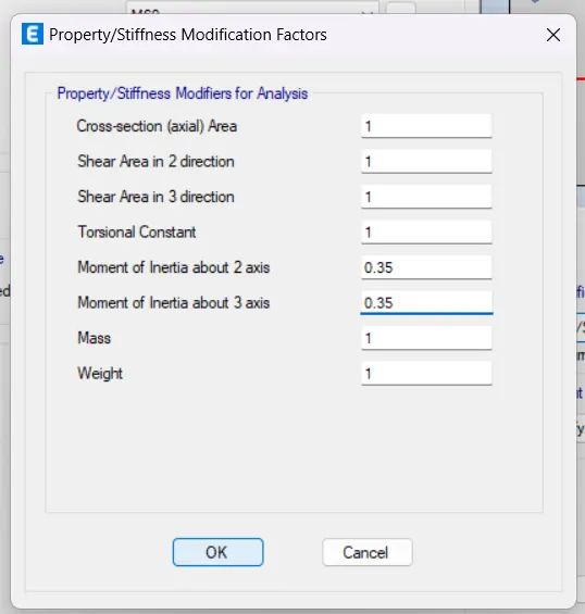
Where we create a column of size of 500 x 500 mm,where we provide the values for Moment of Inertia about 2 axis and Moment of Inertia about 3 axis as 0.7 in Property/Stiffness Modification Factors Tab for columns.
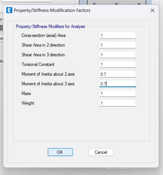
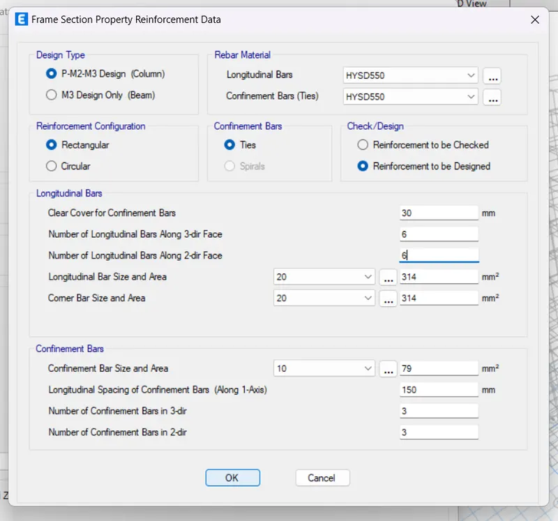
Similarily,we provide the same as 0.35 for beams.
Where we go to Define Tab>Section Properties>Slab Sections... to create a slab section.
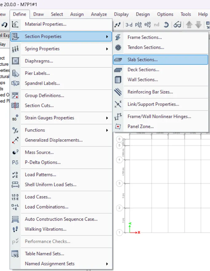
The we add a new section for a slab.
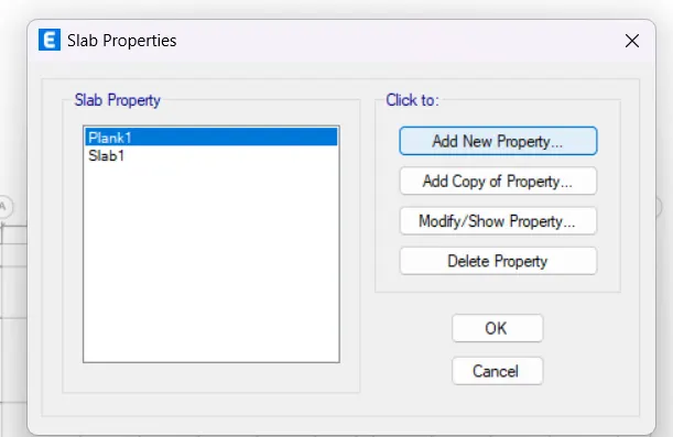
We provide the slab thickness as 150 mm where we assume it as Membrane,which means it doesn't take any load but transfers all the load to beams and columns.
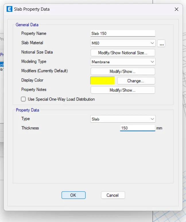
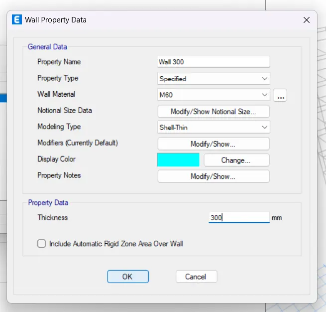
We then go to Define Tab>Section Properties>Wall Sections... to define the required shear walls.
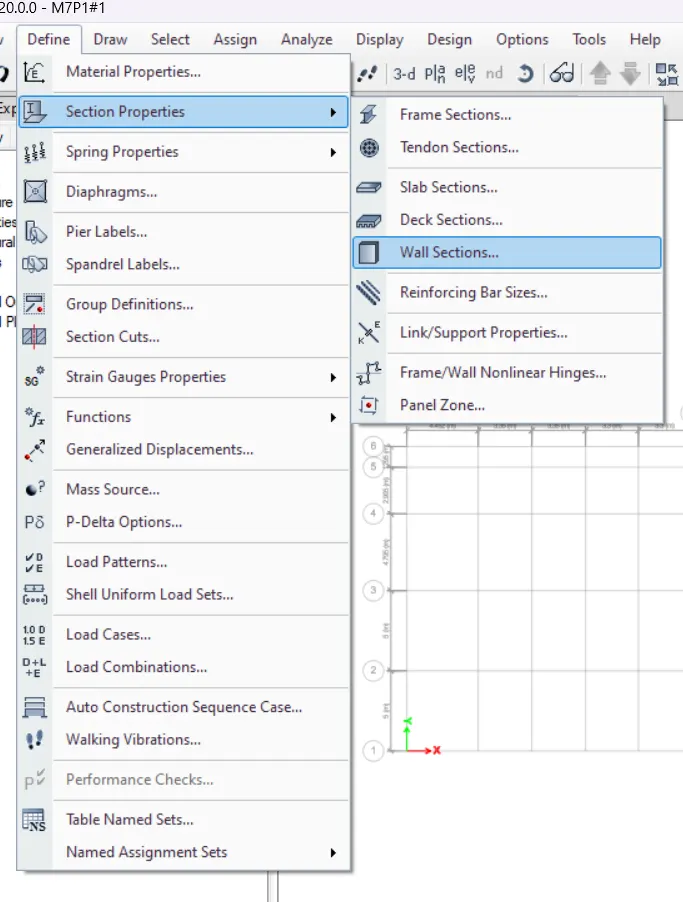
We then create a new wall section with a thickness of 300 mm.
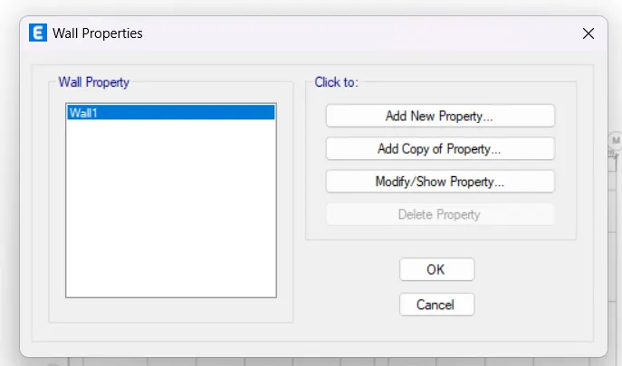
Where this shear wall is formed as Shell-Thin where it takes load.
After the formation of require materials and required sections,we model the structure.
We initially use the option of Quick Draw Columns where we place the columns all over and then we remove the unwanted columns.
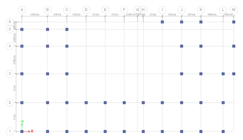
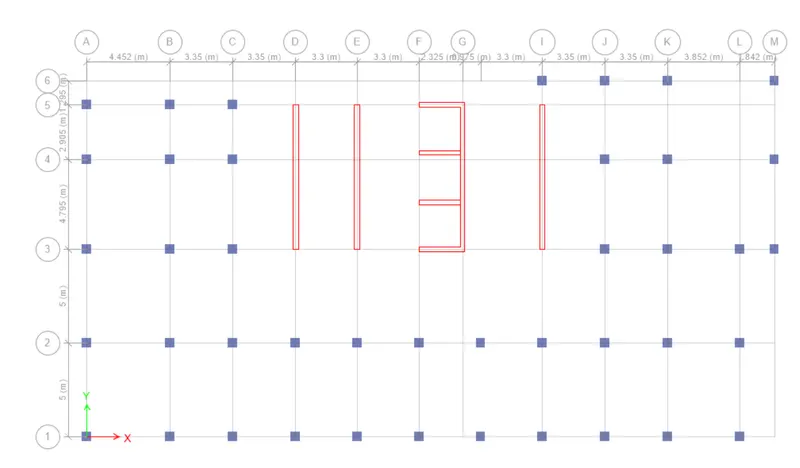
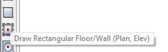
We then using the option of Draw Walls,we draw the required shear walls.
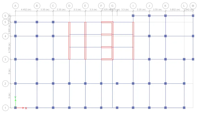
Similarily,we even draw the require beams.
In the similar manner,we even form the slabs.
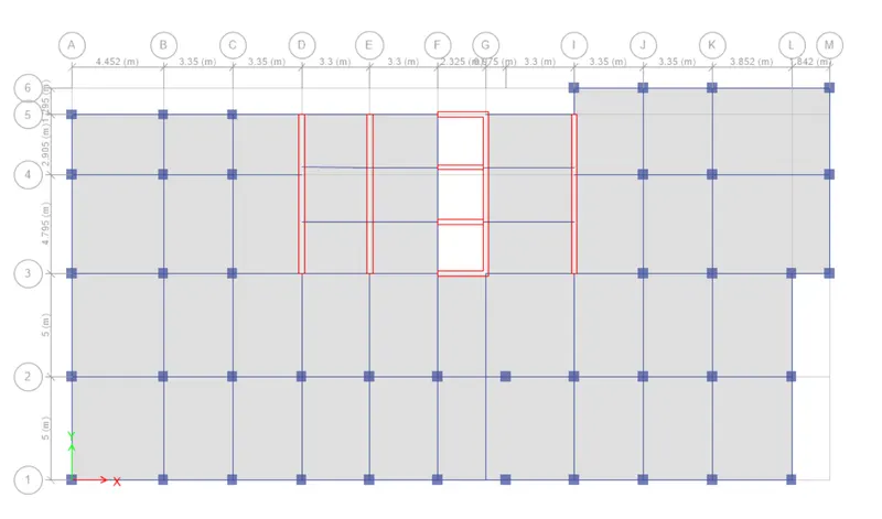
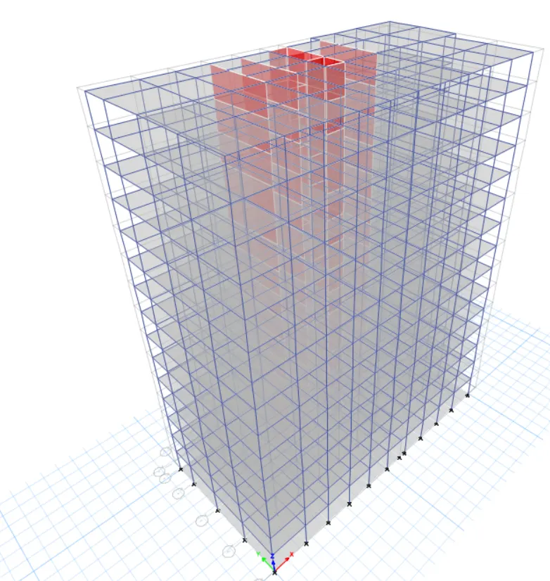
Thus,the model is formed and we can view in the 3D View.
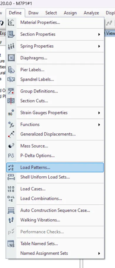
We then proceed with the load application.We go to Define Tab>Load Patterns...
Where as this is the basic step for the load application where before the application of the loads,we have to define the patterns for them.
Where we add the required load cases.
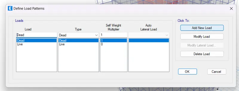
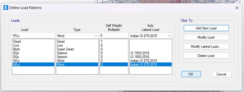
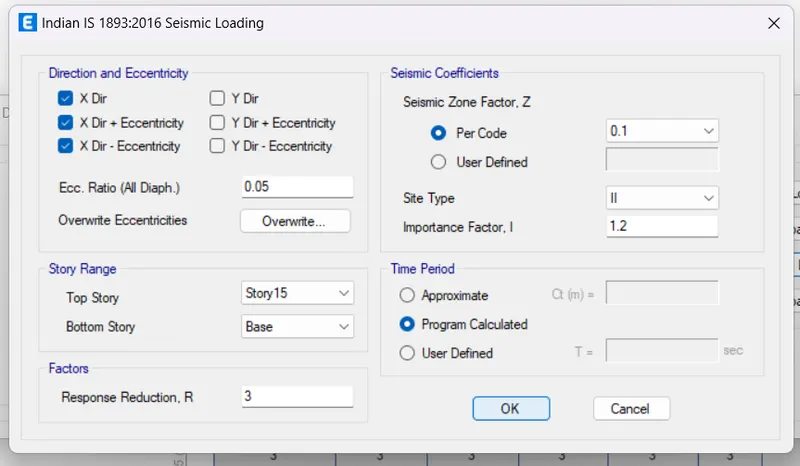
Where for the Earth Quake load,we modify the default as per the location.Where we assume the building is present in Visakhapatnam.Where we create 2 load cases where one for one direction and other for the other direction.
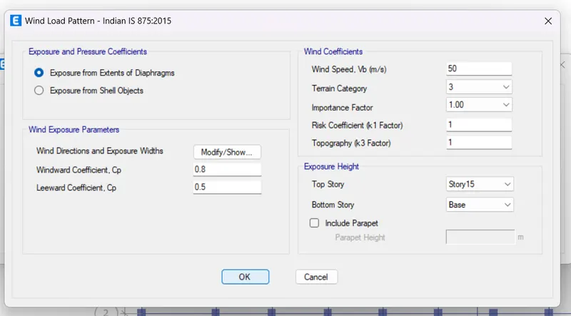
And in the same way,we provide 2 more cases for Wind Load where one will be for 0 degrees and other for 90 degrees.Where give the relevant details basing upon the location assumed.
In the resultant tab of Wind Load Pattern-Indian IS 875:2015>Wind Exposure Parameters>Wind Directions and Exposure Widths>Modify/Show... we give only one angle where one is one case while the other for the other.
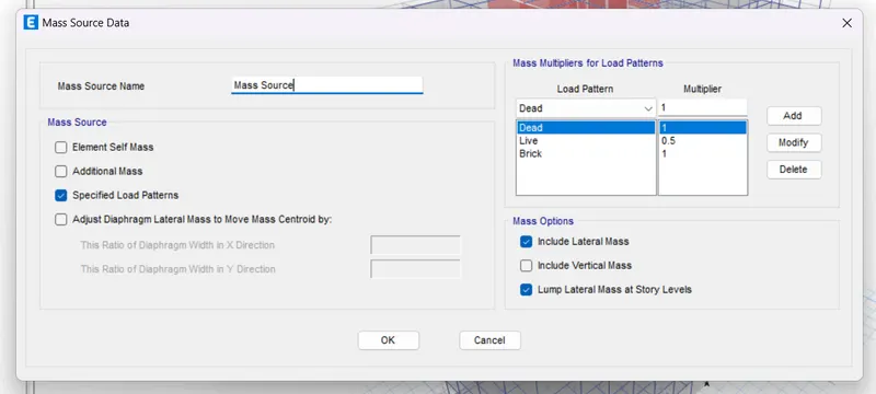
And,under the analysis of the eartquake design,we have to define the mass source where this will be the weight getting impacted during earthquake.
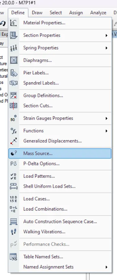
Where we go to Define Tab>Mass Source...
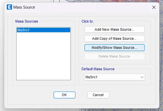
Where we add the require loads in the mass source.
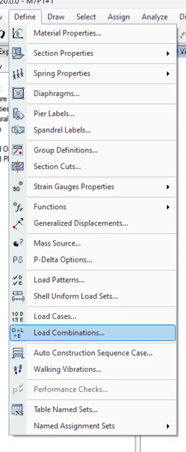
We then define the load combinations on to the structure as no load will act singly on a structure.
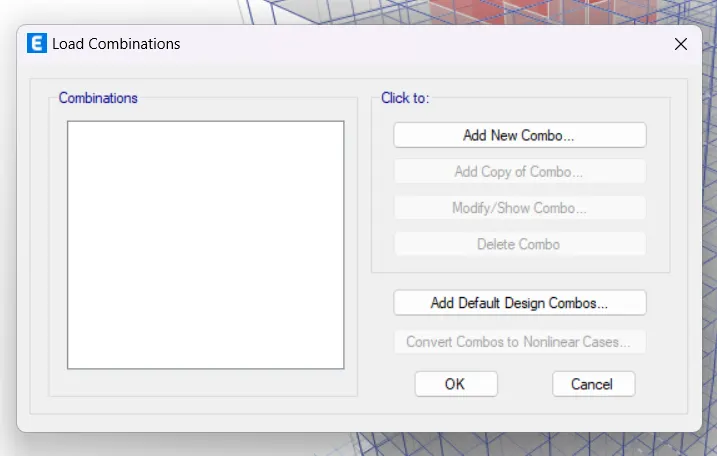
We go to Define Tab>Load Combinations...
Where using the option of Add Default Design Combos...,we add the load combinations by software.
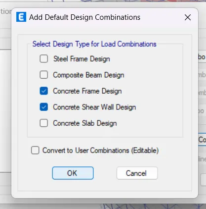
Where in the resultant tab of Add Default Design Combinations,we select Concrete Frame Design and Concrete Shear Wall Design.
With this,we have created all the required loads,where now we proceed with the load application.
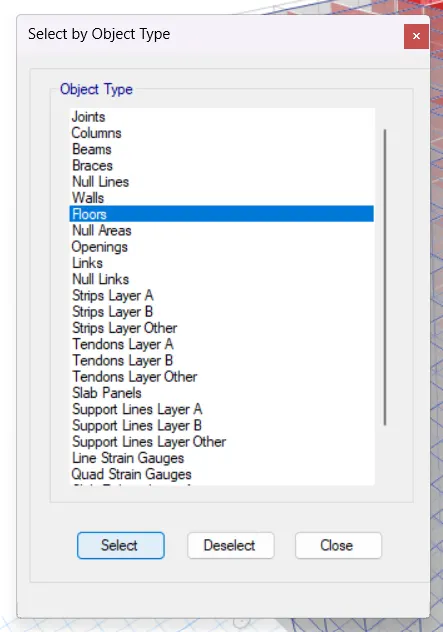
Now,we go to Select Tab>Select>Object Type...>Floors>Select.

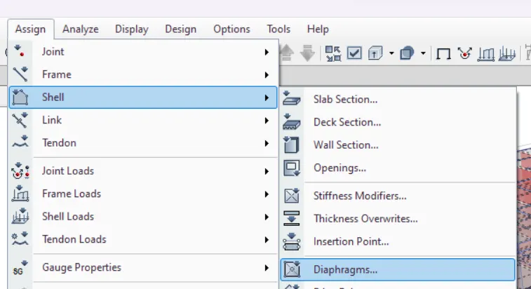
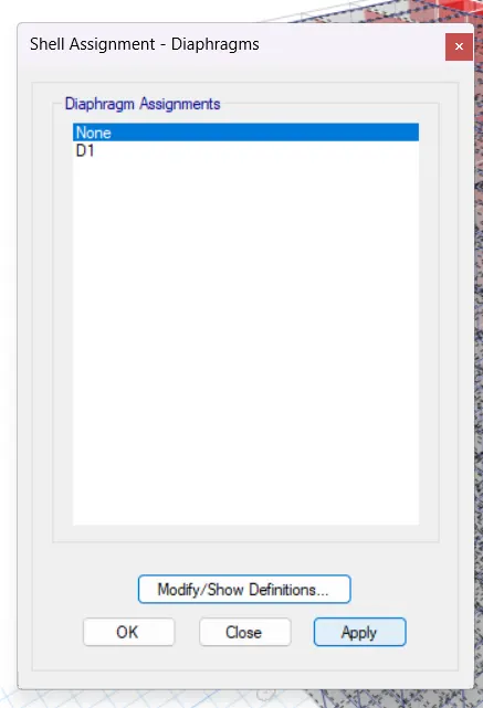
Now,we go to Assign Tab>Shell>Diaphragms...
To make the available slabs to act as floor diaphragms.
And then apply the available.
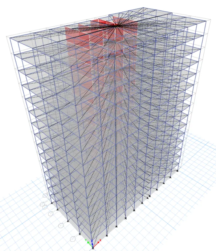
In the similar manner,we select the required objects and apply the loads.
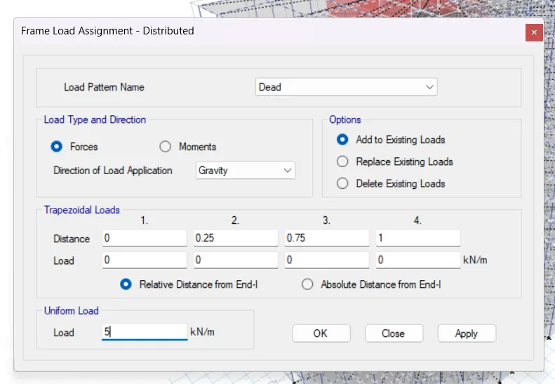
So,the applied loads be,
Wall Weight-5 KN/m
which is to be applied all over the beams.
Dead Load-3 KN/sq.m
Live Load-3 KN/sq.m
which are to be applied all over the slabs.
Now,we check the Bending Moment Diagrams and Shear Force Diagrams of the structure along with the Axial Force Diagrams.
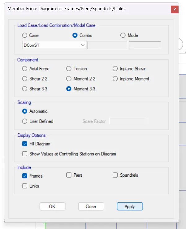
We we use the option of Display Frame/Pier/Spandrel/Link Forces...
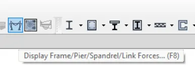
Where we then select the required to be displayed.
The below be the Bending Moment Diagram and Shear Force Diagram for one of the floor respectively.
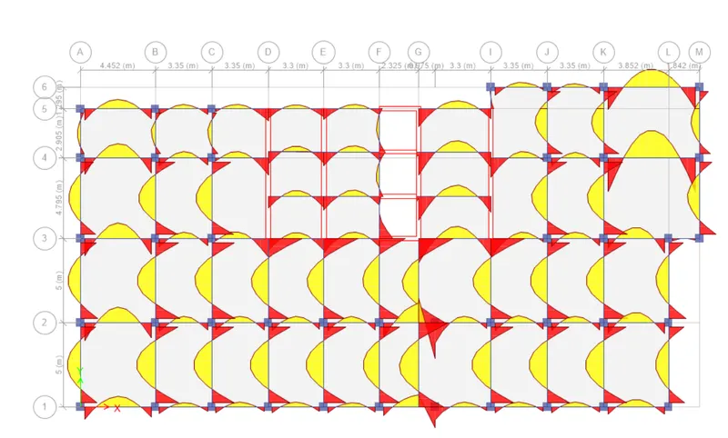
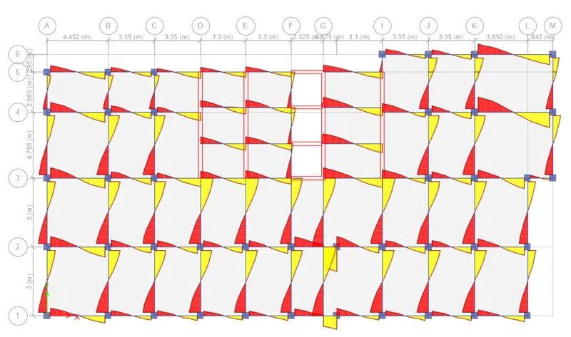
From the above images,we can find that the diagrams are common and in a similar manner for the all the beams.
So,we can expect that the behaviour of the building in load resistance is common and safe.
The below are the Bending Moment Diagrams and Shear Force Diagrams of a one vertical set of frame respectively.
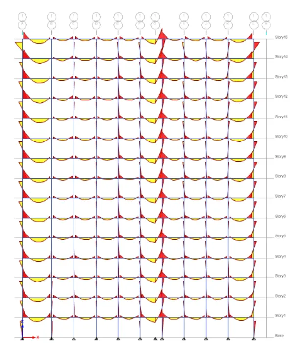
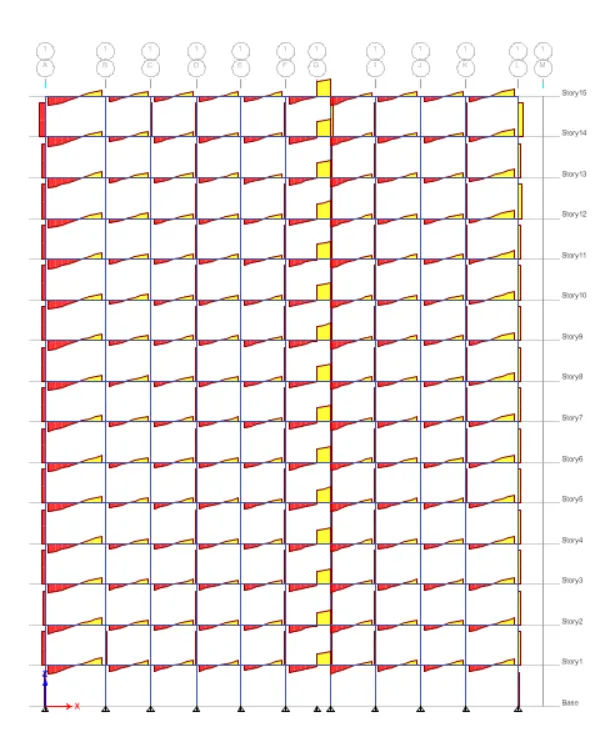
Here,also the diagrams look common.So,it's safe and normal.
The below be the Axial Force Diagram for a vertical set.
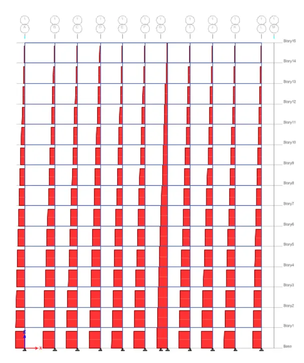
And it too looks common,and we can see that the load path for the gravity loads will be like the above.And the load path is safe.
Now,we check the base shear obtained for this building.
We go to Display Tab>Show Tables...
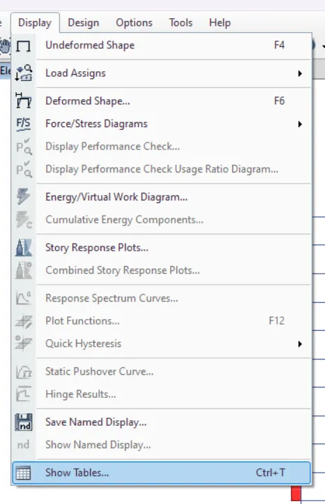
Where we then select the Base Reactions.
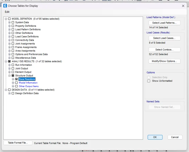
And we can find the resultant base reactions.
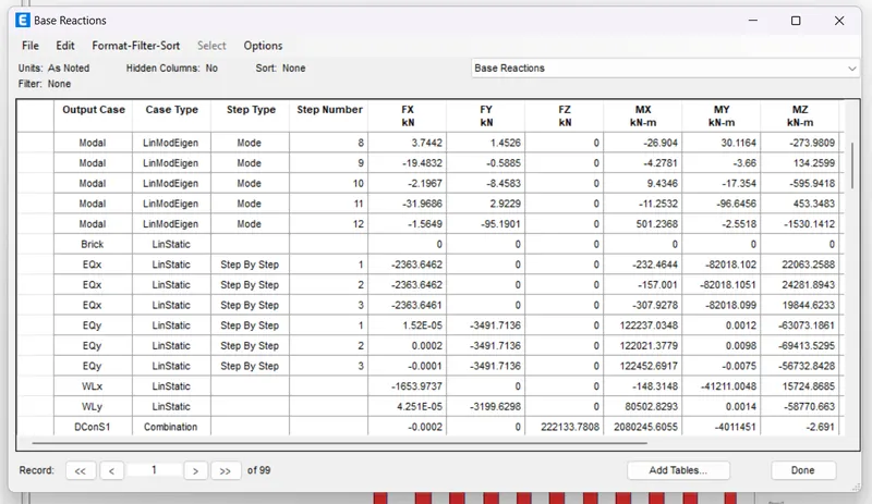
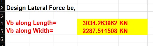
And we had even calculated the base reactions manually,where they both are near by and we confirm the calculations done by the software are good.
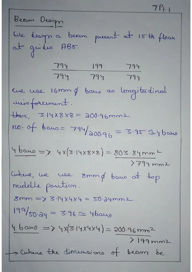
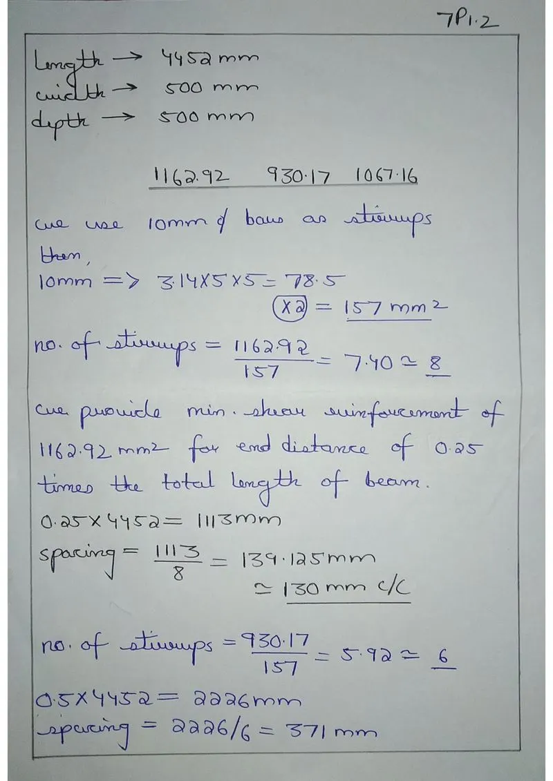
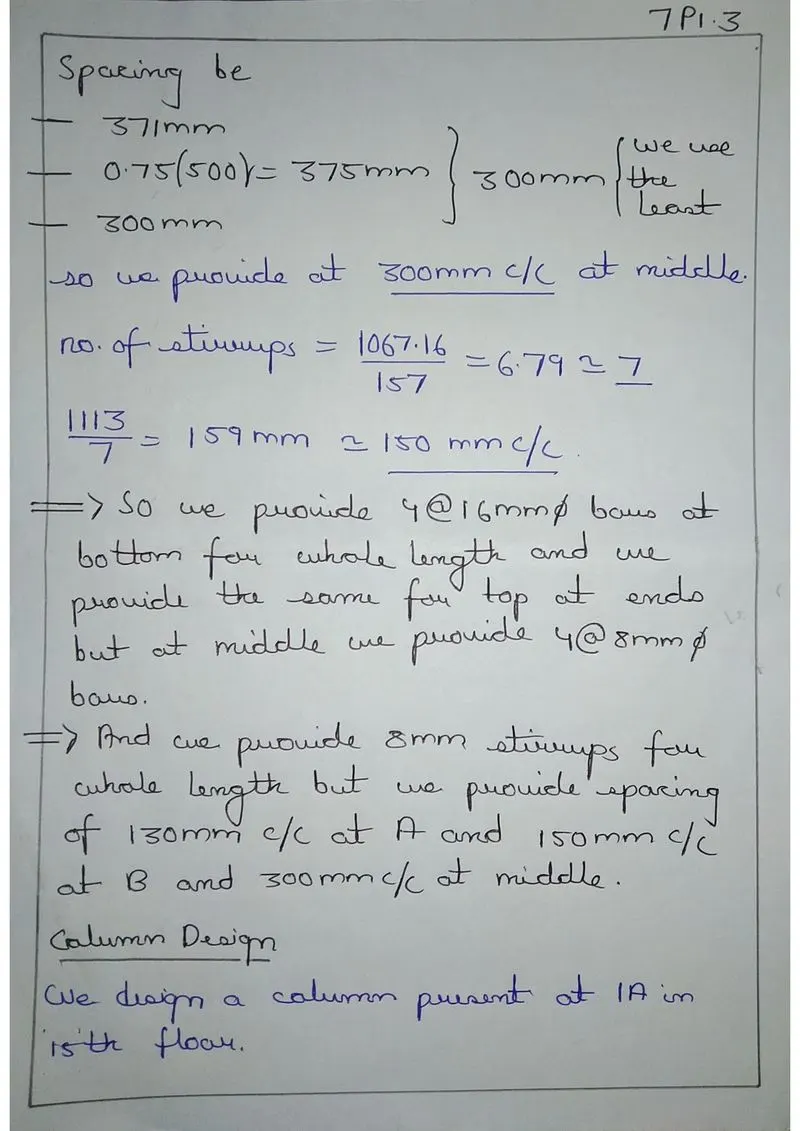
The longitudinal reinforcement and transverse reinforcement of the beam respectively be,
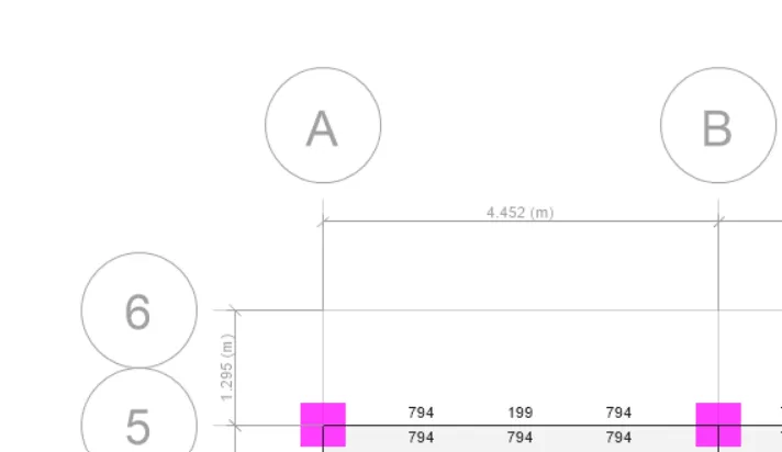
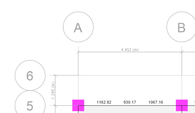
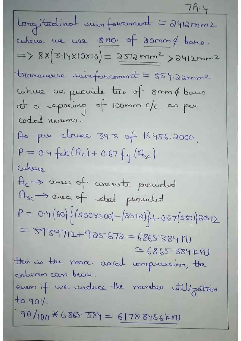
The longitudinal reinforcement and transverse reinforcement of the column respectively be,
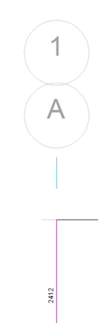

The axial load acting on the column be,
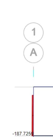
Therefore,we design the beam and column.