Project 1 - MODELLING, ANALYSIS & DESIGN OF TALL BUILDINGS IN ETABS
AIM:-
I will accomplish a project on modelling, analysis & design of a state-of-the-art tall building using ETABS software.
INTRODUCTION:-
In this project I will import the architectural drawing in ETABS then model a 25 storey building, and after that I will assign all type of loads and load combination. Then, I will run the analysis and design that building as per Indian standard and finally represent the following details-
- Manual calculations for the base reactions in gravity load cases (in excel / word document)
- Submit ETABS model with the complete model of the tall building (exported .e2k format, do not attach .EDB format directly)
- The model should pass all design and serviceability requirements.
- A comprehensive project report from the ETABS software (as PDF file)
Procedure:-
a. Modelling:-
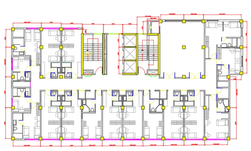
- To comprehend the architectural plan provided by the architect and look-out for the key information from the drawings.
- Here I have provide dimention from one column center to another to draw the same grid in ETAB.
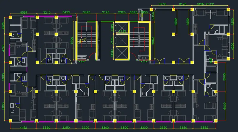
- Import the architectural floor plan (provided by the architect) in ETABS model to start with the modelling. (Here I put grid dimensions manually instead of importing autocad drawing)
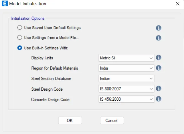
First open ETAB and sent initial parameters
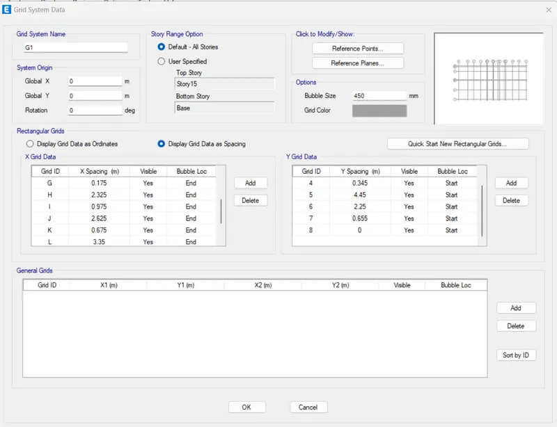
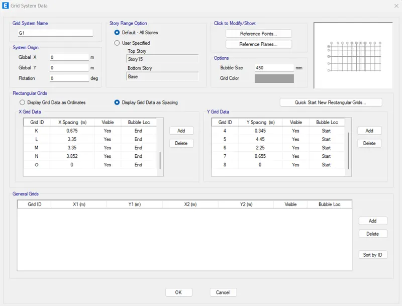
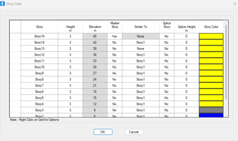
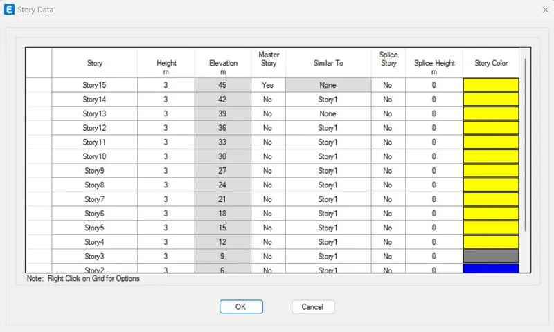
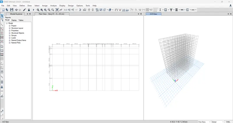
- Create grid lines, story levels & story heights to set-up a project.
Now set grid data
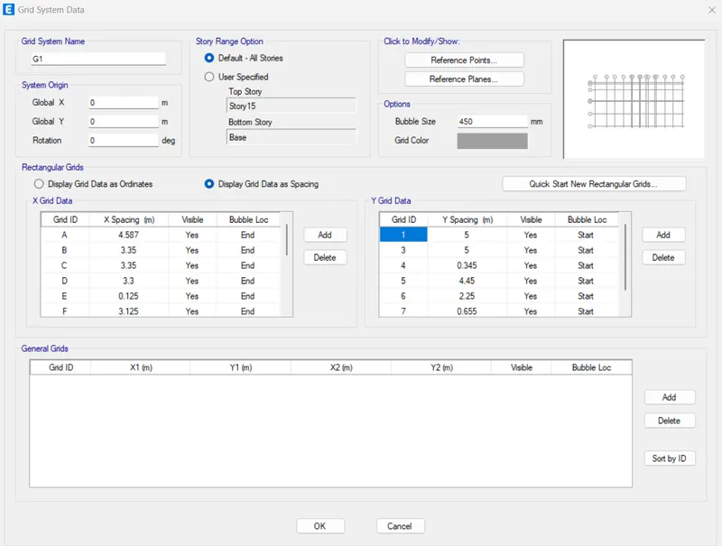
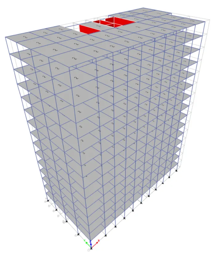
Now create 15 storey building
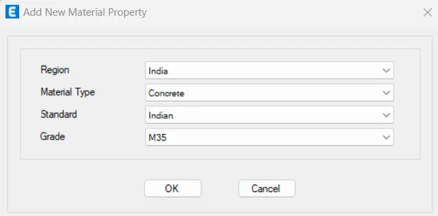
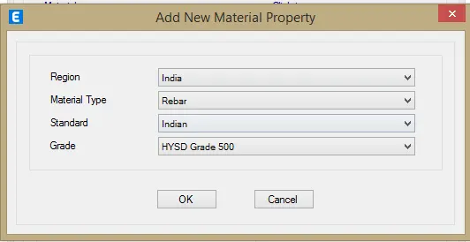
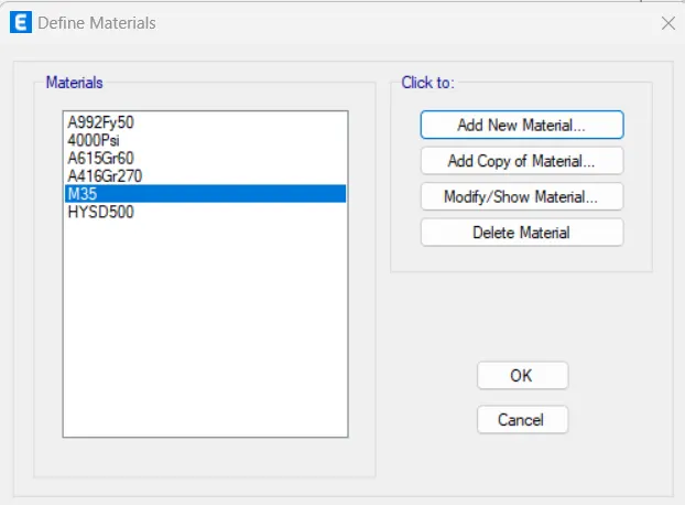
- Create material definitions for the concrete, rebar & structural steel.
- Create slab, beam, column & wall properties to be used further in the project.
- Then, define the section property for column, beam and wall. For this, go to define tab --> section property --> frame section --> Beam 400X500mm and column 550X550mm and for central columns as 800mm X 800mm.
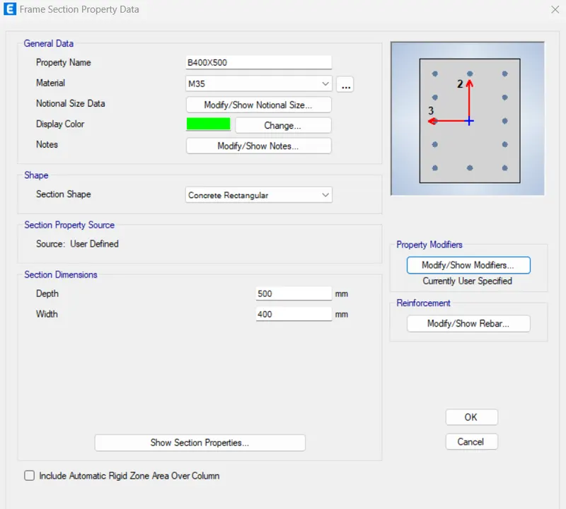
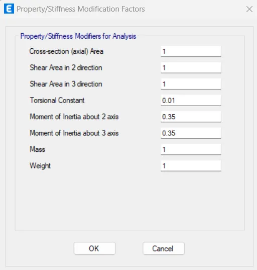
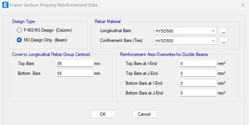
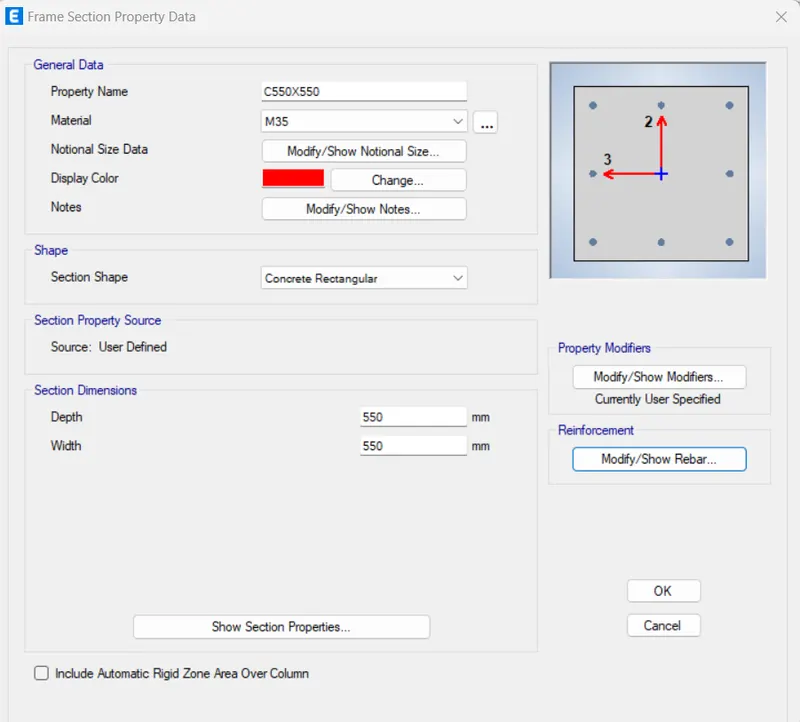
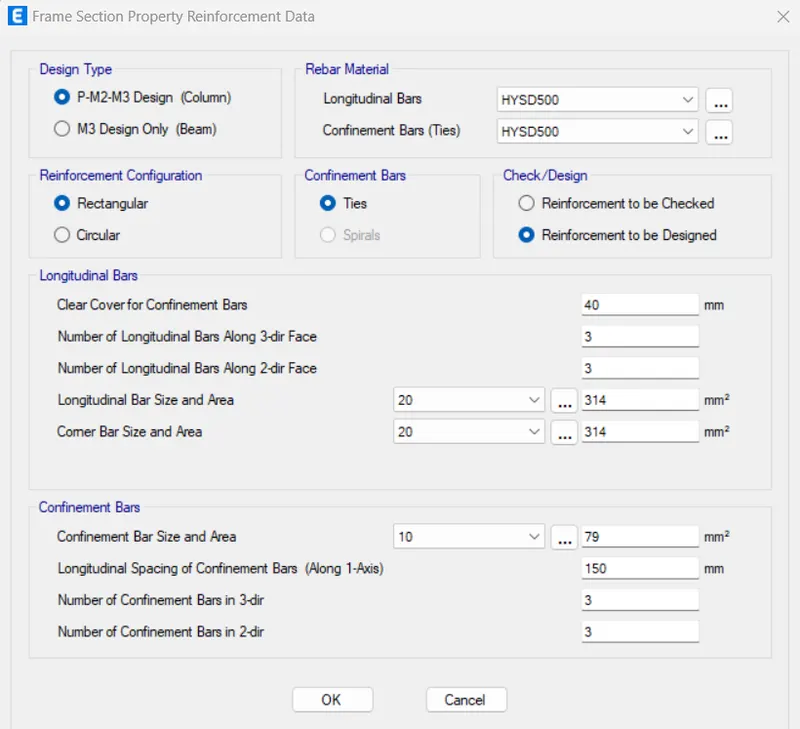
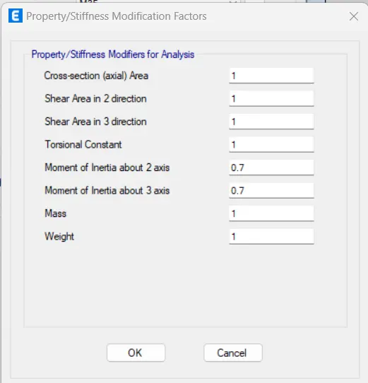
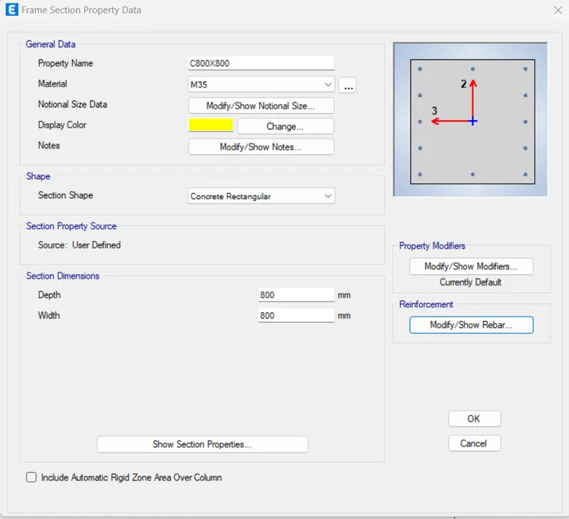
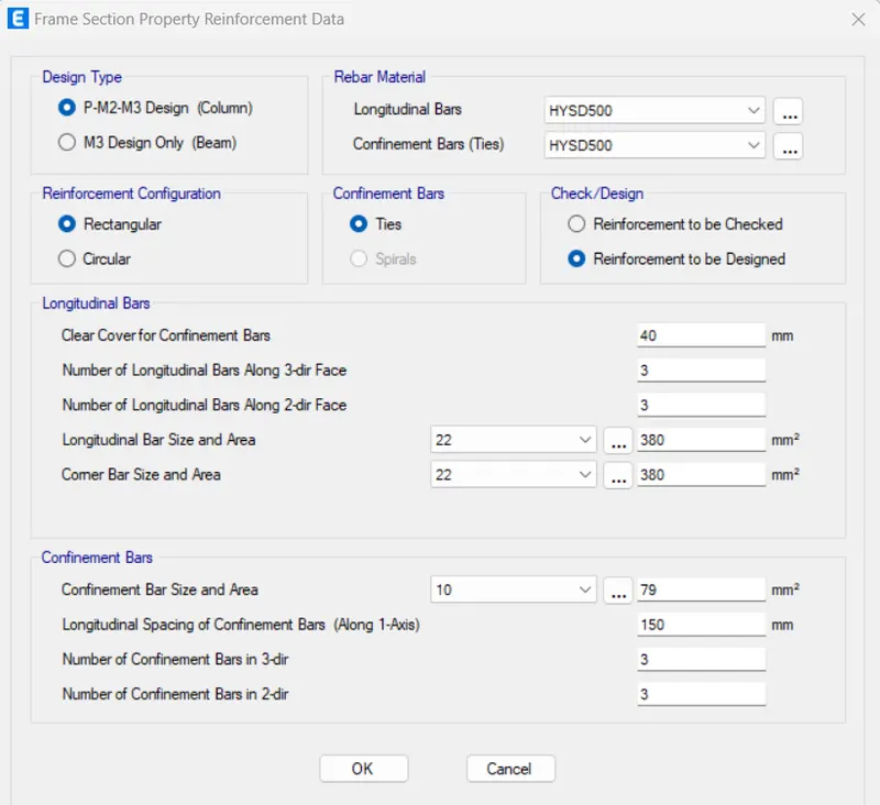
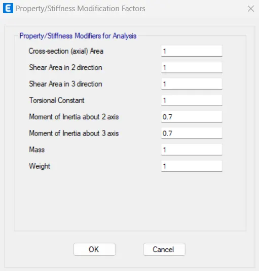
- Now, define the slab properties. Define --> section properties --> slab sections --> Slab150 and slab 125.
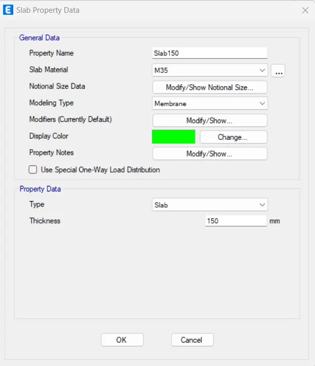
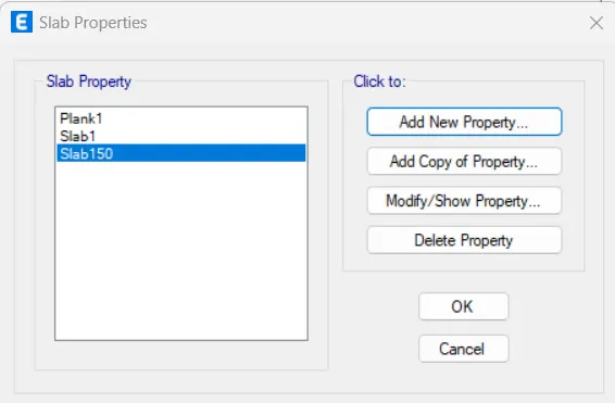
- Next thing that we need to define is the wall properties. Define --> section properties --> wall sections --> wall250.
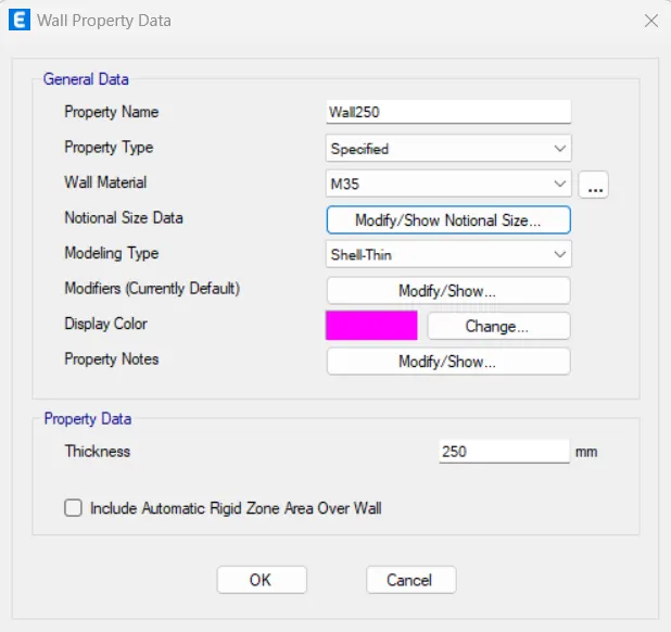
- Next thing that we need to define is the wall properties. Define --> section properties --> wall sections --> wall150.
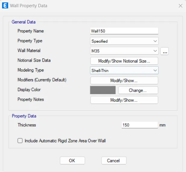
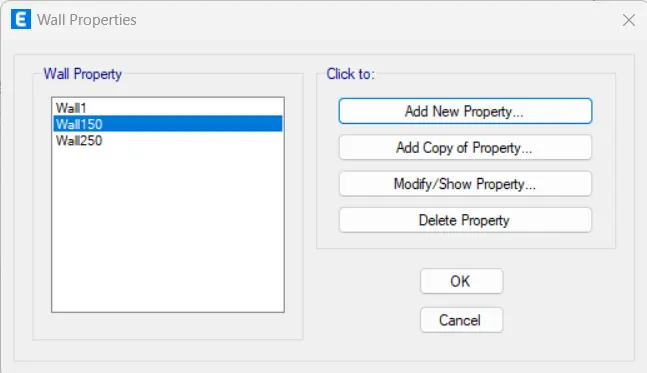
- Hence we have now defined the material as well as section properties, so now we need to place the components in the suitable positions.
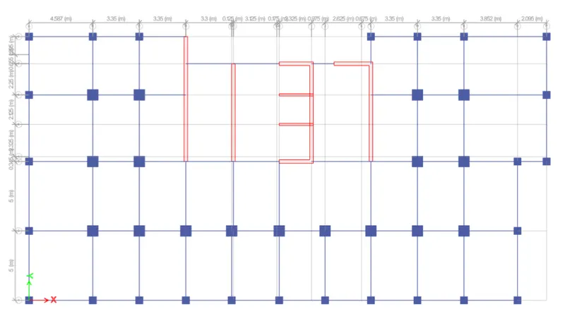
- Model typical floor plate using shell & frame elements as indicated in architectural plan.
- After this we need to place the slabs, for slab we use slab150
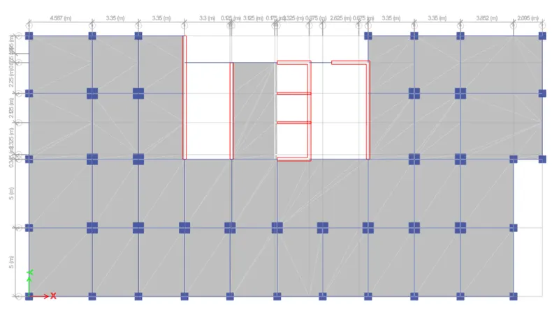
b. Loadings & Load combinations
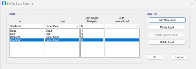
- Define load patterns for gravity cases
Define --> load cases --> Provide Brickwall & Floorfinish
 .
.
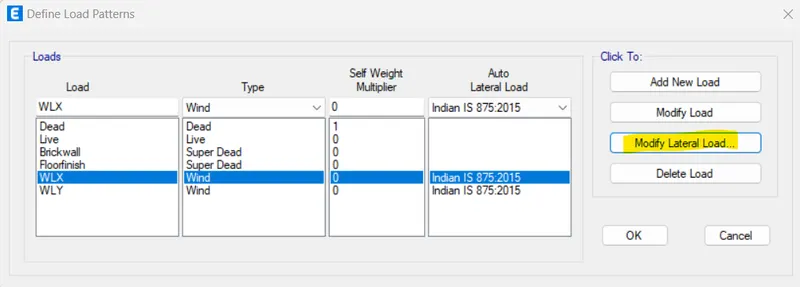
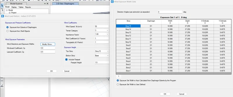
- Define load patterns for the lateral load cases using the wind & seismic parameters provided.
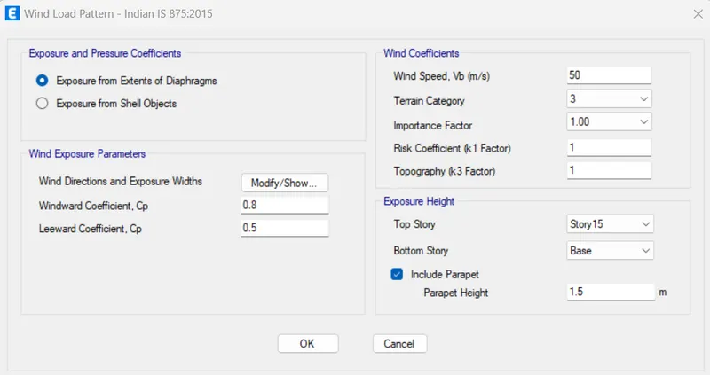
For wind load I have considered building location as Chennai.
Basic wind speed 50m/s
Terrain category 3
K1=1; K2= 1.105; K3=1; K4=1
Go to Define --> load cases --> Provide WLX and WLY as per IS875-2015
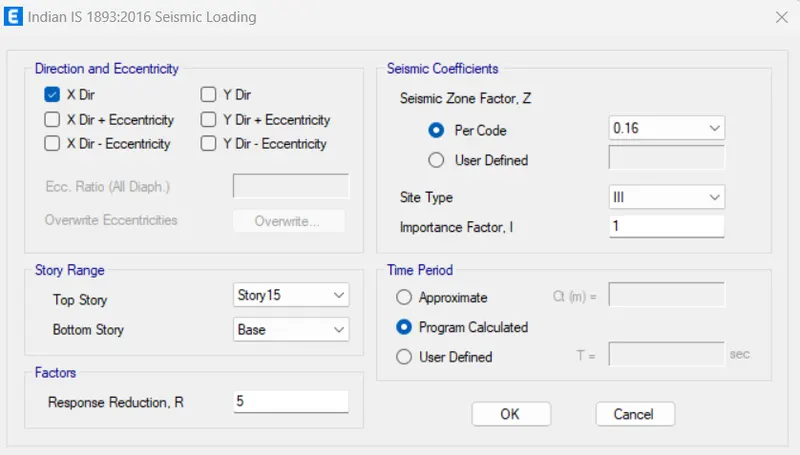
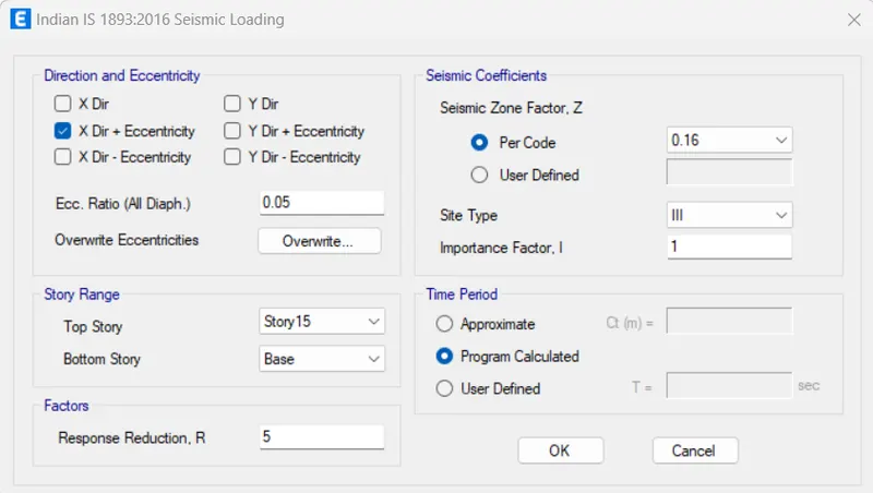
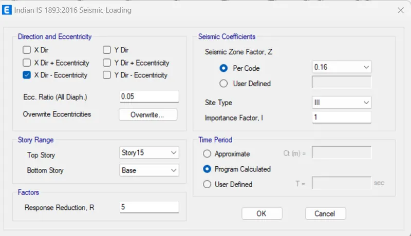
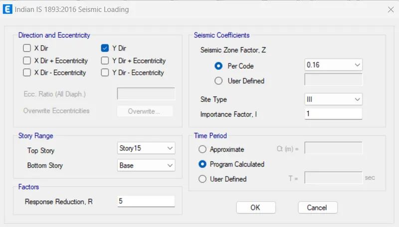
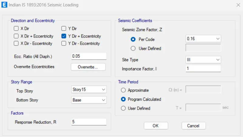
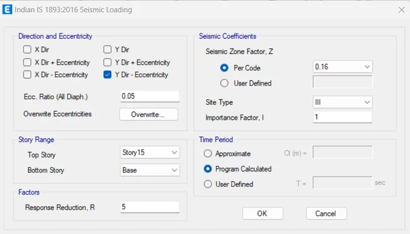
Now define seismic load cases Define --> load cases --> Provide DL, LL, Eqx, Eqx+, Eqx-, Eqy, Eqy+, Eqy-.
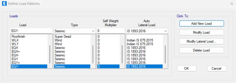
As per IS-1893 Chennai is in seismic zone-III (zone factor is 0.16)
Now, we need to assign these loads:-
-
- For live load take the value as 2kN/m2">m2 with reference to IS875:part 2.
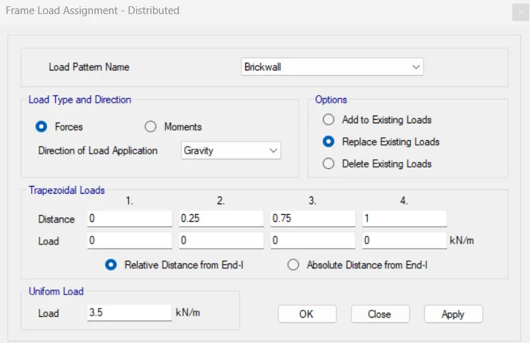
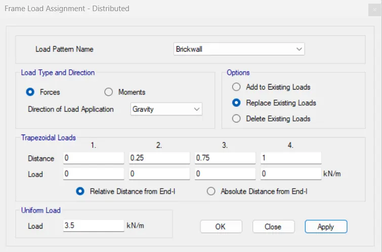
- Take Brickwall load as 3.5kN/m
- Floor finishes as 1.5kN/m2">m2
- Parapet wall load as 1 KN/M
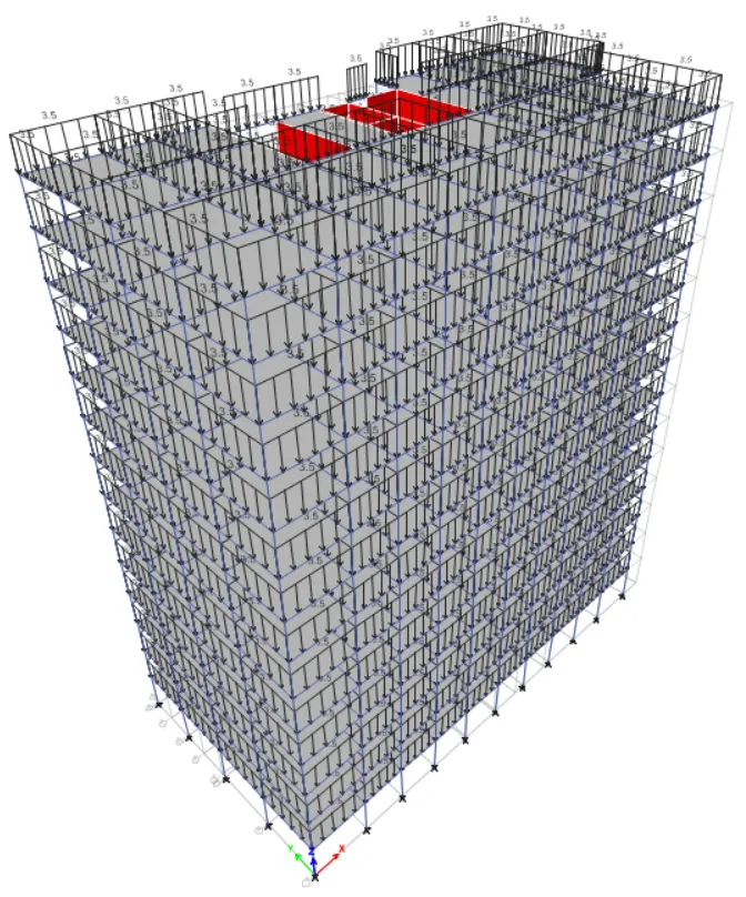
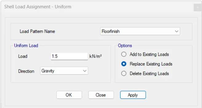
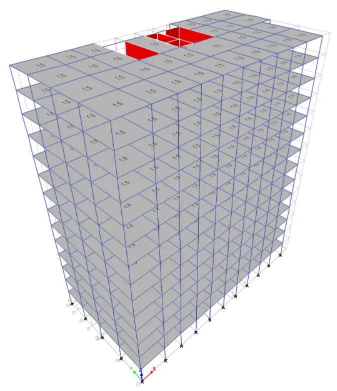
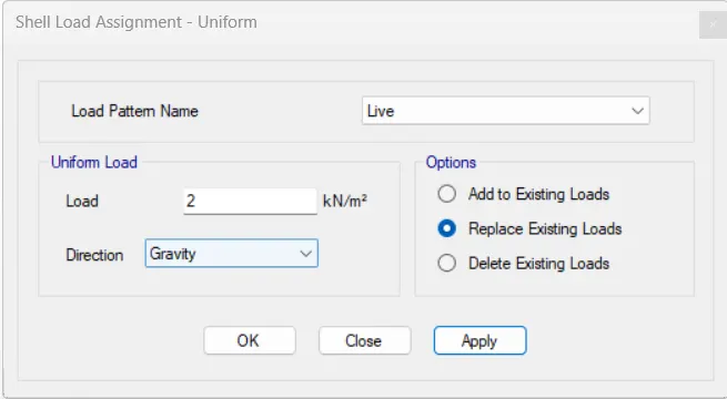
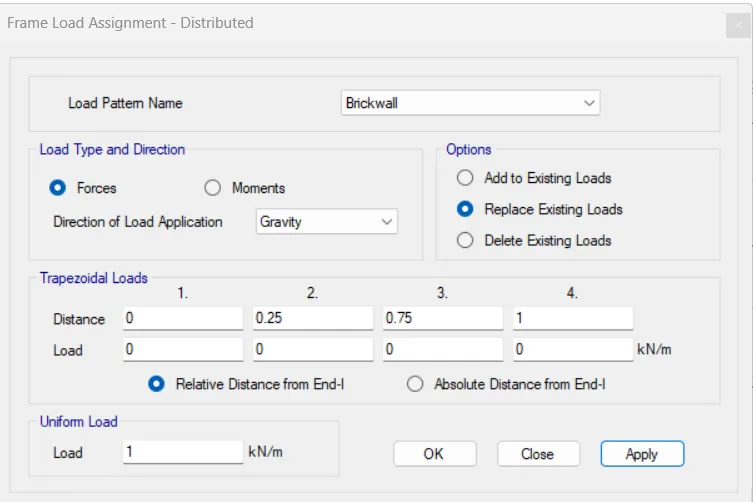
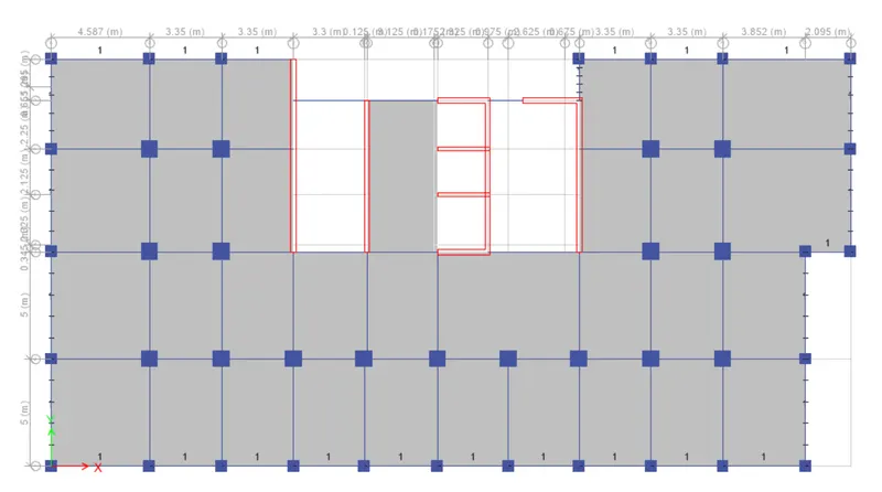
- Define mass source for the earthquake loads
Define > Mass Source
As per the IS 1893 guideline, the reduced live load and all dead loads are considered for mass source. This proportion of building weight is mandatory to calculate seismic forces.
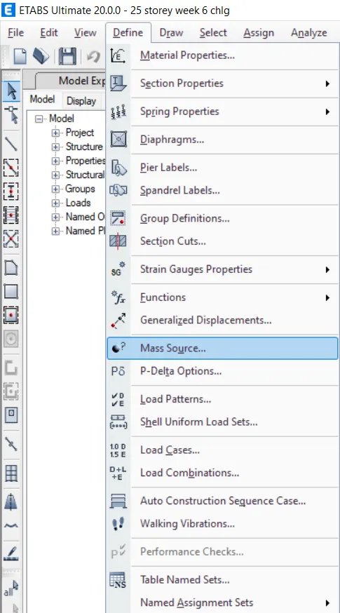
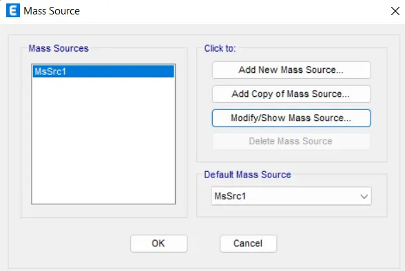
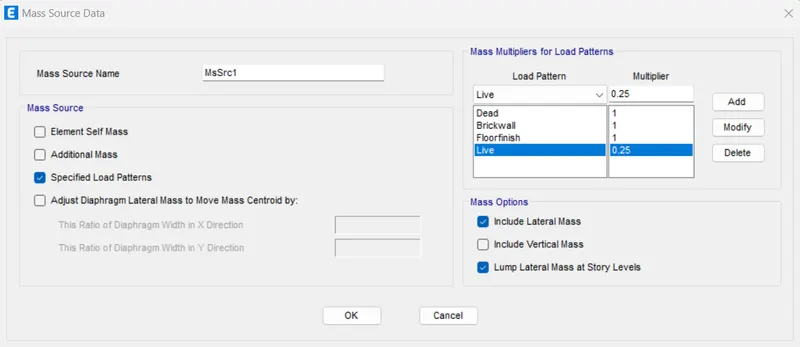
- After defining mass source, next we have to define the modal case. Keep the max no. of modes as 20.
- Next we need to define the response spectrum function. Define--> Response spectrum --> Func. name: RS function -->ok
- Then go to load case --> add new case --> RSx (U1)--> load case type - Response spectrum-->Then fill load applied details.similarly add another load case as RSy (U2).
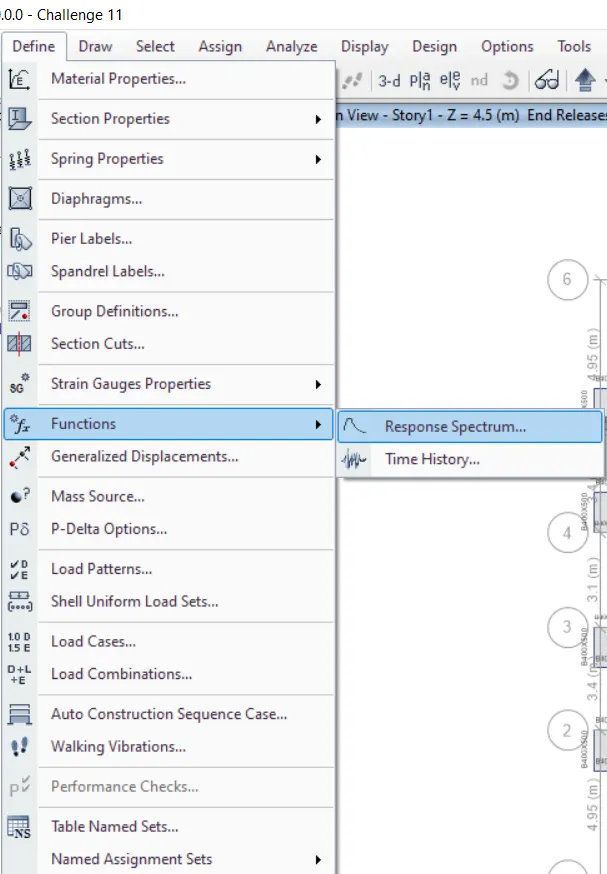
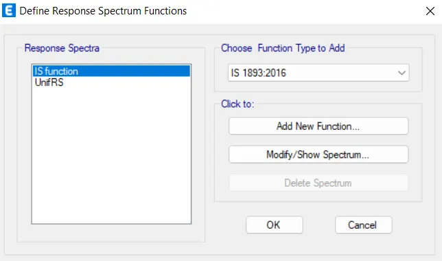
- Click to add new function.
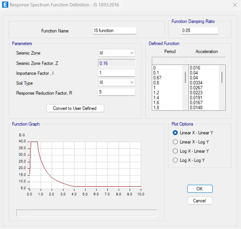
Now add Resonse spectrum in load cases as RSX and RSY
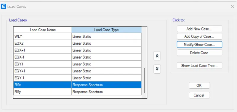
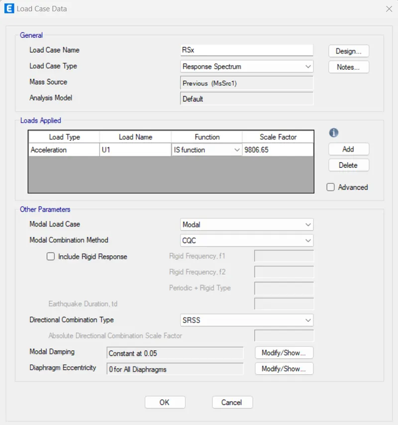
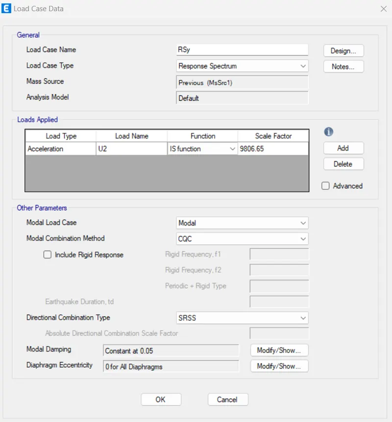
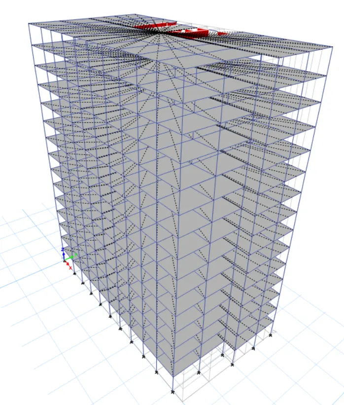
- Now, Assign --> shell --> diaphragms --> D1 --> Apply.
**Here You need to define wind load pattern WLX and WLY to see the effective wind table**
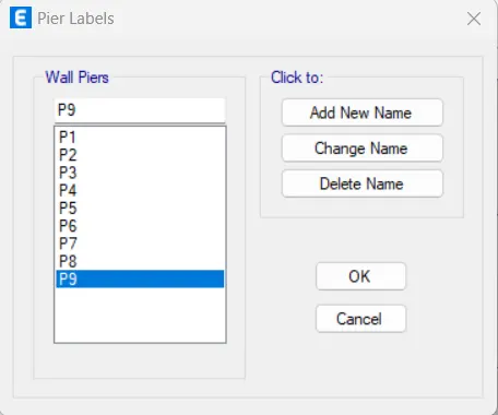
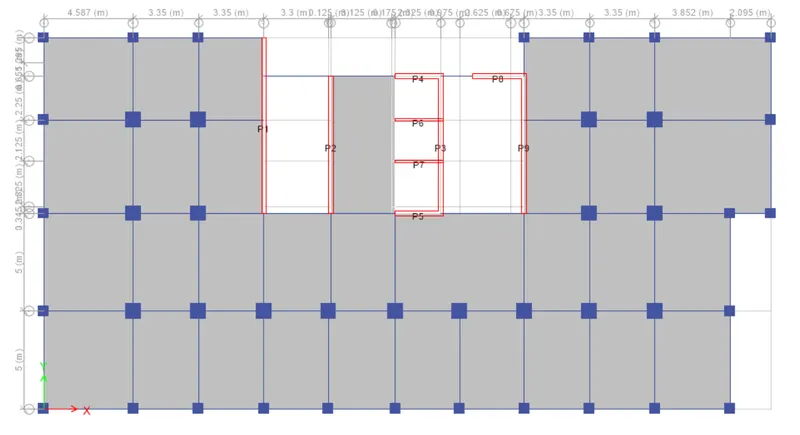
- Then assign pier labels.
- Assign support condition as fixed support
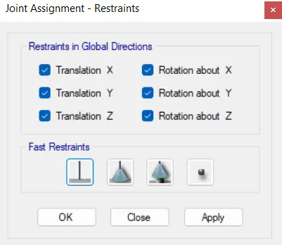
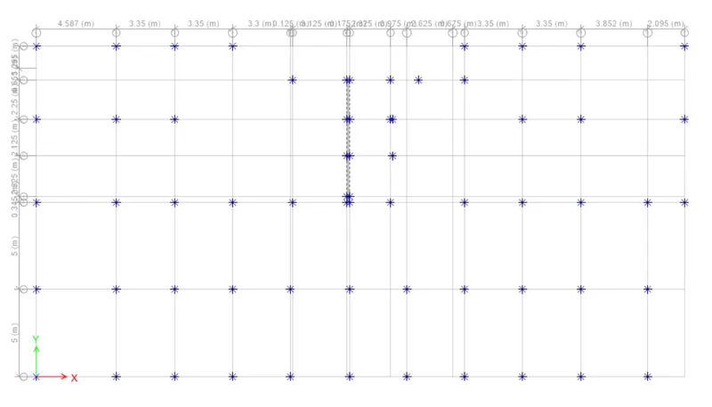
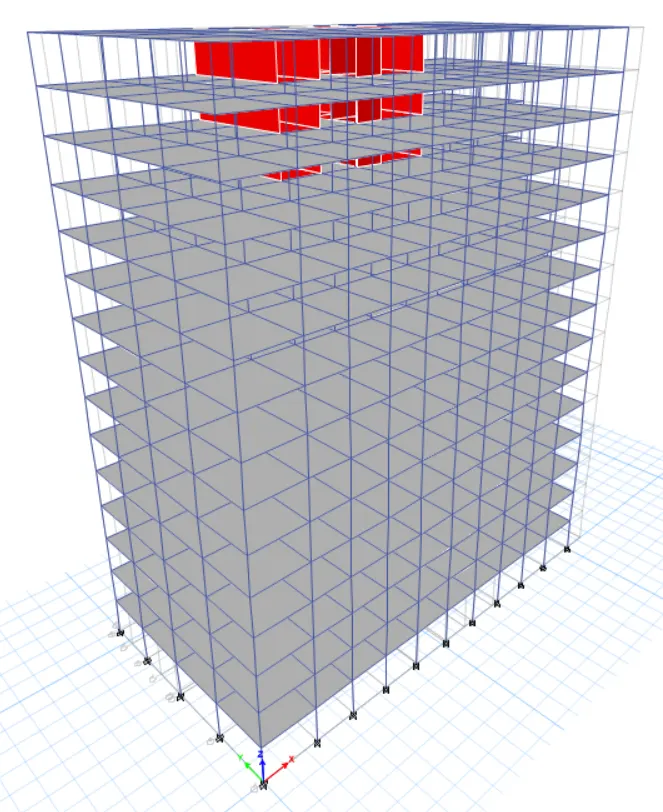
- Create service & ultimate load combinations as per IS 456:2000
-
Define > Load combinations
As per the Indian standards IS 456 and IS 1893, the default combinations are generated using the ETABS predefined set.
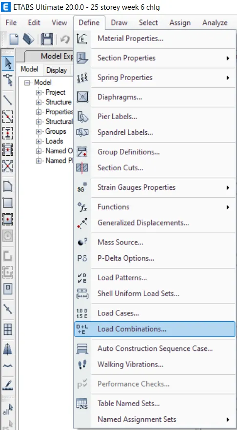
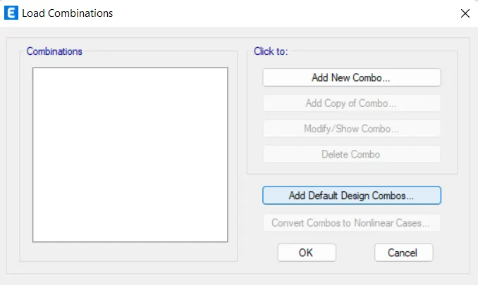
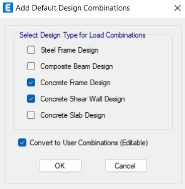
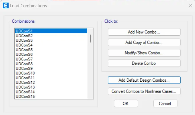
- All the inputs have been provided, now we can check the model. Analyze --> check modal.

c. Structural Analysis
- Now, we can run the analysis.
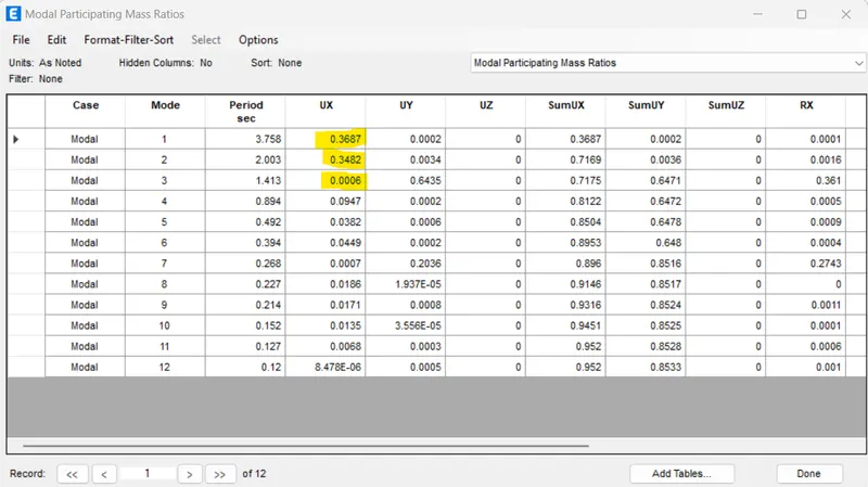
- Once, the analysis is over, go to display --> show tables -->analysis result --> structure output --> modal information --> modal mass participating ratio.
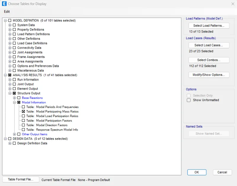
- Mode 1 - 36.87% ; Mode 2 - 34.82% ; Mode 3- 0.06%
- Hence, the mass participation of translational mode (first two fundamental modes) is greater than torsional mode(third mode).
- Obtain the shear force & moment diagram for the floor beams & columns.
- Check the gravity load path in the structure if it follows the designer’s intent.
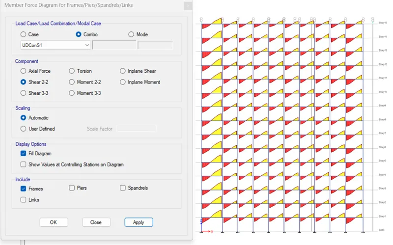
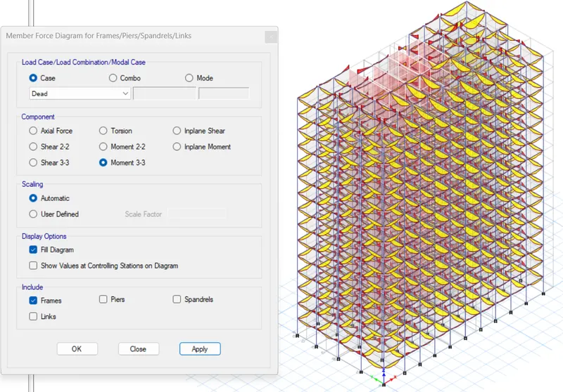
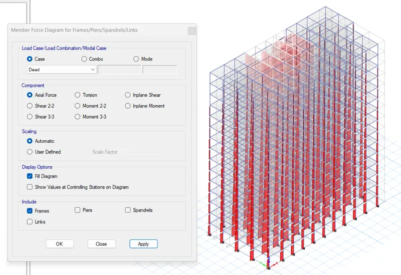
As per the above mentoned results we can be certain that loads are following a proper channel (from slab to beam and beam to column and column to foundation.
- Perform quick hand calculations to confirm the base reactions for the gravity load cases.
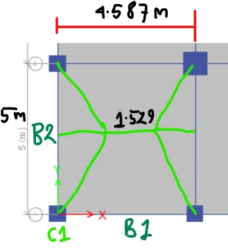
Slab thickness = 150mm
Beam size= 300mm X 300mm
Live load = 2 KN/m2
Floor finish= 1.5 KN.m2
Brickwall load= 3.5 KN/m
Self weight of slab = 0.150 X 25 KN/m2 = 3.75 KN/m2
Total load in slab = 3.75 + 2 + 1.5 = 7.25 KN/m2
Load in each end of B1:-
Area 2(Trapezoidal area)
A1 = 1/2 * (1.529 + 4.587) * 2.5 = 7.645 m2
Bay width of B2 = A1/L or L/4
= 7.645/4.587 = 1.66 m or 1.14m
UDL transferred from slab-1 to Beam-2 = B.W X Slab-2 load
= 1.66 X 7.25 = 12.035 KN/m
Beam-1 Self weight = 0.4*0.4*25 = 4 KN/m2
Total UDL on B1 = 4 + 12.035 + 3.5 = 19.535 KN/m
Total load on B1 = (19.535 X 4.857) = 89.607 KN
Load on each end for B1 is 44.804 KN
Load in each end of B2:-
Area 2(Triangular area)
A2 = [1/2 * 2.5 * 1.529 ]* 2 = 3.82 m2
Bay width of B2 = A2/L or L/4
= 3.82/5 = 0.764 m or 1.25m
UDL transferred from slab-2 to Beam-2 = B.W X Slab-2 load
= 1.25 X 7.25 = 9.0625 KN/m
Beam-1 Self weight = 0.4*0.4*25 = 4 KN/m2
Total UDL on B2 = 4 + 9.0625 + 3.5 = 16.5625 KN/m
Total load on B2 = (16.5625 X 5) = 82.82 KN
Load on each beam B2= 41.41 KN
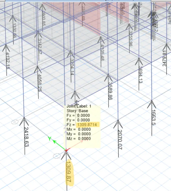
Total axial load on column C1 = 44.804 + 41.41 = 86.21 KN
Total axial load on C1 column = Number of floor X Load in first floor Column C1
= 15 X 86.21 = 1293.15 KN
Now we have almost got that same result from ETAB sodtware analysis= 1309.87 KN
d. Design of structural members
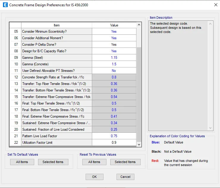
- Select appropriate parameters for the design of the members.
(Utilization factor kept as 0.9)
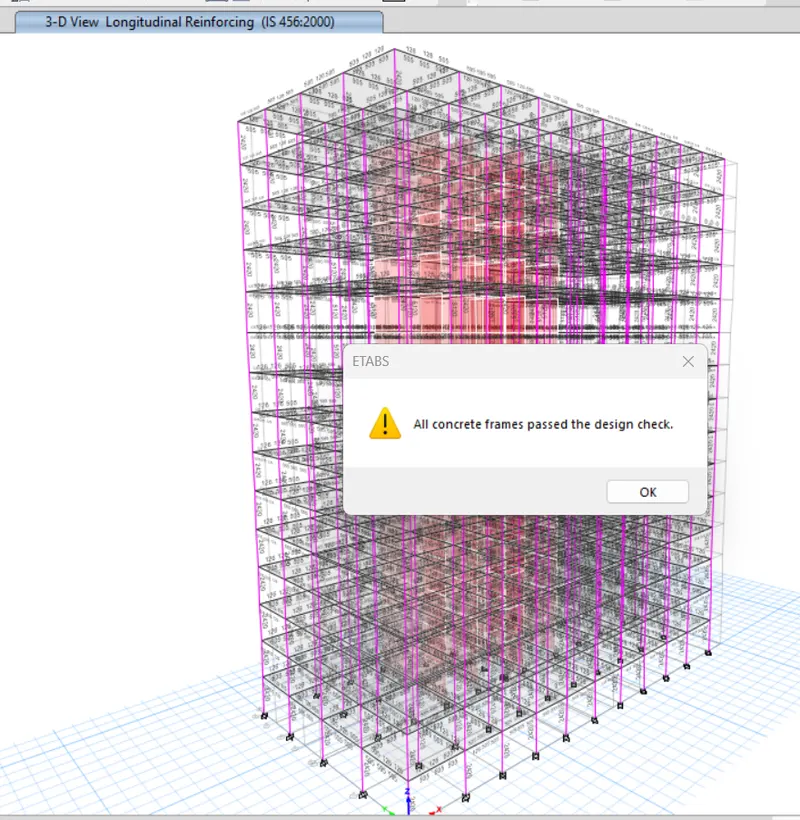
- Interpret the design results
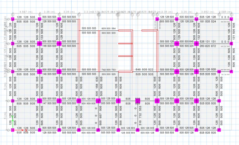
Beam longitudinal reinforcement detail
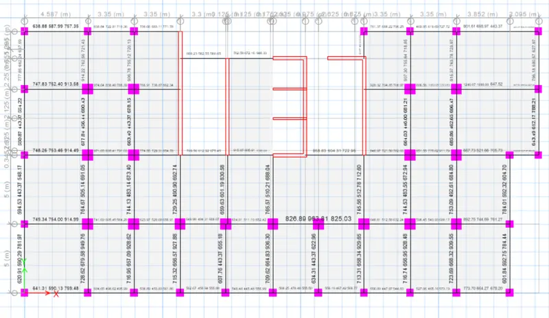
Beam shear reinforcement detail
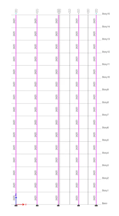
Column longitudinal reinforcement details-
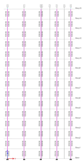
Column Shear reinforcement details
Shear Wall longitudinal reinforcement details
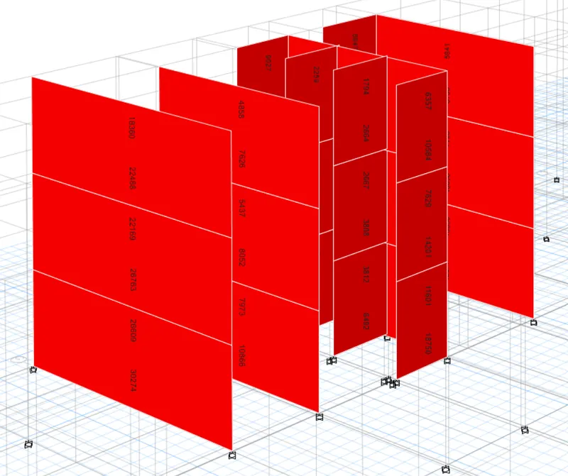
Pier Shear reinforcement details
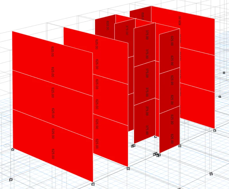
Result-
- Manual calculations for the base reactions in gravity load cases attached.
- Submit ETABS model with the complete model of the tall building (exported .e2k format, do not attach .EDB format directly)
- The model should pass all design and serviceability requirements.
- A comprehensive project report from the ETABS software (as PDF file)