Project-1: Modelling an electric Car with Li-ion battery
Aim : To make a simulink model of EV with DC motor and battery and it’s a rear-wheel-drive vehicle.
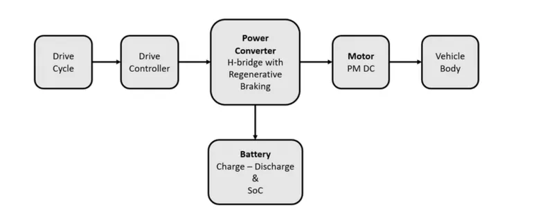
Block diagram of powertrain components in Electric Vehicle
Using 4 tyres and a vehicle body
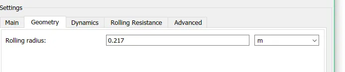
Gear Box, Tyre and Vehicle body Parameters:
Rolling radius: 0.217 m
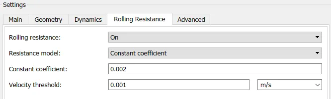
Coefficient constant: 0.002
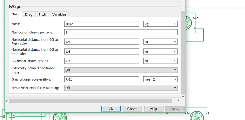
Mass: 1642 kgs
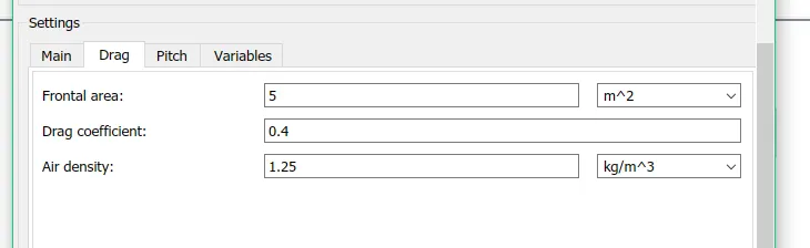
Frontal Area: 5m2
Drag Coefficient: 0.4
Air density: 1.25 kg/m3
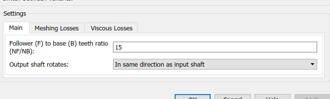
Gear ratio: 15
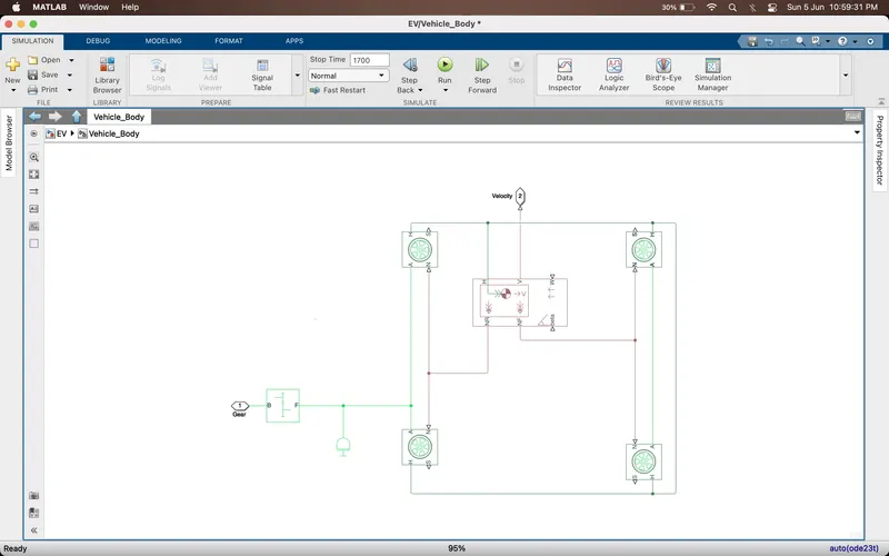
Where,
H – Hub, all are connected to 4 tyres respectively with the vehicle body hub
A – Axle, Rear axle is connected with 2 tyres and front axle with 2 tyres
N – force applied, input force by the vehicle body and N are connected in 2 ways respectively i.e., rear and front axle
NR- Rear output force from the vehicle body, its given as an input to rear axle
NF- Front output force from the vehicle body, its given as an input to front axle
V- velocity
w- wind speed
beta – angle of inclination on road
B – gear input from the driver
F-output and it’s connected to rear axle because it’s a rear-wheel-drive vehicle, if front wheel drive, then connected to front axle.
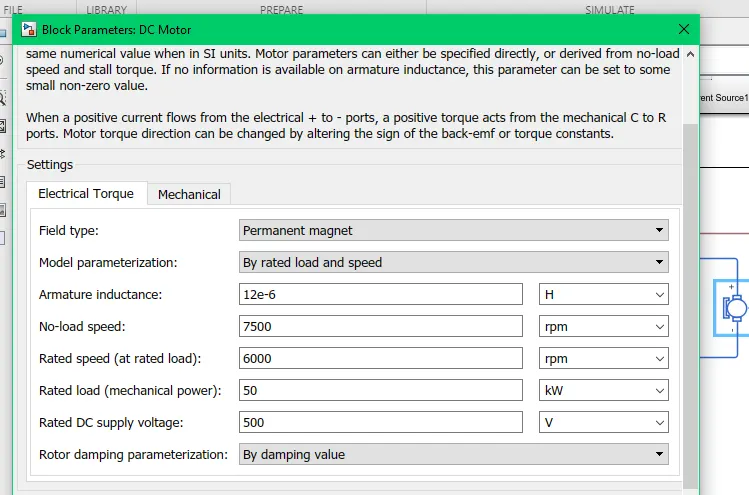
DC Motor Parameters: Selecting permanent magnet with rated load and speed
No Load: 7500 rpm
Rated Load: 6500 rpm
Rated mechanical Load: 50 KW
Rated DC supply voltage: 500V
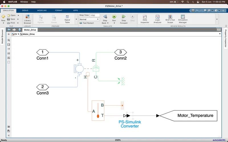
Where,
C is torque is connected to mechanical rotation reference
R is torque which connected as input to gear
Positive is given to current sensor
Negative is given to Electrical reference
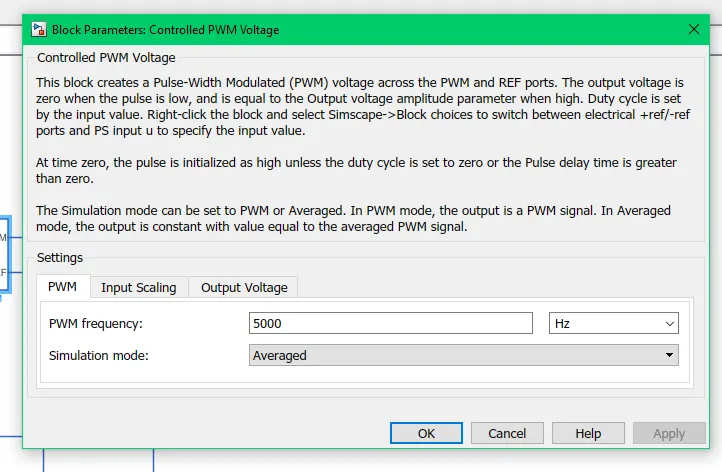
Power Converter Circuit: It is series combination of H- bridge and Controlled PWM voltage source
PWM frequency: 5000 Hz
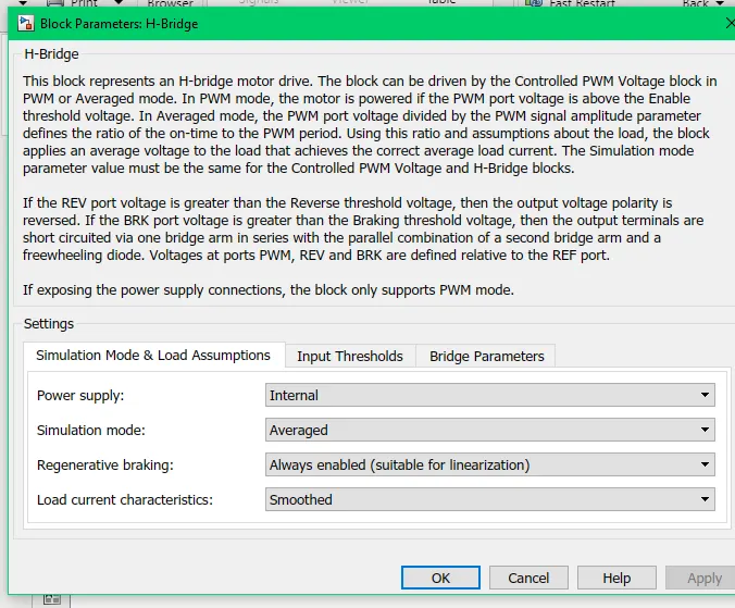
H-bridge parameters are chosen according
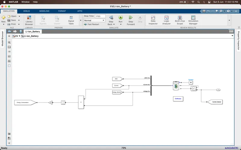
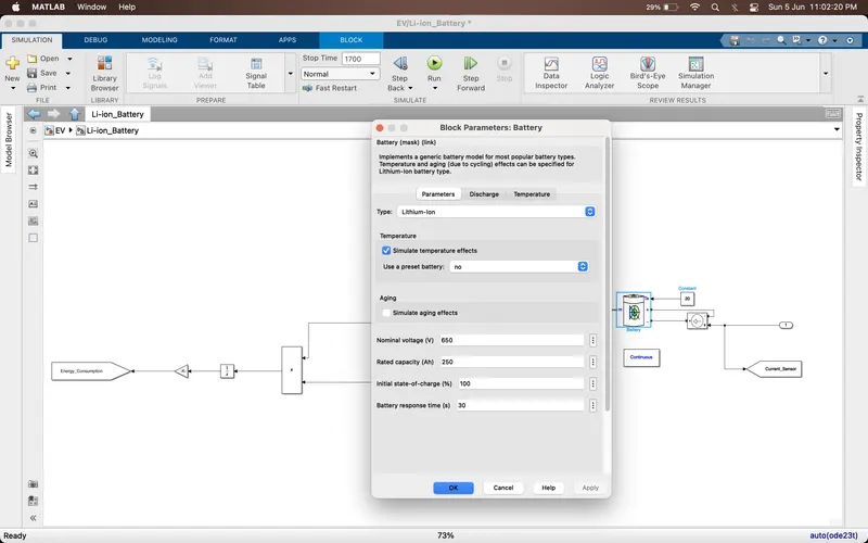
Battery Pack:
Nominal Voltage: 650V
Nominal Current: 250 Amp hr
PI Driver:
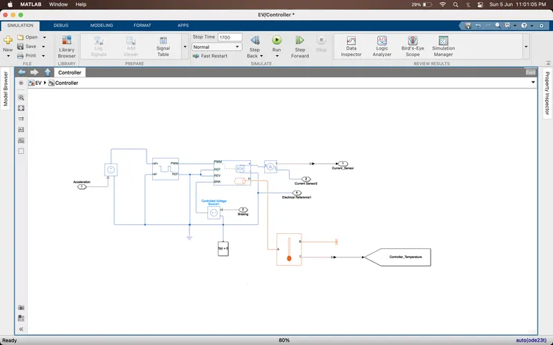
Acceleration is given as input to Controlled PWM voltage source
Deceleration/Braking is given as input to the H bridge as braking threshold voltage through a voltage-controlled source
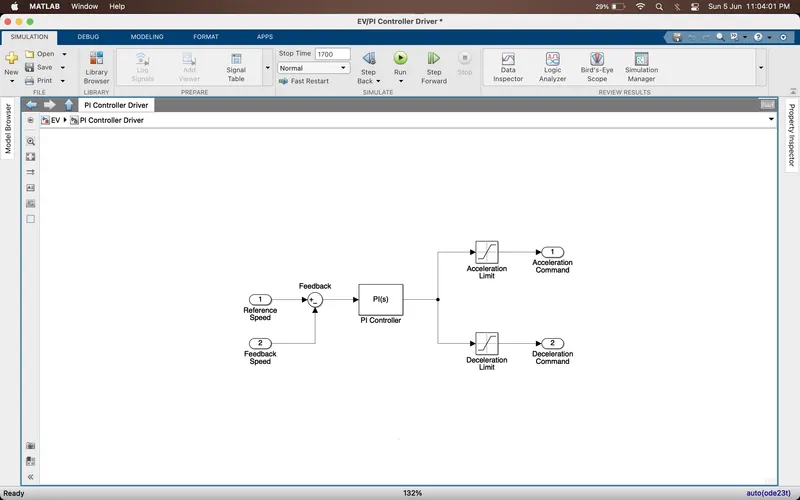
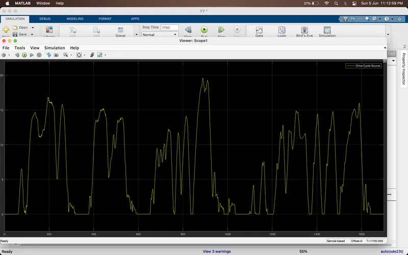
Veh Ref is Drive cycle
Vehicle velocity is given as the input to vehicle feedback
The function blocks used are as follows:
- Drive Cycle (City Suburban Heavy Vehicle Cycle)
- Constants
- PID Controller
- Simulink PS converter
- PS Simulink converter
- Inport
- Outport
- Saturation
- Subtract
- Mechanical Rotation Reference
- Electrical Reference
- Solver Configuration
- Controlled voltage source
- Controlled current source
- Controlled current sensor
- Battery
- Gain
- Bus Selector
- Temperature Sensore
- Thermal Reference
- Controlled PWM Voltage
- H bridge
- DC Motor
- Vehicle Body
- Tires
- Simple Gear
- Integrator
- Goto & From Tags
- Scope
- Display
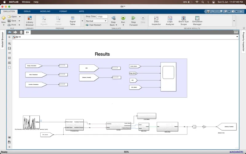
Results : Stimulation time for 1700 seconds
Drive cycle Input Source
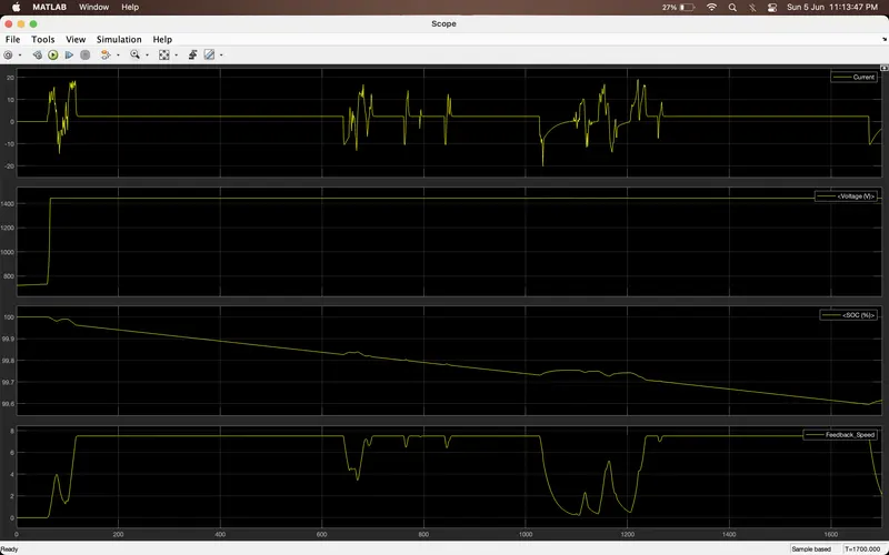
SOC is discharging from initial stage because the vehicle is in movement and current varies depending on the input to converter systems in the vehicle. We can also see that there is increase at some intervals of SOC and its is due to regenerative braking. The decrease in the feedback speed indicates the braking.
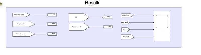
Distance travelled by the vehicle is 10.69 kms , SOC is 99.61% , Energy consumed is 1388
Conclusion :
- If the vehicle is designed for the same specifications as the matlab there would be some changes in the results depending on the surrounding and driver usage.
- Various parameters can be changed for better efficiency and improvement of the vehicle like Battery,mass of the vehicle,tyres, motor specifications etc
- From the model we have achieved the distance of 10.69kms and the discharge is also likely slower in discharge rate and it has only discharge 0.05%, we can say that the vehicle is efficient.