Project-1: Powertrain for aircraft in runways
- Listing out various aircraft’s total weight
|
Aircrafts |
Total Weight in kgs |
|
· Antanov AN-225 · Airbus A380-800 · Boeing 747-800 · Airbus A340-500 · Boeing 777-300ER · Boeing 787-10 · Boeing 737-900 · Airbus A320-100 · Embraer 190 · Gulfstream 650 · Bombardier CRJ900 · Bombardier Q400 · Learjet 75 · Cessna Citation CJ4 · Beechcraft King Air B100 · Diamond DA50 RG · Beechcraft Bonanza G36 · Cessna 206H · Sirrus SR22 · Cessna 172R |
· 640000 · 575000 · 447700 · 372000 · 352000 · 254000 · 85000 · 68000 · 48000 · 45200 · 36500 · 28000 · 9700 · 7800 · 5400 · 2000 · 1660 · 1630 · 1630 · 1100 |
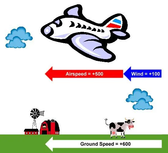
- Ground speed is the airplane’s speed relative to the surface of the earth whereas airspeed is its speed relative to the air it is flying in.
Difference between airspeed and groundspeed may vary depending on:
Yes, because if there is wind blowing then groundspeed is the sum of airspeed and windspeed.
No, if there is no wind then groundspeed is equal to airspeed.
- Due to following reasons
- Size of the aircraft, so there won’t be any wear and tear because the pilot cannot see the entire surrounding
- Because of the thrust, it may damage the surrounding or intake of debris and cause in failure of engine or any other parts
- Loud noise because of the powerful engine
- Saving fuel
- They need lot of force to move from halt because of the weight
- They can halt the aircraft at precise location without any hassle.
- Aircraft is pushed to runway either by taxiing or towing.
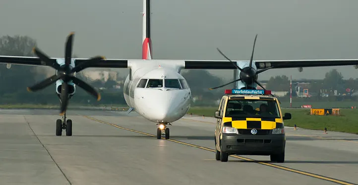
Taxiing: Taxiing is the movement of an aircraft on the ground on the yellow line, under its own power while on the surface. The taxiing has speed limit for moving the aircraft.
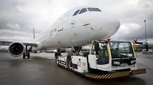
Towing: The forward movement of an aircraft usually with engines off using the power of a specialized ground attached or supporting the nose of landing gear.
- Take off Power: The amount of power that an engine is allowed to produce for a limited period of time for take-off. According to reciprocating engines, it is the brake horsepower developed under standard sea level conditions and under maximum conditions of the crankshaft rotation speed and engine pressure. According to gas turbine engines it is the thrust developed under static conditions at a specific altitude and atmospheric conditions of the rotor shaft rotational speed and gas temperature. Moreover, the power to take off depends on the weight, altitude, temperature and runway length to get desired take off power.
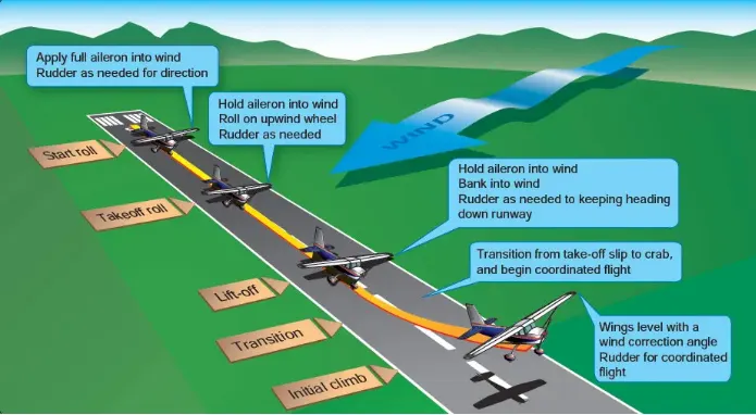
Tyre design: An aircraft tyre is designed to withstand extremely heavy loads for short durations. The number of tyres required for aircraft increases with the weight of aircraft, as the weight of the aircraft should be distributed evenly. The tread patterns are designed to facilitate stability in high crosswind conditions to channel away water to prevent hydroplaning and for braking effect.
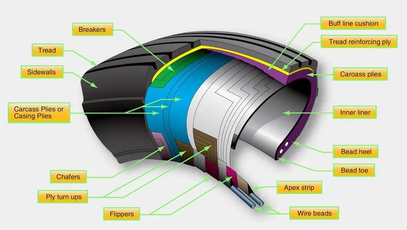
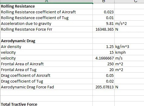
Rolling Resistance: Rolling resistance is the energy that your vehicle needs to send to your tyres to maintain movement at consistent speed over a surface. In other words, it’s the effort required to keep a tyre rolling. The main contributor to the rolling resistance is the process known as hysteresis. Hysteresis is essentially the energy loss that occurs as tyre rolls through its footprint.
Frr = µrr mg
Where Frr is the rolling resistance force
µrr = rolling resistance coefficient
m = mass of the vehicle
g = acceleration due to gravity
Tyre Pressure: The tyre pressure of an aircraft depends on number of tyres and weight of the aircraft under cold pressure. It is important to maintain the desired inflation pressure of the tyre or else it may result in damage of tyre. For aircrafts the pressure is 200-300 psi depends on the weight and number of tyres. Nitrogen is used for tyre inflation.
Braking force while landing: Following braking techniques are used to decelerate the aircraft i.e.,
- Aircraft disc brakes in the landing gear is used to brake the wheels while touching the ground. These brakes are operated hydraulically or pneumatically.
- Thrust reversers allows the thrust from the engines to be used to slow the aircraft.
- Air brakes dedicated flight control surfaces that work by increasing the drag.
- Large drogue parachutes are used by several former and current military and civilian aircraft.
- Assuming,
Mass of the aircraft = m1=640000 kgs
Rolling resistance of aircraft =µr = 0.023
Acceleration due to gravity = g=9.81 m/s2
Air density = ᵨ = 1.25 kg/m3
Drag coefficient of the aircraft = Ca = 0.05
Frontal Area of aircraft =A1= 250 m2
Mass of the tug = m2=2500 kgs
Rolling resistance of tug=µrt = 0.01
Drag coefficient of the tug =Ct=0.02
Frontal area of the Tug =A2=20 m2
Speed of the tug vehicle = v=15 kmph =15*5/18 =4.167 m/s
Where µrr = µr+ µrt
M = m1+ m2
A = A1+A2
Cd= Ca+Ct
Calculations :
Rolling Resistance Force = Frr =µrr *M * g
= (0.023+0.01)*(640000+2500)*9.81
=0.033 *642500*9.81
= 207.99652 KN
Aerodynamic Drag Force = Fad = 0.5*Cd*A*v2* ᵨ
= 0.5*(0.05+0.02)*(250+20)*(4.167)2 * 1.25
= 0.5*0.07*270*(4.167)2*1.25
= 205.078 N
Total Tractive Force = Fte = Frr +Fad
=207.99K +205.078
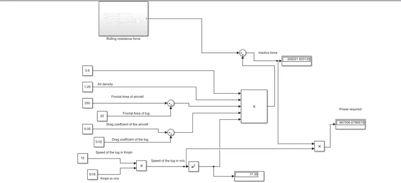
= 208.195 KN
Total Power=P= Fte *v
=208.195K*4.167
= 867.54 KW
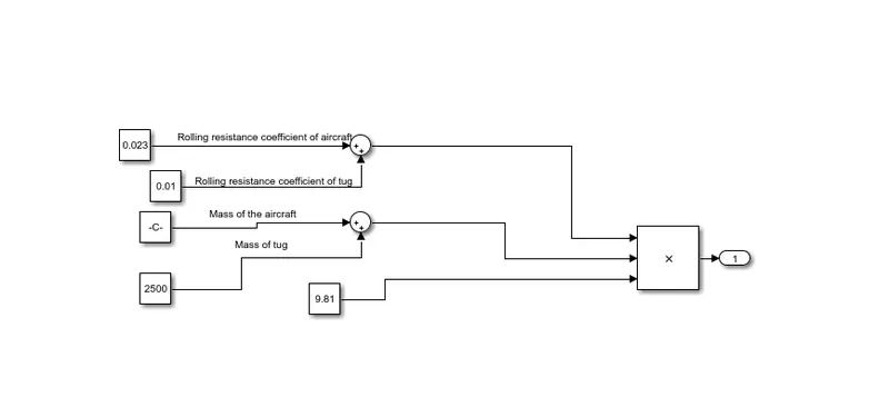
B . The matlab model is developed for the above calculated force and power.
Rolling resistance Force
7.
- Assuming,
Mass of the aircraft = m1=48000 kgs
Rolling resistance of aircraft =µr = 0.023
Acceleration due to gravity = g=9.81 m/s2
Air density = ᵨ = 1.25 kg/m3
Drag coefficient of the aircraft = Ca = 0.05
Frontal Area of aircraft =A1= 250 m2
Mass of the tug = m2=2500 kgs
Rolling resistance of tug=µrt = 0.01
Drag coefficient of the tug =Ct=0.02
Frontal area of the Tug =A2=20 m2
Speed of the tug vehicle = v=15 kmph =15*5/18 =4.167 m/s
Where µrr = µr+ µrt
M = m1+ m2
A = A1+A2
Cd= Ca+Ct
Calculations :
Rolling Resistance Force = Frr =µrr *M * g
= (0.023+0.01)*(48000+2500)*9.81
=0.033 *50500*9.81
= 16.348 KN
Aerodynamic Drag Force = Fad = 0.5*Cd*A*v2* ᵨ
= 0.5*(0.05+0.02)*(250+20)*(4.167)2 * 1.25
= 0.5*0.07*270*(4.167)2*1.25
= 205.078 N
Total Tractive Force = Fte = Frr +Fad
=16.348K +205.078
= 16.5534 KN
Total Power=P= Fte *v
=16.5534K*4.167
= 68.97 KW
The Torque-speed relation is T=24.7+0.0051w^2
Taking the Reb 90 electric motor with 80KW power,400-800V,T=300Nm,107 hp
Duty cycle = Output Power/Input Power
= 68.97/80 = 86.21%
| Parameters | SI unit |
|
|
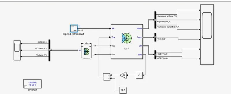
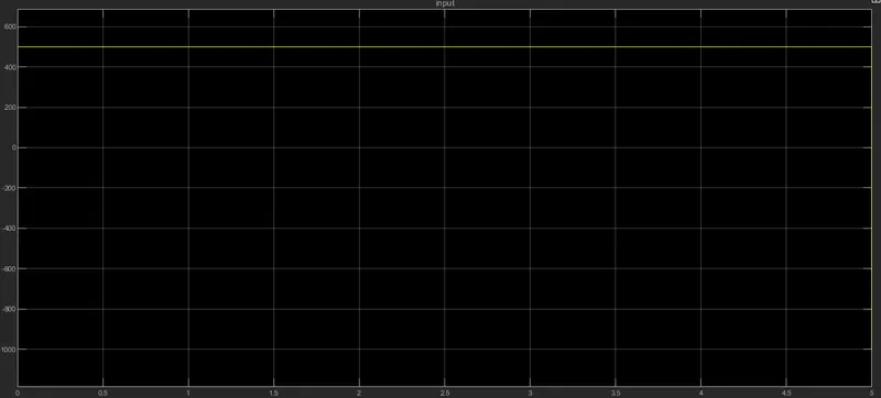
Stimulation time = 5 seconds
Input voltage
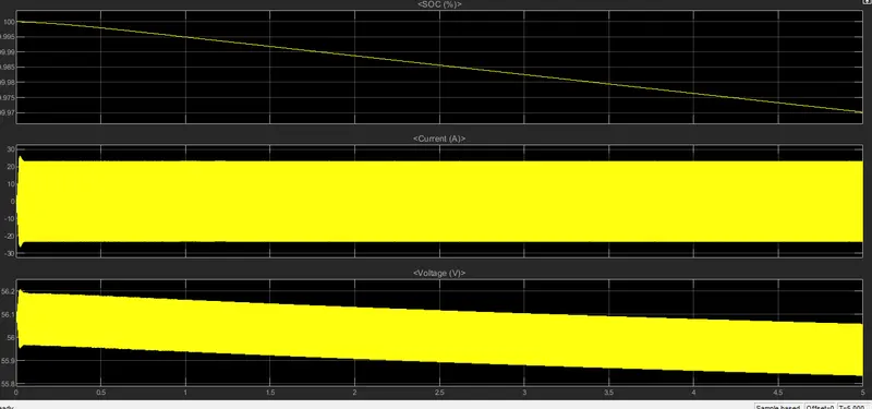
Output results
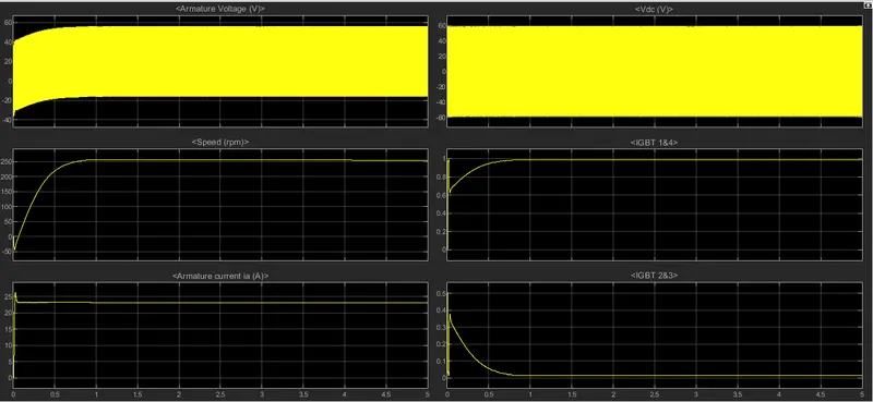
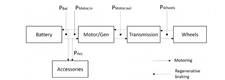
Block diagram of Powertrain :
B .Excel file is attached