Project-1: Modelling an electric Car with Li-ion battery
Aim: To build an Electric Rickshaw model for the Electric Vehicle.
Objectives:
- To build a simple low run-time modelling using Simulink
- To check out performance parameter: Speed, SOC of various drivecycle for an Electric Vehicle.
Methodologies:
Any Electric Vehicle consists of an Electric Motor, Motor Controller, Batteries and Drivetrain. Hence the flow of work will be as follows:
- To identify the propulsion power required.
- To select the motor type and ratings according to the power required.
- To select the battery type and the battery rating according to the need of the Electric vehicle.
Study:
The general Electric Vehicle has
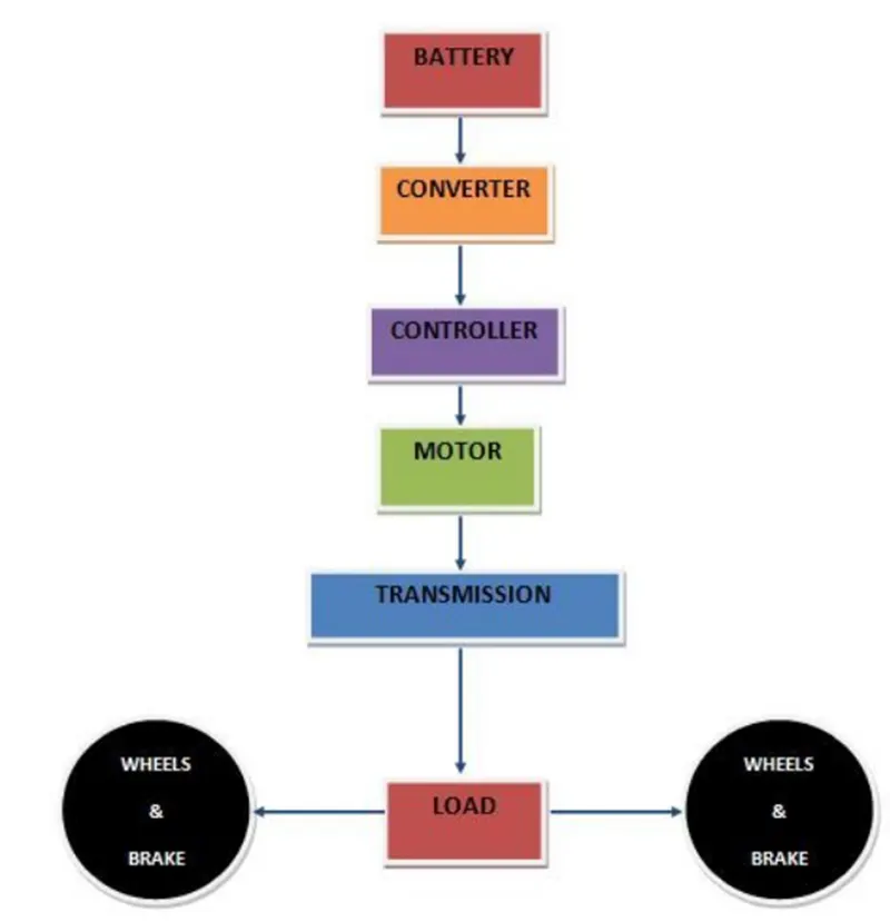
this no. of main components.
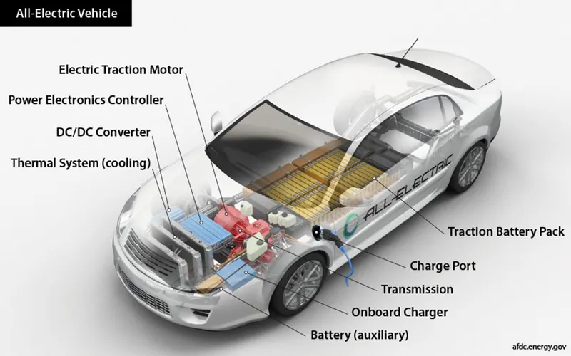
A General Electric Vehicle is usually looks like this:
Let’s look into the Simulation model we have built:
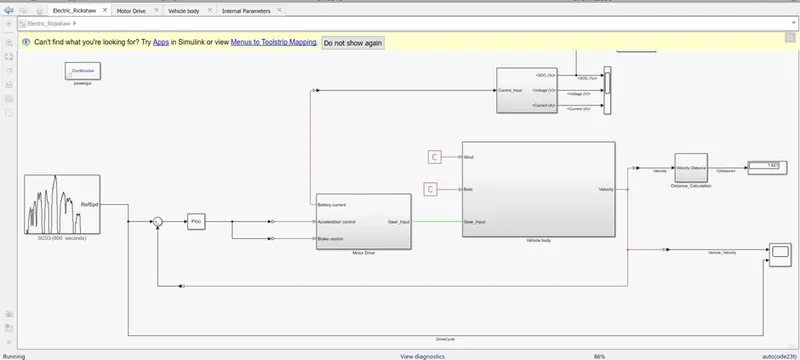
Now, we start from the input of the Electric Vehicle which is the Drive cycle.
Drive Cycle
Drive Cycle block is nothing but a Speed variation with respect to time. Some of the standard driving cycles can be tested using this block.
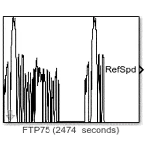
For our case we choose the US06 drive cycle. The Dive cycle looks like this:
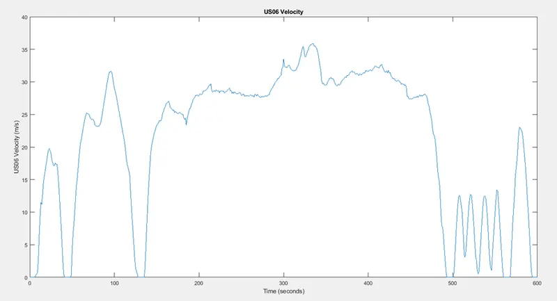
Since the drive cycle is 600 sec so, our simulation time is set to 600sec.
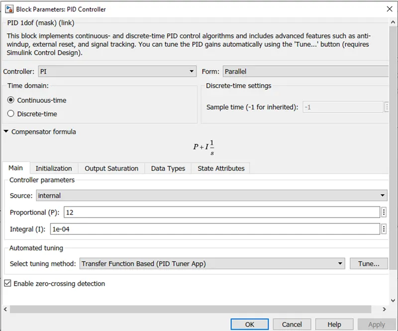
For the Driver we have chosen a PI controller which takes the difference of the speed to follow with the actual speed of the vehicle and gives the output to the acceleration command and the brake command.
The PI parameters.
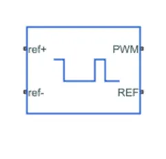
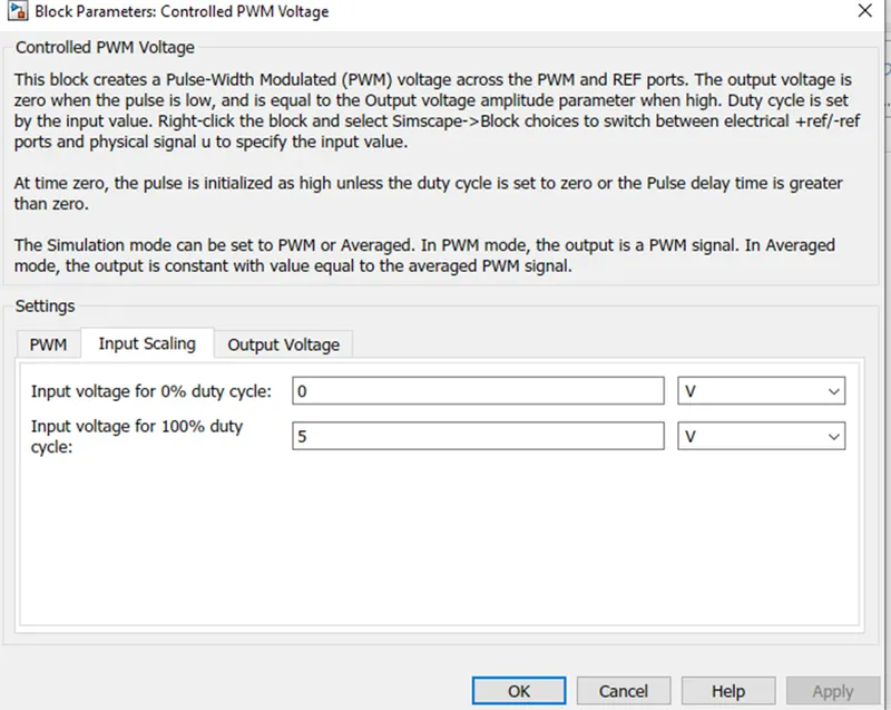
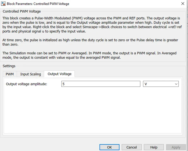
Controlled PWM Voltage source:
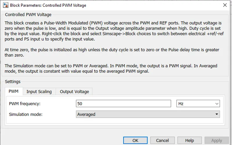
This block creates a PWM voltage across the terminal. This signal is inputed to the H-bridge.
The parameters of the PWM voltage is
H-Bridge:
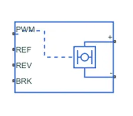
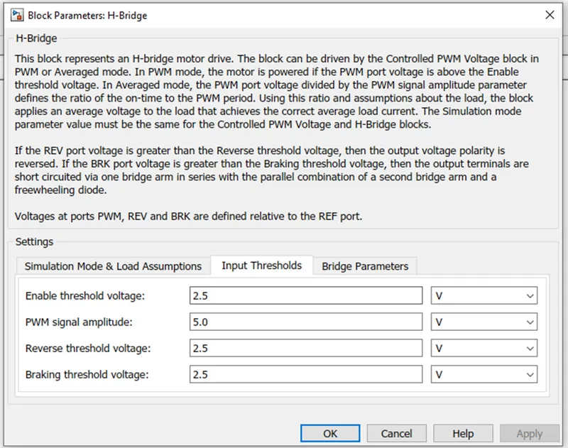
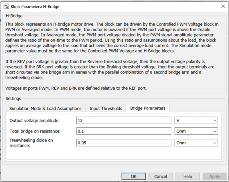
H-bridge is a 2-legged configuration where every leg has 2 switches. This acts as a Motor drive which can be controlled by the PWM voltage source.
The parameters of the H-bridge are:
DC Motor:
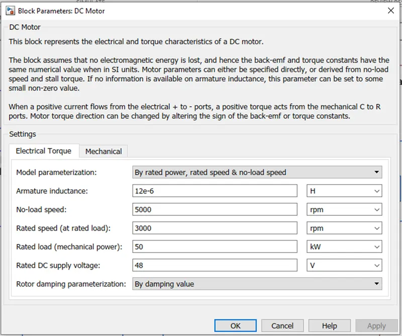
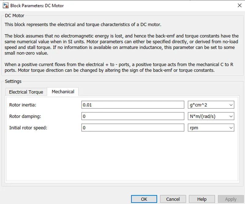
We have chosen Permanent Magnet DC motor as traction motor for the Electric Vehicle. The parameters of the DC motor are shown below:
Powertrain:
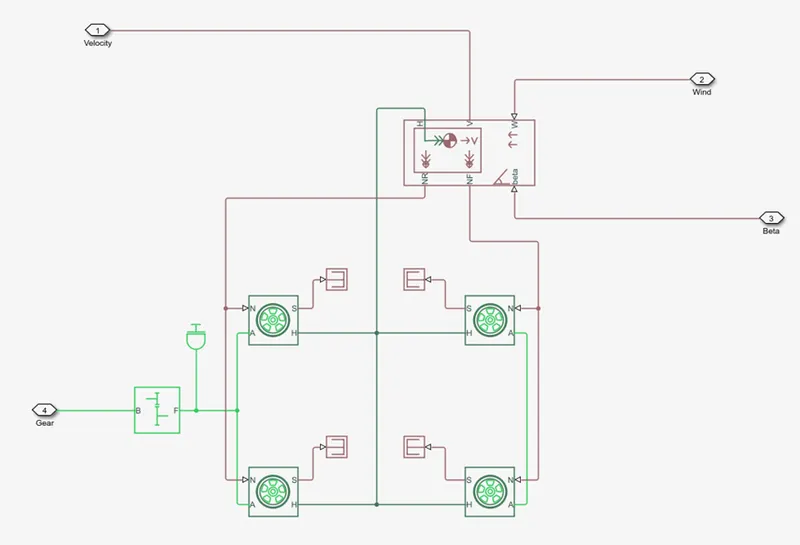
The chassis of the Electric Powertrain consists of the Vehicle body and the 3 tires. For the rear wheels the axles are interconnected and a gearbox is connected with the axle. The Hub port (H) of all the 3 wheels are connected together and are connected to the vehicle body. The rear wheel N port are connected together with the NR port of the vehicle which represents the force acting on the wheels. The N port of the front wheel is also connected with the NF port of the vehicle body.
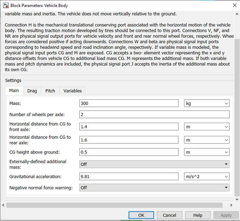
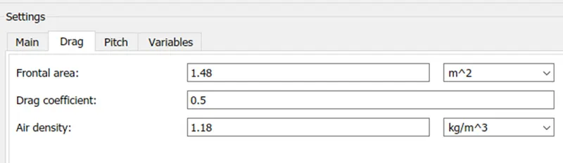
The Vehicle body parameter:
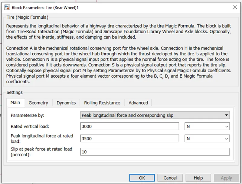
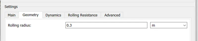
Tire Parameter:
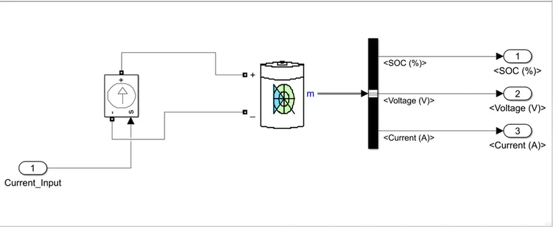
Battery:
The battery supplies the power to the Electric Motor. The Battery here works on the current required by the motor and hence it is connected in parallel with
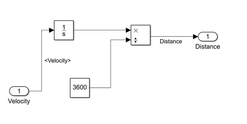
Distance calculation:
Results:
Here we have considered the US06 driving cycle for the Electric Vehicle operation
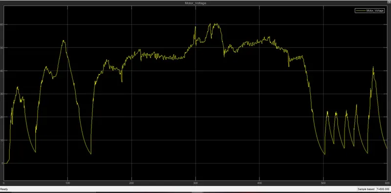
The voltage of the output of the controlled PWM voltage is shown below
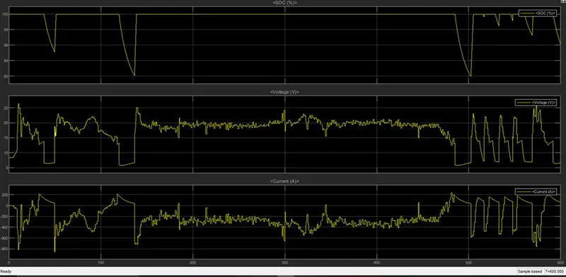
The Battery Characteristics are shown below:
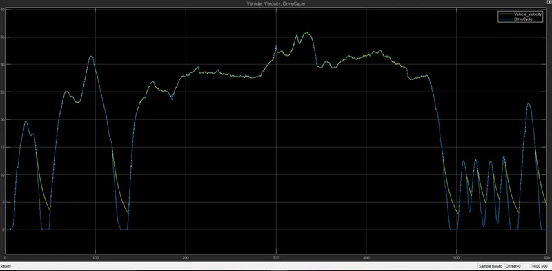
The vehicle speed characteristics are shown below:
Conclusion:
- From our simulation result we can see the vehicle is following the input drivecycle. But there are some cases where it is failed to follow the drivecycle. This is due to the sudden brakes of the system. In our model there is no mechanical braking is used. So the only braking option available is the Electrical braking. But in case of steep braking mechanical braking is required and hence the vehicle fails to put a stop.
- From the SOC characteristics we can see there is regenerative braking.