Project-1: Modelling an electric Car with Li-ion battery
Modelling an electric Car with Li-ion battery
AIM:
Create a MATLAB model of electric car which uses lithium ion battery and suitable motor. Choose suitable blocks from Simscape or Powertrain block set. Implement the vehicle speed control using PI controller and generate brake and accelerator commands. Avoid using readymade driver block for speed control.
Theory :
An Electric Vehicle (EV) is a vehicle that uses one or more electric motors or traction motors for propulsion. An electric vehicle may be powered through a collector system by electricity from off-vehicle sources, or may be self-contained with a battery, solar panels, fuel cells or an electric generator to convert fuel to electricity. EVs include, but are not limited to, road and rail vehicles, surface and underwater vessels, electric aircraft and electric spacecraft.
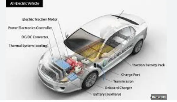
- EVs have no need for the fuel engine and gear transmission, the two of the most crucial components for internal combustion vehicles.
- An electric powered car has three primary components - Battery, motor controller, and the electric motor.
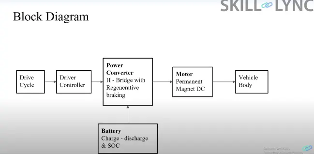
Block diagram :
Components :
The main components of modelling an EV are:
- Vehicle body
- Motor & motor controllers
- Power converters
- Batteries
- Drive cycle
Vehicle body
This section is intended to give guidance on the design of chassis for electric vehicles. Chassis design should be carried out in conjunction with other texts on chassis design, not to mention computer packages that specialise in this area. Nevertheless a basic understanding of what the chassis should do and other parameters related to electric vehicle chassis is needed.
In the early cars chassis and bodies were separate items. The chassis gave the basic strength of the vehicle while the body and glazing acted as a cocoon to keep the passengers and luggage protected from the outside elements.
In recent times the body and chassis have been combined as a monocoque so that every part, including the glazing, adds to the strength and stiffness, resulting in a much lighter vehicle. Either monocoques or separate chassis/body units are an acceptable basis for design. Despite the popularity of monocoques, several modern electric vehicles use a separate chassis, most notably the advanced new General Motors Hy-wire fuel cell vehicle, which will be discussed in more detail later.
It is worth pausing to think precisely what the chassis/body does; ideally a chassis/body should fill the following criteria. It should:
• not vibrate, particularly at frequencies and harmonics of rotating parts;
• be aerodynamic;
• be resistant to impact;
• crumple evenly in an accident, minimising forces on driver/passengers;
• be strong enough to fix components to easily;
• be impact and roll resistant;
• be aesthetically pleasing;
• be corrosion-proof.
DC MOTOR:
A DC motor is an electrical machine that converts electrical energy into mechanical energy. In a DC motor, the input electrical energy is the direct current which is transformed into the mechanical rotation.
From the above definition, we can conclude that any electric motor that is operated using direct current or DC is called a DC motor. We will understand the DC motor construction and how a DC motor converts the supplied DC electrical energy into mechanical energy in the next few sections.
DC Motor Diagram
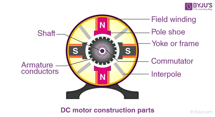
Armature or Rotor
The armature of a DC motor is a cylinder of magnetic laminations that are insulated from one another. The armature is perpendicular to the axis of the cylinder. The armature is a rotating part that rotates on its axis and is separated from the field coil by an air gap.
Field Coil or Stator
A DC motor field coil is a non-moving part on which winding is wound to produce a magnetic field. This electro-magnet has a cylindrical cavity between its poles.
Commutator and Brushes
Commutator
The commutator of a DC motor is a cylindrical structure that is made of copper segments stacked together but insulated from each other using mica. The primary function of a commutator is to supply electrical current to the armature winding.
Brushes
The brushes of a DC motor are made with graphite and carbon structure. These brushes conduct electric current from the external circuit to the rotating commutator. Hence, we come to understand that the commutator and the brush unit are concerned with transmitting the power from the static electrical circuit to the mechanically rotating region or the rotor.
DC Motor Working
In the previous section, we discussed the various components of a DC motor. Now, using this knowledge let us understand the working of DC motors.
A magnetic field arises in the air gap when the field coil of the DC motor is energised. The created magnetic field is in the direction of the radii of the armature. The magnetic field enters the armature from the North pole side of the field coil and “exits” the armature from the field coil’s South pole side.
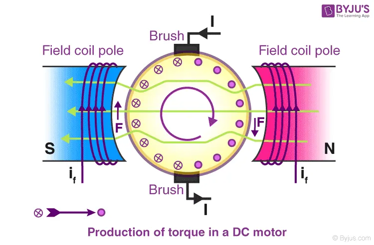
The conductors located on the other pole are subjected to a force of the same intensity but in the opposite direction. These two opposing forces create a torque that causes the motor armature to rotate.
|
Working principle of DC motor When kept in a magnetic field, a current-carrying conductor gains torque and develops a tendency to move. In short, when electric fields and magnetic fields interact, a mechanical force arises. This is the principle on which the DC motors work. |
Battery:
Lithium ion battery is used in this electric vehicle four wheeler car.
Lithium-ion batteries are popular because they have a number of important advantages over competing technologies:
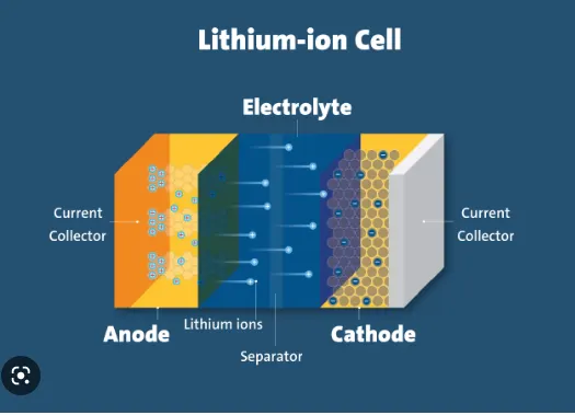
- They're generally much lighter than other types of rechargeable batteries of the same size. The electrodes of a lithium-ion battery are made of lightweight lithium and carbon. Lithium is also a highly reactive element, meaning that a lot of energy can be stored in its atomic bonds. This translates into a very high energy density for lithium-ion batteries. Here is a way to get a perspective on the energy density. A typical lithium-ion battery can store 150 watt-hours of electricity in 1 kilogram of battery. A NiMH (nickel-metal hydride) battery pack can store perhaps 100 watt-hours per kilogram, although 60 to 70 watt-hours might be more typical. A lead-acid battery can store only 25 watt-hours per kilogram. Using lead-acid technology, it takes 6 kilograms to store the same amount of energy that a 1 kilogram lithium-ion battery can handle. That's a huge difference [source: Everything2.com].
- They hold their charge. A lithium-ion battery pack loses only about 5 percent of its charge per month, compared to a 20 percent loss per month for NiMH batteries.
- They have no memory effect, which means that you do not have to completely discharge them before recharging, as with some other battery chemistries.
- Lithium-ion batteries can handle hundreds of charge/discharge cycles.
That is not to say that lithium-ion batteries are flawless. They have a few disadvantages as well:
- They start degrading as soon as they leave the factory. They will only last two or three years from the date of manufacture whether you use them or not.
- They are extremely sensitive to high temperatures. Heat causes lithium-ion battery packs to degrade much faster than they normally would.
- If you completely discharge a lithium-ion battery, it is ruined.
- A lithium-ion battery pack must have an on-board computer to manage the battery. This makes them even more expensive than they already are.
- There is a small chance that, if a lithium-ion battery pack fails, it will burst into flame.
Simlink model:
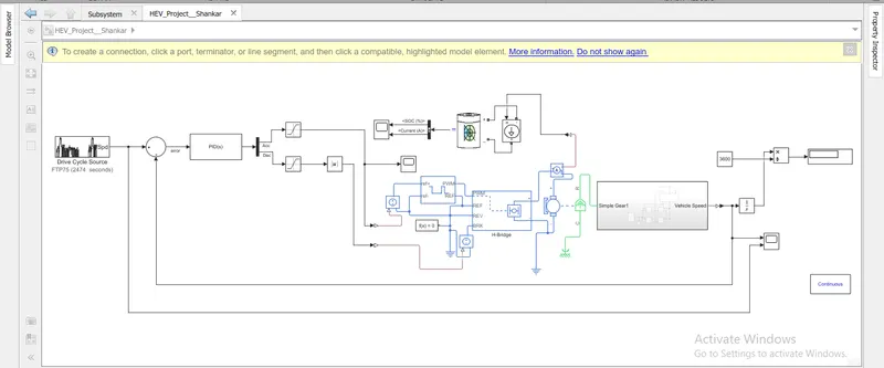
Subsystem of chasis :
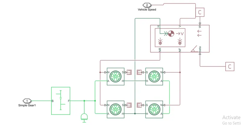
Tire :

- Totally there are 4 tires present in the vehicle.
- Rolling resistance force is created in the tire when the vehicle moves.
- Front 2 tires is connected with front axle and rear tyre is connected with rear axle,
- There are totally 4 input ports, they are
- N - Phisical signal input port that applies normal force applied on the tire.
- S - Phisical signal output port that reports the tire slip.
- A - mechanical rotational conversing port for the wheel axle.
- H - Thrust developed by the tire.
Vehivcle body:
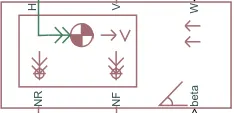
- Body chasis is the important part of each and every vehicle.
- H - mechanical translational conserving port hub
- V - actual output translational velocity of the vehicle.
- W - headwind speed
- NR - correspond to the output ports for nomral reaction forces on rear axle wheels respectively.
- NF - correspond to the output ports for nomral reaction forces on front axle .
- beta - is the road inclination angle.
The geometric parameters of the vehicle are given as
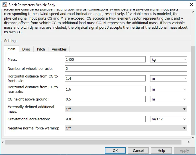
- Total mass is 1400 kgs.
- Other parameters are mentioned below.
Drag:
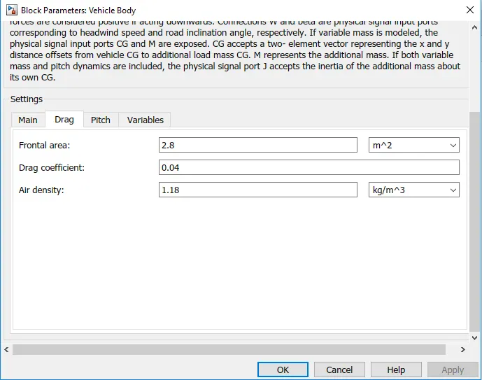
- Drag co-efficient is 0.04.
- Frontal area is 2.8 m^2.
Gear ratio:
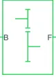
- A simple gear block is used to connect the motor to the rear axle of the vehicle.
- It represents the gearbox which connects the input shaft to the base gear and ouput from the foller gear.
Conserving Ports:
- B - port associated with input shaft (motor shaft)
- F - port associated with ouput shaft (axle / differential)
Simple Gear Parameters:
- Gear ratio and output direction is modified.
- Meshing loss is kept constant and gear is having a constant efficiency throughout the simulation.
- Viscous losses and faluts are kept at default conditions.
DC motor:
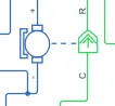
This is the DC Motor which would give the rotational power to the wheels and become the sole power generation source.
The DC Motors terminals are connected as mentioned below,
+ = Electrical signal to the motor Positive Terminal
- = Electrical signal to the motor Negative Terminal
R = Casing of the Motor connected with the Mechanical Rotational Reference Block
C = Rotor Case connected to the Mechanical Rotational reference
The geometric parameters of the DC motor are given as
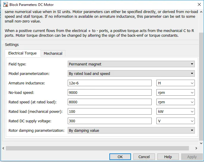
Mechanical of dc motor:
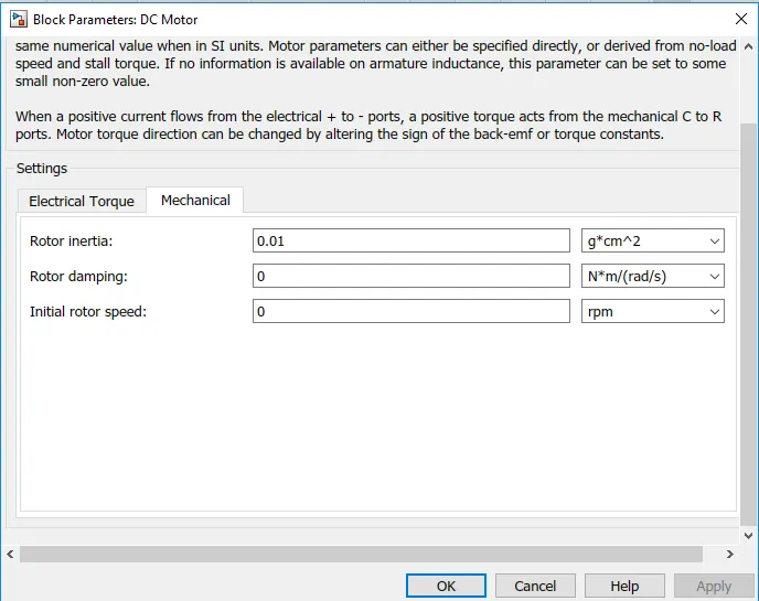
Here the momoent of inertia is taken as 0.01 gcm^2
H - bridge:
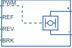
The H-Bridge helps in controlling the power that is input according to the requirement. The output provided are converted voltage as per the controlled parameters.
The geometric parameters of the H-bridge are given as
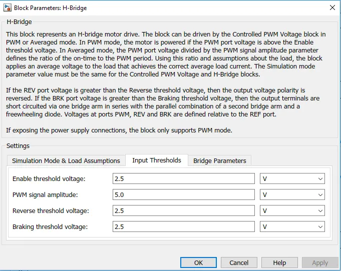
Bridge parameters:
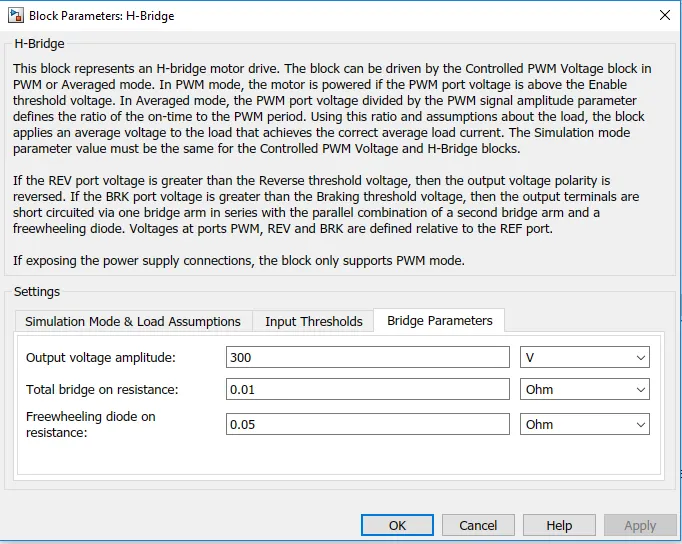
Output voltage amplitude is 300v.
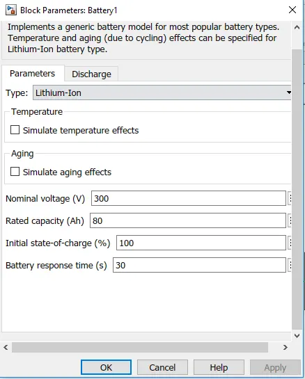
Battery:

The battery is connected as the power source to the model so that the power could be generated and the same power is transmitted accordingly to all the operating sources.
The terminals connected are to,
+ = The positive terminal of the operating sources
- = The negative terminal of the operating sources.
PWM controller:

- This block craetes voltage across the PWM and REF port.
- The output voltage is zero when the puse is low and equal to the output voltage amplitude parameter when high.
- Duth cycle is set by input value.
ref+ = Reference Positive connected with the Acceleration Commands from the Driver Model
ref- = Reference Negative connected with the Deceleration Commands from the Driver Model
PWM = PWM connected directly to the H-Block
REF = REF connected directly to the H-Block
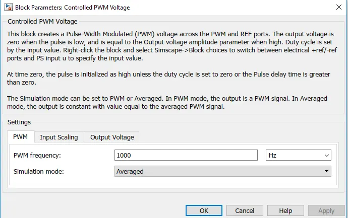
PWM frequency is setted to 1000Hz.
PID controller:
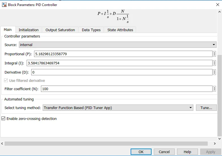
Here PID controller is used to control the vehicle.
The system is in non linear form.
So the PID controller is tuned by itself manually.
After tuned by PID controller system becames in linesr form.
Drive Cycle :
starting with the Drive Cycle,let consider a FTP75 for the operation of the Cycle in which the test duration would be 2474 seconds.
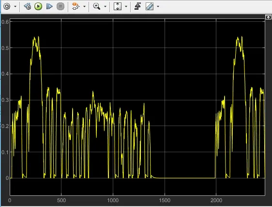
Reference Speed v/s Actual vehicle speed:
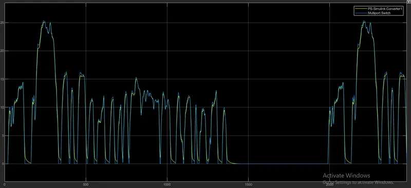
Wave is compared to the drive cycle.
Wave is increased and decreased due to the acceleration and decelaration.
Actual speed is compared to the reference speed of the drive cycle.
Vehicle is running at the constant from 1400 to 2000 seconds.