Project-1: Modelling an electric Car with Li-ion battery
Q.1 answer
Create a MATLAB model of electric car which uses a battery and a DC motor. Choose suitable blocks from Powertrain block set.
OBJECTIVES: 1. System level configurations
2. Model parameters
3. Results
4. Conclusion
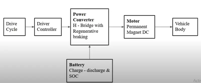
BLOCK DIAGRAM:
INTRODUCTION OF ELECTRIC VEHICLES:
- An electric vehicle (EV) is one that operates on an electric motor instead of an internal combustion engine that generates power by burning a mix of fuel and gases.
- Therefore, such a vehicle is seen as a possible replacement for current-generation automobiles
- In order to address the issue of rising pollution, global warming, depleting natural resources, etc.
- Though the concept of electric vehicles has been around for a long time,
- It has drawn a considerable amount of interest in the past decade amid a rising carbon footprint and other environmental impacts of fuel-based vehicles.
- While some EVs used lead-acid or nickel-metal hydride batteries, the standard for modern battery electric vehicles is now considered to be lithium-ion batteries as they have greater longevity and are excellent at retaining energy, with a self-discharge rate of just 5% per month. Despite this improved efficiency, there are still challenges with these batteries as they can experience thermal runaway, which has, for example, caused fires or explosions in the Tesla Model S, although efforts have been made to improve the safety of these batteries.
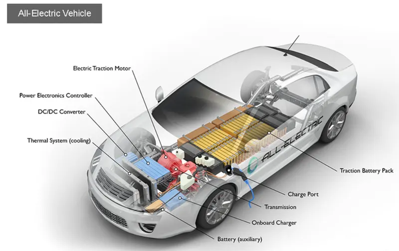
FULLY ELECTRIC:
- Can be charged at home overnight, providing enough range for average journeys.
- However, long journeys or those that require a lot of hill climbs may mean that the fuel cells require charging before you reach your destination
- although regenerative braking or driving downhill can help mitigate against this by charging the battery packs.
- Charging ranges from 30 minutes and up to more than 12 hours. This all depends on the speed of the charging station and the size of the battery.
ADVANTAGES OF BATTERY ELECTRIC VEHICLES(BEV):
- Creates very little noise
- No exhaust, spark plugs, clutch, or gears
- Doesn't burn fossil fuels, instead uses rechargeable batteries
PLUG-IN HYBRID ELECTRIC VEHICLE:
- Hybrid electric vehicles offer a mixture of battery and petrol or diesel power.
- This makes them better for traveling long distances as you can switch to traditional fuels rather than having to find charge points to top up the battery.
- The same disadvantages that apply to combustion engine vehicles also apply to PHEVs
- Need for more maintenance, engine noise, emissions and the cost of petrol.
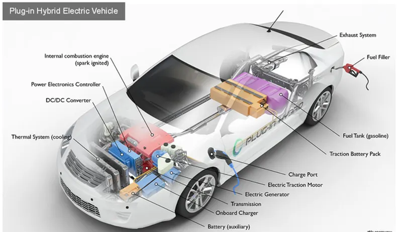
THE MAIN COMPONENTS OF THE ELECTRIC VEHICLE ARE:
- Wheels/tire
- Battery
- Motor/generator
- Motor controllers
- Power converters
- Transmission systems
Create a MATLAB model of an electric car:
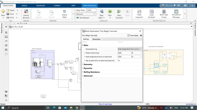
Tires:
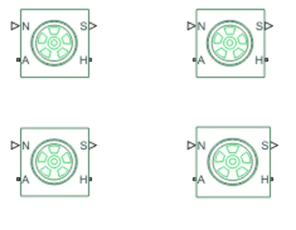
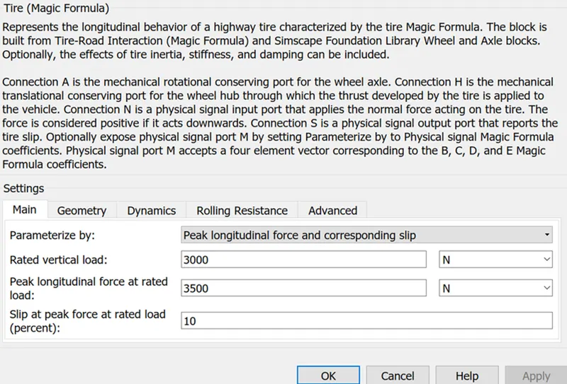
- N- WE need to apply a normal force
- A is nothing but an axle
- H is Nothing but a hub
- S stands for slip
- Total tire for a vehicle two of front and other two tires have the rare side of the vehicle connected with the vehicle body
VEHICLE BODY:
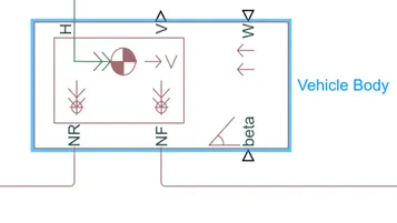
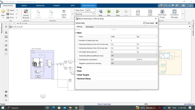
This block contains 6 ports that can be used in various aspects
- H- H Stand for hub it is used to connect the hub of wheels to the main body of the vehicle
- V- Physical signal output port of velocity is used the velocity output of the vehicle
- W- Physical input port used to wind velocity acts against the vehicle
- NR- Physical signal output port used to connect the rare wheels
- NS-Physical signal output port used to connect the front wheels
- Beta- physical signal input port which allows the vehicle to undergo an inclination of hill-climbing force
SIMPLE GEAR:

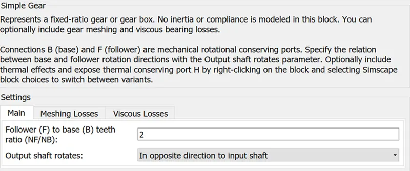
This block model a gear system with a fixed-gear ratio with non-inertial effects. However, we can modify the messing of the gear teeth here the follower to base teeth ratio has been set to 2 and the output shaft rotates in the same direction as the input shaft.
POWER BLOCKS:
H-BRIDGES:
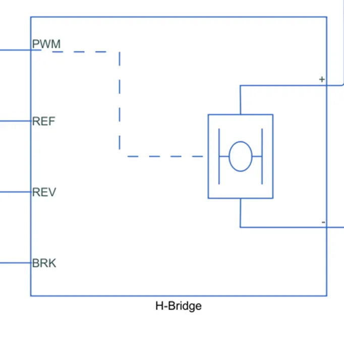
- Create an H-bridge block and double click on it and change the simulation mode to averaged
- create current sensor block connect positive to positive and negative to negative of the dc motor port
- The REV and REF OF the H bridge are connected to the solver configuration.
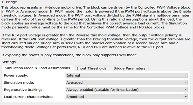
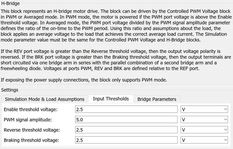
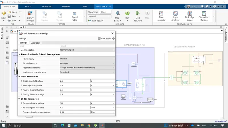
The H-Bridge block represents an H-bridge motor driver. The block has the following two Simulation mode options. If the input signal has a value greater than the Enable threshold voltage parameter value, the H-Bridge block output is on and has a value equal to the value of the Output voltage amplitude parameter. The H-Bridge block drives the motor. In this example, all input ports of the H-Bridge block except the PWM port are connected to the ground. As a result, the H-Bridge block behaves as follows: When the motor is on, the H-Bridge block connects the motor terminals to the power supply.
CONTROLLED PMW VOLTAGE:
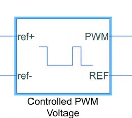
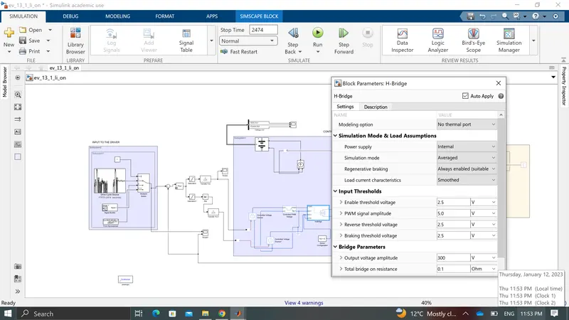
The H-Bridge block output is a controlled voltage that depends on the input signal at the PWM port. If the input signal has a value greater than the Enable threshold voltage parameter value, the H-Bridge block output is on and has a value equal to the value of the Output voltage amplitude parameter.
DC MOTOR:
 '
'
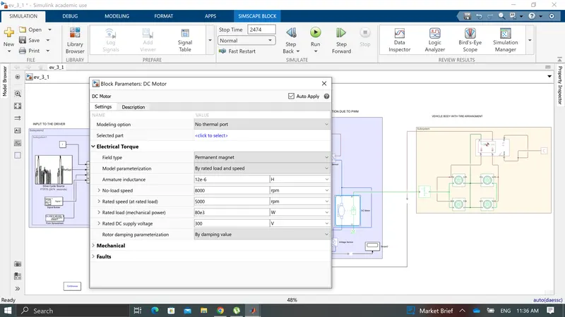
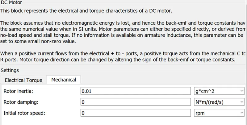
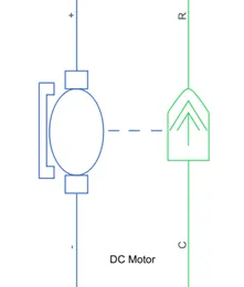
This block is used in the DC Motor Position: Simulink Modelling section. In order to simulate the response of this system, it is further necessary to add sensor blocks to the model to simulate the measurement of various physical parameters and a voltage source to provide excitation to the motor.
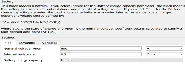
BATTERY:
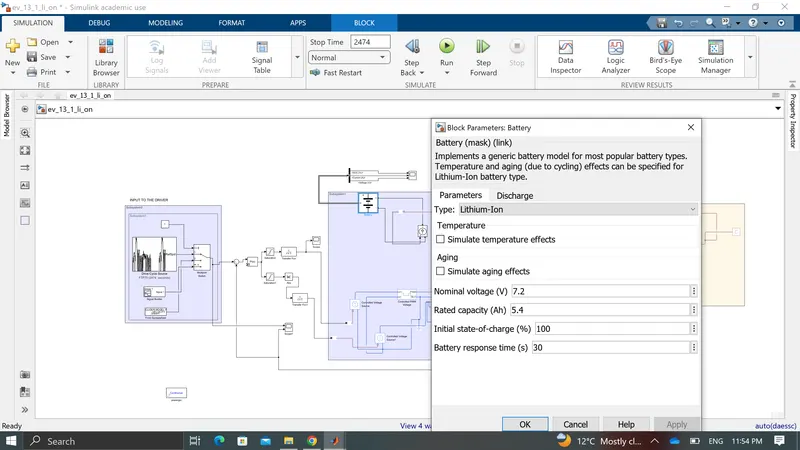
- The positive terminal of the battery is connected to the positive port of the controlled current source and the negative terminal is connected to the negative port of the controlled current source
- The physical signal of the controlled current source is connected to a PS-Simulink converter to connect to go block
- connect integrator to the gain block such that ampere-hour is converted to ampere sec
- and connect it sum block with constant 1
- Create Go block name it as SOC.
STATE OF CHARGE:
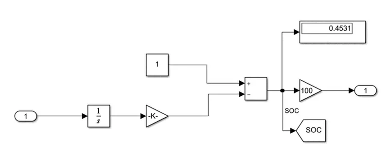
To measure the state charge of the battery. the integrator block is used to handle data transfer and integrate the value of the current signal with respect to time then gain block is used in order to multiply divide the signal coming from the integrating block. this block will divide a current signal with the ampere rating battery which is 160(ah)*3600(sec). Assuming the battery is always fully charged i have added a constant block with a value of 1 representing 100%.
TOOLS:
CONTROLLED VOLTAGE SOURCE:
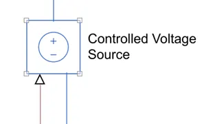
The Controlled Voltage Source block converts a Simulink input signal into an equivalent voltage source. The generated voltage is driven by the input signal of the block.
CONTROLLED CURRENT SOURCE:
The Controlled Current Source block provides a current source controlled by a Simulink signal. The positive current direction is as shown by the arrow in the block icon.
CURRENT SENSOR:
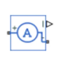
The Current Sensor block represents an ideal current sensor, that is, a device that converts current measured in any electrical branch into a physical signal proportional to the current.
VOLTAGE SENSOR:
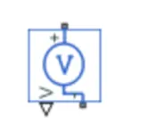
The Voltage Sensor block represents an ideal voltage sensor, that is, a device that converts voltage measured between two points of an electrical circuit into a physical signal proportional to the voltage.
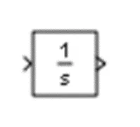
INTEGRATOR:
The Integrator block outputs the value of the integral of its input signal with respect to time.
GIVING THE DRIVE CYCLE:
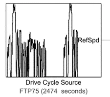
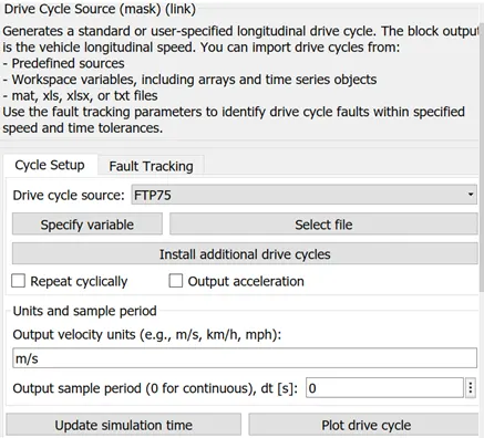
It generates a standard or user-specified longitudinal drive cycle. the block output is the vehicle's longitudinal speed. use the fault tracking parameters to identify drive cycle faults within the specified speed and time tolerances.
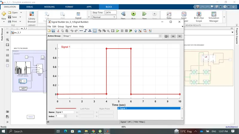
SIGNAL BUILDER BLOCK - IN SIGNAL BUILDER BLOCK IT BASICALLY TAKES THE INPUT IN THE TREMS OF SIGNAL AND WE CAN GET THE OUTPUT AS PER THE DESIRED RESPONSE OBTAINED .
Conclusions and result
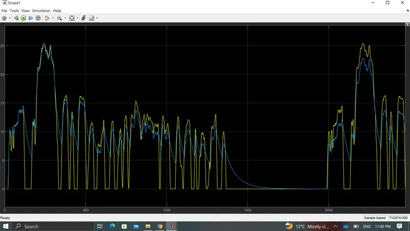
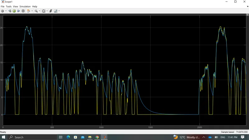
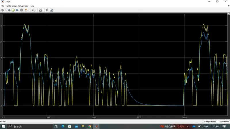
1.as here i have not used ready made driver model so i have designed one PI controller here and upon adjusting the value of P& I and using saturation block .
2. Obtained the value and as per requirement got accelerating and deaccelerating command .
3. So we can say that on changing the different value obtained different values of output.
2.