Project - Speed Control of a Direct Current (DC) motor
Q.1 answer
(i) Mathematical modelling
on applying the kvl
`L(di)/dt+R(i)=V-Kb*w``J(d^2theta)/dt^2+B(d*theta)/dt=Kt*I`
`d(i)/dt =-Ra(I)/La-Kb/La*w+V/La`in the laplace domain i got transfer function as `I(s)=[V(s)-Kb*w]/(s*L+R)`
`w=[Kt*I(s)]/(J*s+B)`
`d(w)/dt =Kt*I/J-B(w)/J`
`Y(t)=w=d(theta)/dt`
now solving for I_dot & w_dot;
`o on solving state space equation for getting the values of matrix A & B1 a
A=[-B/J Kt/J; -Kb/La -Ra/La];
B1=[0 ; 1/La];
% pid controller design for speed control of dc motor parameters
J=0.1; % moment of inertia in kg/m^2
B=0.1 ; %motor viscous friction constant Nms
Kb= 0.01 ;% back emf V/r/s
Kt=0.01 ;% constant for torque Nm?A
Ra=1 ;% armature resistance in ohms
La= 0.5;% inductance of armature in henries
% pid controller gain values
A=[-B/J Kt/J; -Kb/La -Ra/La];
B1=[0 ; 1/La];
% Placement of Poles
fn=1;
wn=2*pi*fn;
zeta=0.95;
p1=-zeta*wn+wn*sqrt(zeta^2-1);
p2=-zeta*wn-wn*sqrt(zeta^2-1);
P=[p1;p2]
K=place(A,B1,P)
fn=1.0;
wn=2*pi*fn;
Kp=142.69
Kd=4.46;
Ki=230;
%% script for plotting the response
%plotting the response
figure(9);
subplot(311);
plot(out.time,out.w,'b--');grid;hold;legend('Ki=230 & zeta=0.95');xlabel('time');ylabel('speed');title('speed plotting');
plot(out.time,out.ref,'m--');
subplot(312);
plot(out.time,out.v,'g--');grid;hold;xlabel('time');ylabel('voltage');
subplot(313)
plot(out.time,out.ia,'k--');grid;xlabel('time');ylabel('armature current')
Conclusion and Result
1.For speed control of dc motor input to the PID controller given as reference input
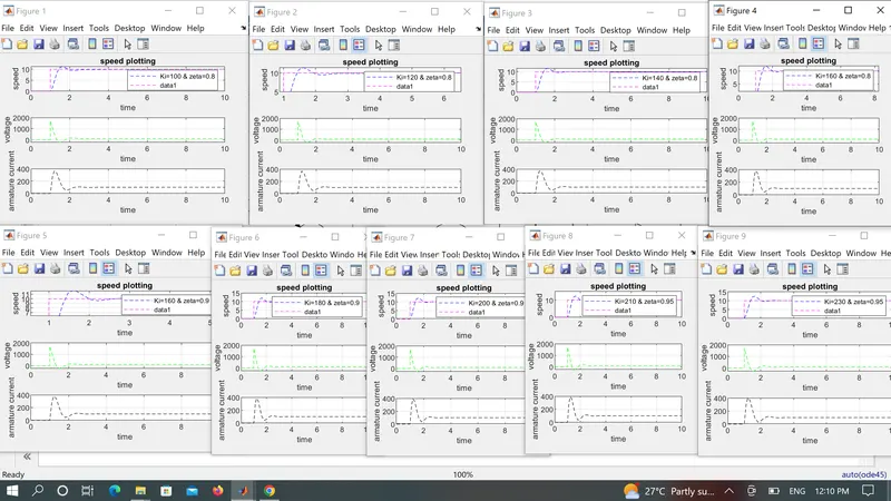
2. After getting the values of different gains from pole placement method so i started tuning or changing the value of Ki .
3.For starting from the value of 100 results were obtained .
3.Objective was to reduce the value of Maximum overshoot ,settling time as well as steady state error.
4.So by constantlt changing the values of Ki i got the waveform linked in answer body for comparison with the reference input or speed.
5.For the value of Ki=230. i got best waveform in that error was very less .
6.Settling time was also good .waveform was settling very clearly.
7.Maximum overshoot was less in comparison for other values as well .
8.If i control all parameters along with settling time and error .got values of Kp,Kd& Ki as
Kp=142.69;
Kd=4.46;
Ki=230;
zeta =0.95;
Comments
on getting for the tuning i have tuned for 9 times for comparative study behavior of dc motor speed control in that for above values i got best tracking possible .In that our output was settling so fast for the values of gain .
Overshoot was also less.
steady state error got very less (as it was very less variation from the refernce speed)
plz find attachment for comparison for different values of Ki and zeta