Project-1: Modelling an electric Car with Li-ion battery
Objective:Create a MATLAB model of electric car which uses lithium ion battery and suitable motor. Choose suitable blocks from Simscape or Powertrain block set. Implement the vehicle speed control using PI controller and generate brake and accelerator commands. Avoid using readymade driver block for speed control.
Prepare a report about your model including following:
Objectives, System level configurations, Model parameters, Results, Conclusion.
ANSWER:
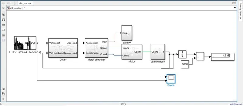
Electric Vehicle:An electric vehicle (EV) is a vehicle that uses one or more electric motors for propulsion . It can be powered by a collector system with electricity from extravehicular sources, or it can be powered autonomously by a battery(sometimes charged by solar panels or by converting fuel to electricity using fuel cell or a generator.
EVs include, but are not limited to, road and rail vehicles surface and underwater vessels, electric craft and electric space craft .
Electric cars function by plugging into a charge point and taking electricity from the grid. They store the electricity in rechargeable batteries that power an electric motor, which turns the wheels. Electric cars accelerate faster than vehicles with traditional fuel engines – so they feel lighter to drive.
DRIVER MODEL: we have implemented the vehicle speed using PID Controller,and generated brake and acceleration command.
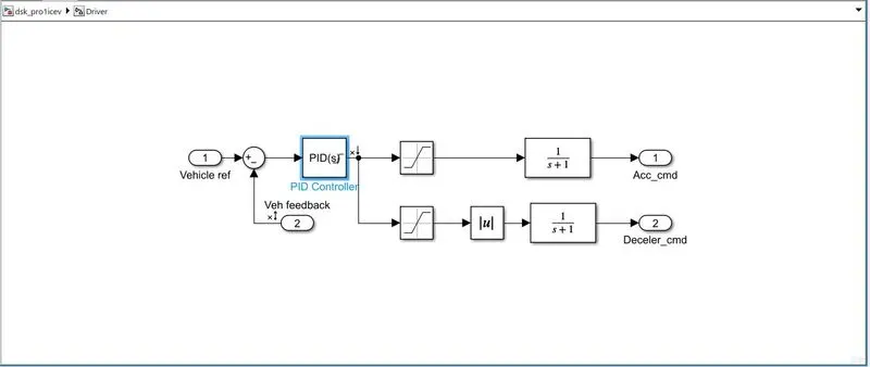
the PI controller is fed from the Drive cycle source as velocity reference and vehicle speed as the feedback both where summed to produce error signal and that is fed to the PI controller two saturation blocks with 1,0 for acceleration command and 0,-1 for brake command as well as the transfer functions for an idealistic plants for non linear compensation so this can produce the accelearation command aand brake command which directly fed to the pwm generator and brake port of the H-bridge
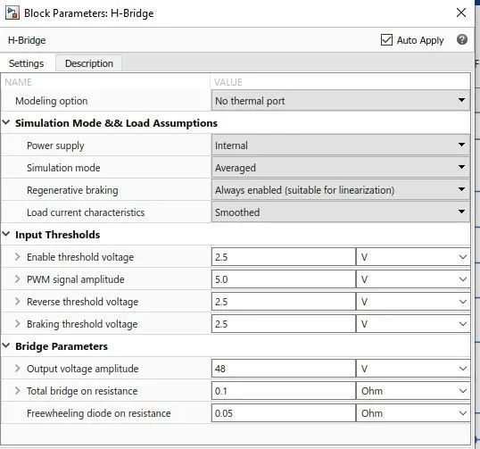
H-BRIDGE AND CONTROLLED PWM VOLTAGE: This block represents an H-bridge motor drive. The block can be driven by the Controlled PWM Voltage block in PWM or Averaged mode. In PWM mode, the motor is powered if the PWM port voltage is above the Enable threshold voltage. In Averaged mode, the PWM port voltage divided by the PWM signal amplitude parameter defines the ratio of the on-time to the PWM period. Using this ratio and assumptions about the load, the block applies an average voltage to the load that achieves the correct average load current. The Simulation mode parameter value must be the same for the Controlled PWM Voltage and H-Bridge blocks.

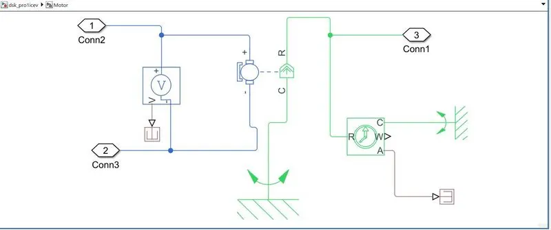
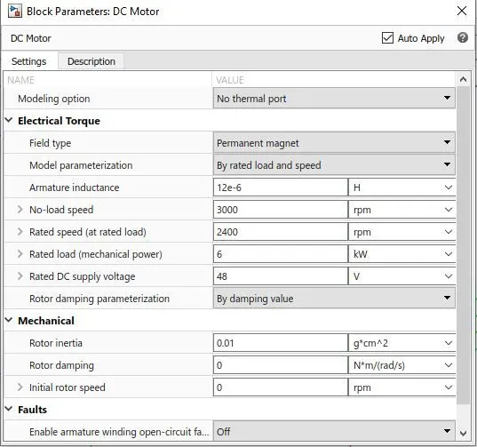
DC MOTOR:
This block represents the electrical and torque characteristics of a DC motor. The block assumes that no electromagnetic energy is lost, and hence the back-emf and torque constants have the same numerical value when in SI units. Motor parameters can either be specified directly or derived from the no-load speed and stall torque. If no information is available on armature inductance, this parameter can be set to some small non-zero value.
When a positive current flows from the electrical + to - ports, a positive torque acts from the mechanical C to R ports. Motor torque direction can be changed by altering the sign of the back-emf or torque constants.
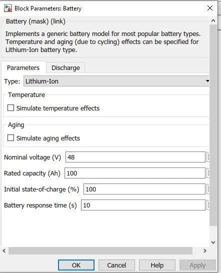
LITHIUM-ION BATTERY:To need power for motor and other equipment we give battery pack. This battery pack is decided from a rating of the motor and considering another electric load. So we used a Lithium battery . 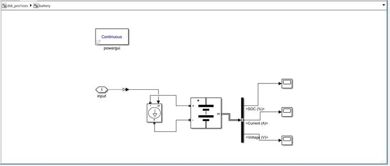
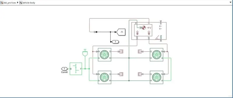
VEHICLE BODY:
Represents a two-axle vehicle body in longitudinal motion. The block accounts for body mass, aerodynamic drag, road incline, and weight distribution between axles due to acceleration and road profile. The vehicle can have the same or a different number of wheels on each axle. Optionally include pitch and suspension dynamics or additional variable mass and inertia.
H is the mechanical translational conserving port associated with the horizontal motion of the vehicle body. The resulting traction motion developed by tires should be connected to this port.
V, NF, and NR are physical signal output ports for vehicle velocity and front and rear normal wheel forces, respectively.
W and beta are physical signal input ports corresponding to headwind speed and road inclination angle, respectively.
A.Tire magic formula:
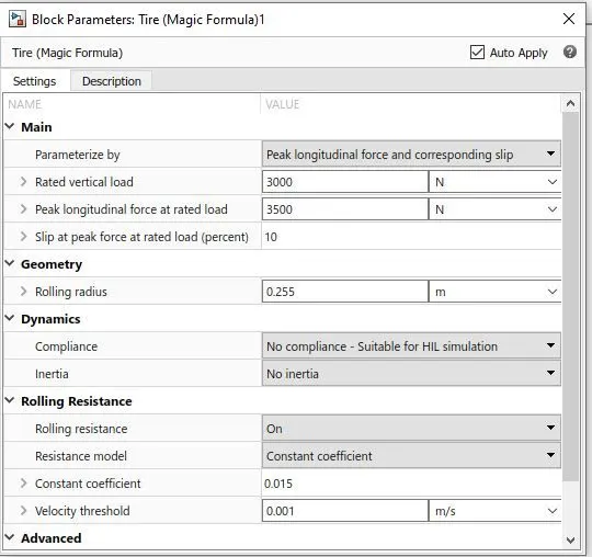
Represents the longitudinal behavior of a highway tire characterized by the tire Magic Formula. The block is built from Tire-Road Interaction (Magic Formula) and Simscape Foundation Library Wheel and Axle blocks. Optionally, the effects of tire inertia, stiffness, and damping can be included.
A is the mechanical rotational conserving port for the wheel axle
H is the mechanical translational conserving port for the wheel hub through which the thrust developed by the tire is applied to the vehicle.
N is a physical signal input port that applies the normal force acting on the tire.
S is a physical signal output port that reports the tire slip. The simple gear will connect to the DC motor.
SIMPLE GEAR:The block represents an ideal, non-planetary, fixed gear ratio gearbox. The gearbox is characterized by its only parameter, Gear ratio, which can be positive or negative. Connections S and O are mechanical rotational conserving ports associated with the box input and output shaft, respectively. The gear ratio is determined as the ratio of the input shaft angular velocity to that of the output shaft. The block generates torque in a positive direction if a positive torque is applied to the input shaft and the ratio is assigned a positive value.
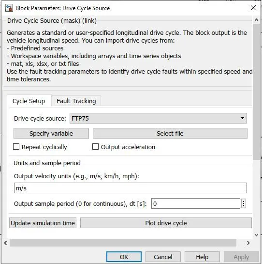
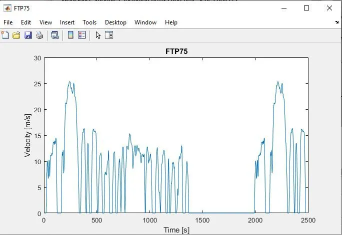
Drive cycle used:Here FTP75 drive cycle is used.
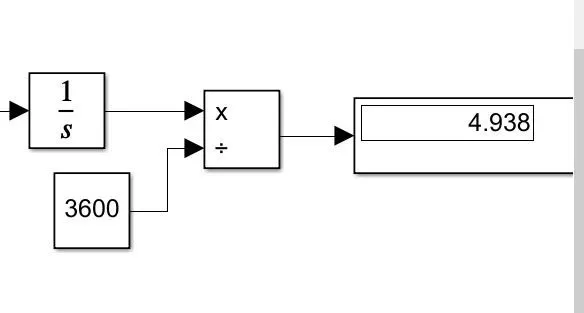
DISTANCE TRAVELLED:
RESULTS:
let us see the simulated results for simulink run time 2474s
Velocity reference and the vehicle vleocity
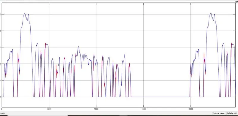
Here we can clearly see that vehicle output is following the input drive cycle.
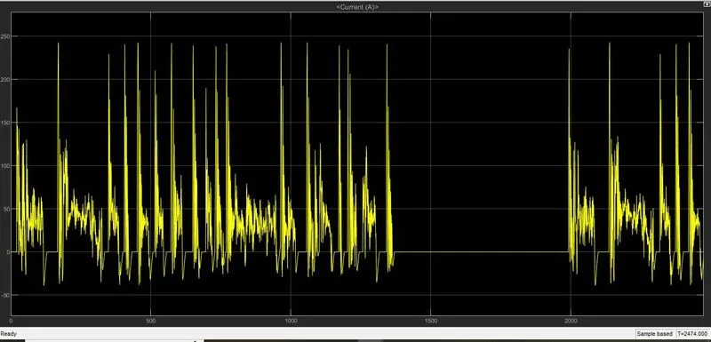
let us see the battery current and soc%
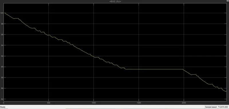
we are seeing the soc % in which it dropped from 100% to neaarly 85% which is meant that battery consumed 15% for the distance of 4.9 kms
Conclusion:An electric car with suitable motor and lithium battery with an PI controller is designed in SIMULINK, and also simulated with standard drive cycle as a velocity reference for PI controller.The vehicle velocity almost synced with the drive cycle input.