Final Project: Design of an Electric Vehicle
Create a MATLAB model of electric car which uses a battery and a DC motor. Choose suitable blocks from Powertrain block set. Prepare a report about your model including following:
Answer:
Before heading towards the modelling lets understand what is eletric vehicle and how it works.:
The vehicles which uses electric motor instead of internal comustio engines ,and battery packs to power these eletric motors are called electric vehicles.These eletric vehicles are also called battery eletric vehicles(BEVs).These eletric vehicles uses an external circuit forcharing batteries,also called electric vehicle supply equipment.
Electric vehicles (EV) enabled by high-efficiency electric motors and controllers and powered by alternative energy sources provide the means for a clean, efficient, and environmentally friendly urban transportation system.Electric vehicles have no emission, having the potential to curb the pollution problem in an efficient way. Consequently, EVs are the only zero-emission vehicles possible.Electric vehicles paved their way into public use as early as the middle of the 19th century, even before the introduction of gasoline-powered vehicles.
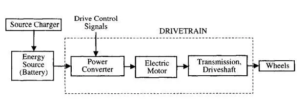
An EV has the following two features:
a. The energy source is portable and chemical or electromechanical in nature.
b. Traction effort is supplied only by an electric motor.
The primary components of an EV system are the motor, controller, power source, and transmission.
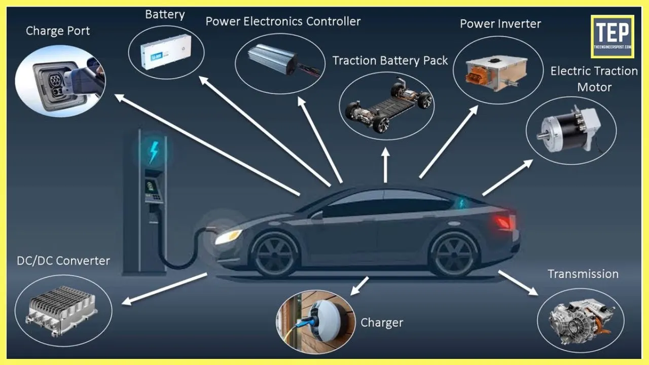
Now we will begin with our eletric vehicle modelling.
Simulation model:
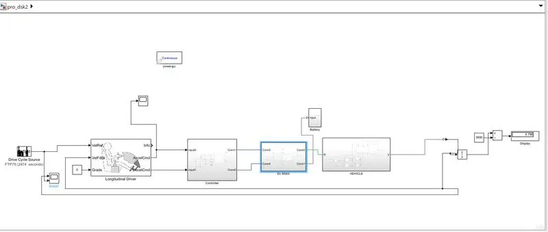
This is the simulation of eletric vehicle which uses dc motor as traction motor and its control circuit.
Objectives:
System level configurations:Following blocks are used in vehicle modelling,
- Drive cycle source
- Longitudinal Driver
- PWM controlled voltage source
- Hbridge
- DC motor
- Vehicle body:it has following components
- tires
- simple gear
- inertia
- battery
- ps to simulink and simulink to converters
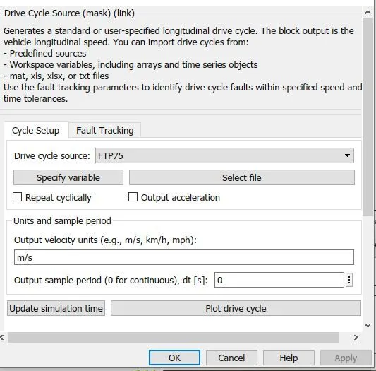
Drive cycle source:A driving cycle is a set of values, generally, velocity vs time, which represents how a vehicle travels through a path. In simple words, it would be a velocity vs time graph of a vehicle.
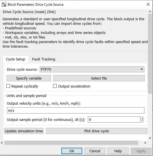
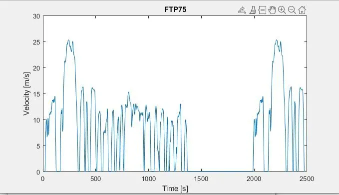
By default there are only two drive cycles available ,we can insert our own drive cycle with the help of spreadsheet data or from workspace.
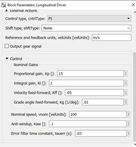
Longitudinal driver:It is quite similar to driver who drives the vehicle.By using reference and feedback velocities this block generates acceleration and braking commands.We use this block to track a drive cycle and to generate the necessary command for drving vehicle.
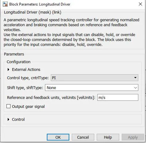
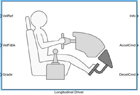
This block consists of following ports/connections:Reference velocity,feedback velocity,grade,acceleration,
deceleration.Input drive cycle is given to reference voltage port ,which is used by this block to create accelerating and braking signals to reduce error between the two velocities by comaparing the feedback velocities.here grade is take as zero since condition of no inclination is taken.
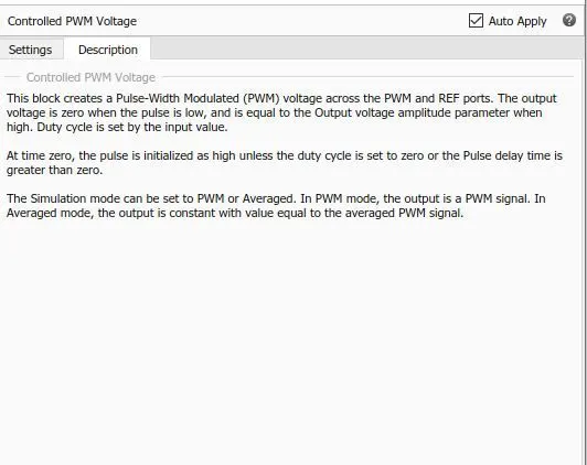
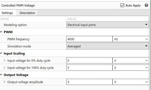
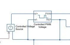
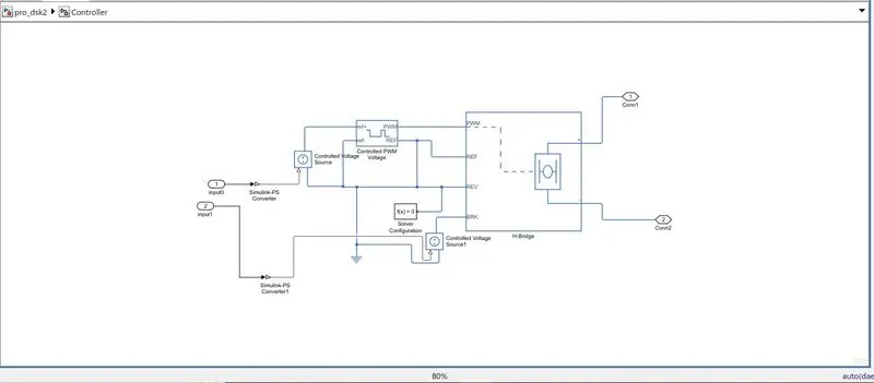
PWM controlled voltage source;This is a built in block available in simulink which provides H-bridge circuit with desired PWM voltage. The output voltage is zero when the pulse is low, and is equal to the Output voltage amplitude parameter when high. Duty cycle is set by the input value.
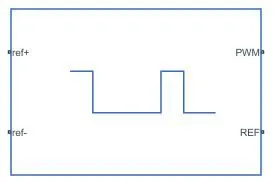
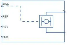
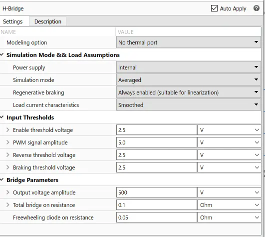
H_BRIDGE:This is part of motor controller,dc motor is driven by H bridge and PWM controlled voltage source.
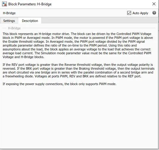
The H-bridge motor drive block is used in the simulink model, which can be driven in PWM or Averaged mode by the Controlled PWM Voltage block.. In Averaged mode, the PWM port voltage divided by the PWM signal amplitude parameter defines the ratio of the on-time to the PWM period.
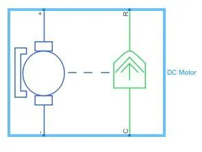
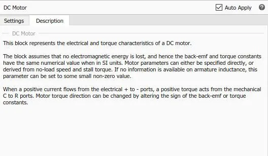
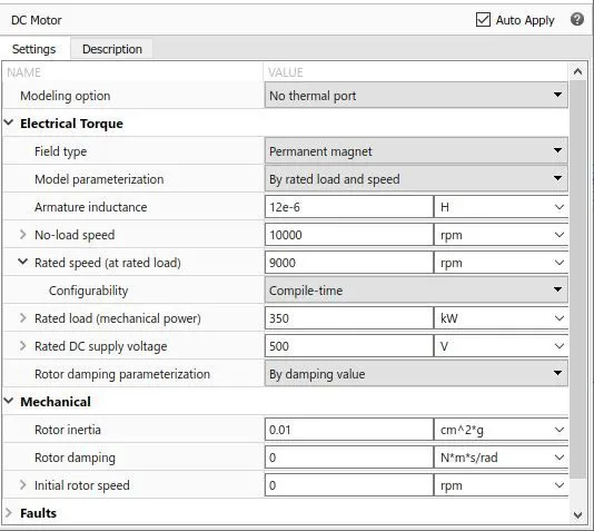
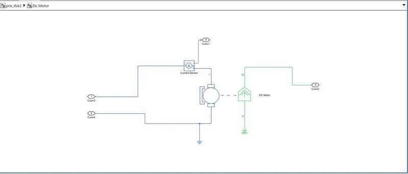
DC MOTOR:The DC Motor block represents the electrical and torque characteristics of a DC motor.It has four connecting ports,positive,negative ,R and C.
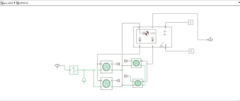
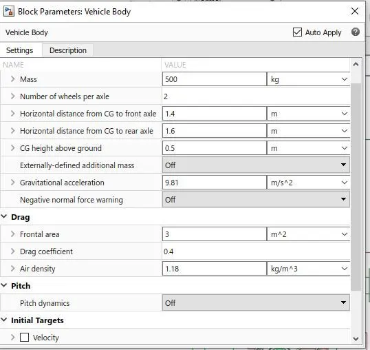
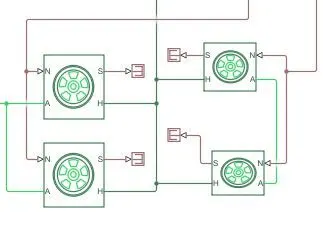
Vehicle Subsystem;Vehicle subsystem consists of vehicle body ,two font tires ,two rear tires,simple gear ,in this block wind and gradient values are kept zero.
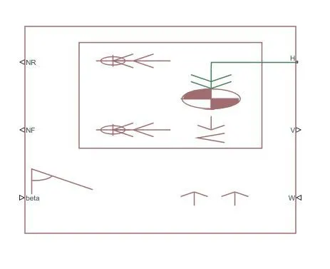
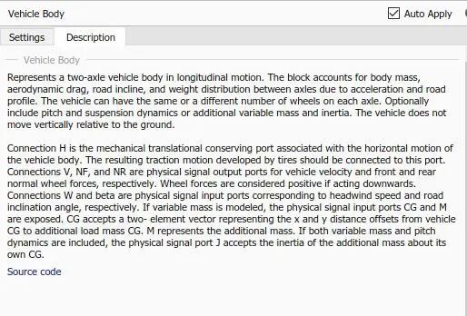
Vehicle body:this block represents the actual body of vehicle ,which includes all parameters like mass,rolling rsistance ,all the forces,gradient,etc.
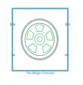
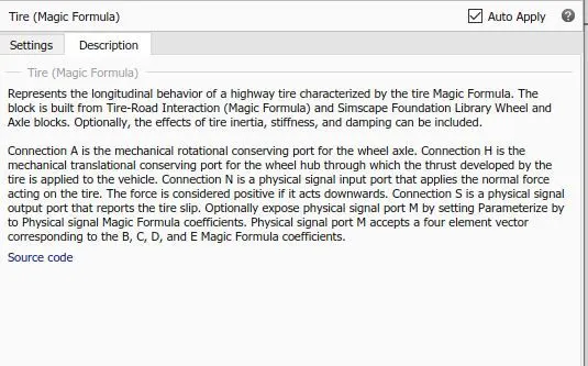
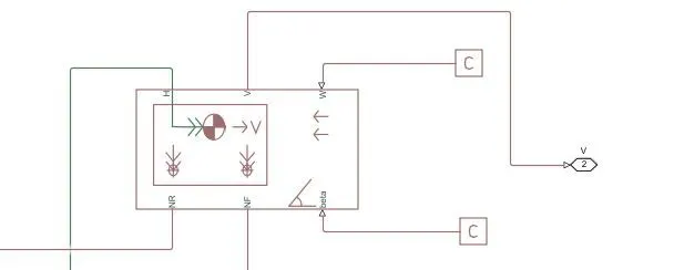
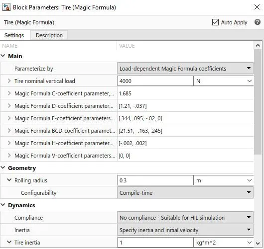
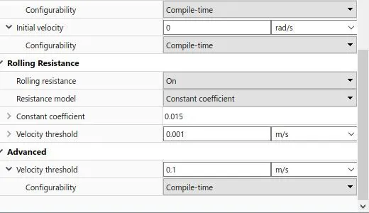
Tires:Tires represents the longitudinal behaviour of a highway tire characterized by tire Magic Formula. It is built from tire road interaction formula . Four wheels are connected to the vehicle body.
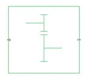
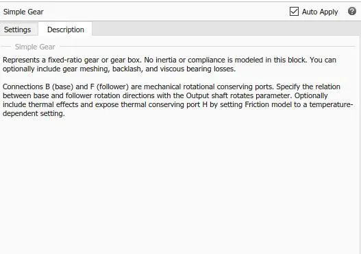
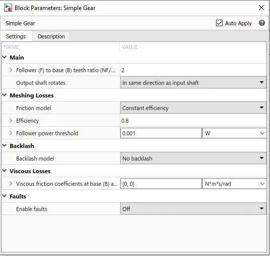
Simple gear:this block represents the fixed ratio gear or gear box.
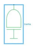
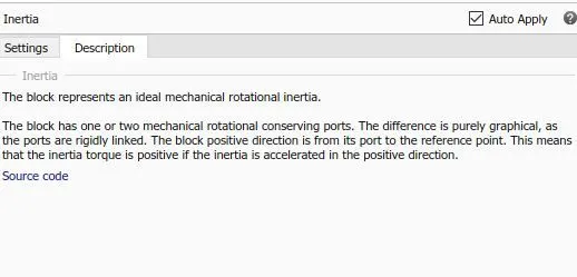
Inertia block:this block represents ideal mechanical rotational inertia.
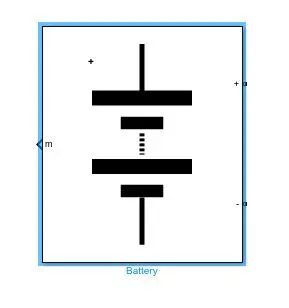
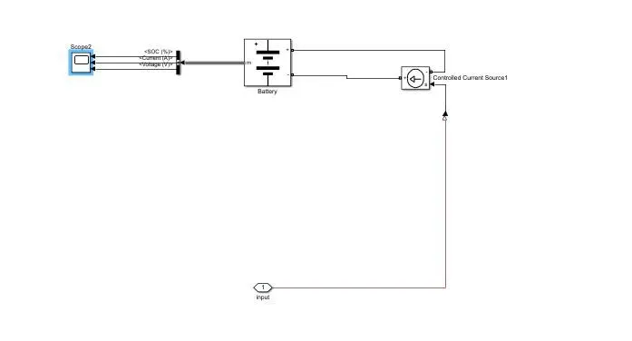
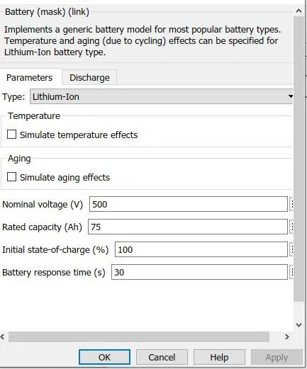
Battery model:this model represents the li-ion battery type.Battery model is selected from Simscape library and current of the motor connected to the controlled current source of battery. The outputs of battery model provides information about voltage, current and SOC.
BLOCK PARAMETERS:
1.Drive cycle:
Longitudinal driver:
CONTROLLED PWM VOLTAGE;
H-bridge:
DC MOTOR:
VEHICLE BODY:
TIRES:
Simple gear:
Battery module:
WORKING AND RESULTS:In thios model input signal or drive cycle data ,FTP75 is provided to the longitudinal driver block.By using PWM controlled voltage block H- bridge switches are turned on and off fo the better control of DC motor.required torque and velocity output is taken from the motor and is supplied as feedback to the driver block.Vehicle speed and ouput velocity can be compared in the scope results.
Drive cycle and vehicle velocity plot:
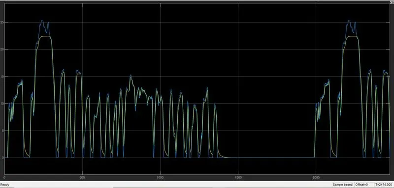
Here we can observe that the actual velocity nearly follows the reference speed(drive cycle).
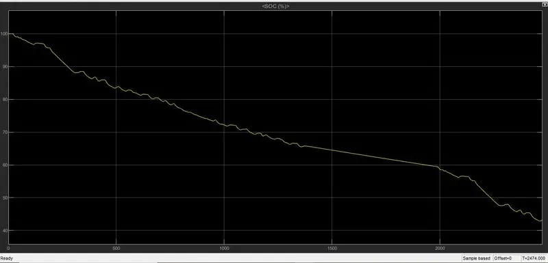
Battery SOC plot:The battery SOC drops to around 39% from the 100% for the given drive cycle.
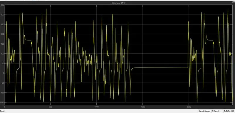
Battery Current:The battery current oscillated between negative and positive values or we can say it reaches to its positive peak value during acceleration and to negative peak during deceleration.
Current during positive peak:330
Current during negative peak:--150A.
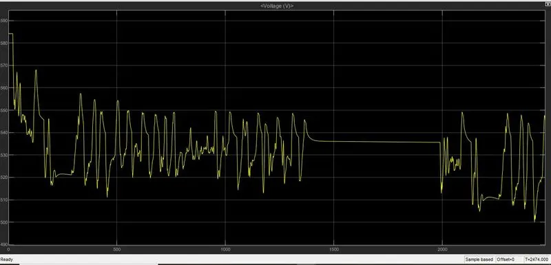
Battery voltage:
Distance travelled by the vehicle for given drive cycle:
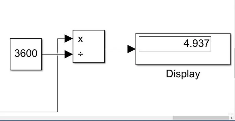
total dictance covered is calculated by integrating the vehicle velocity and divided by time .
The vehicle travelled around 4.9kms for the given drive cycle.
Note : The vehicle was unble to match the input drive cycle, therefore we have manually tuned the motor parameters,pwm and H-bridge paramters to get nearly possible result.
CONSLUSION: By using different simulink blocks like we have modelled our eletric vehicle.we have used FTP75as our drive cycle and we can run our vehicle for different drive cycles,we have observed battery parameters such as its SOC, current and voltage.We have used different forces acting on vehicle to calculate tractive power or propulsion power required.
We can observe that we cannot get exact realtime simulation result,but we can get nearly matching results.