Project - Speed Control of a Direct Current (DC) motor
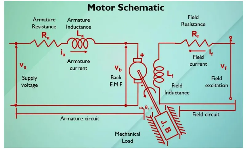
In this project, a Simulink model for the DC motor will be first developed per the schematic shown in Figure 1.
Use the Proportional, Integral, and Derivative (PID) control design knowledge gained in the training to design, develop and test a controller to maintain a desired speed for the motor.
ANSWER:
DC MOTOR:A DC motor or direct current motor is an electrical device/machine which converts electrical energy into mechanical energy.When dc motor is supplied with dc power,a magnetic field is created in its stator ,the field attracts and repels magnets on the rotor,this rotates the rotor.
One of the main reasons why dc motor are preferred over other motors is their ability to precision control their speed ,which is a necessity for inductrial machinery.
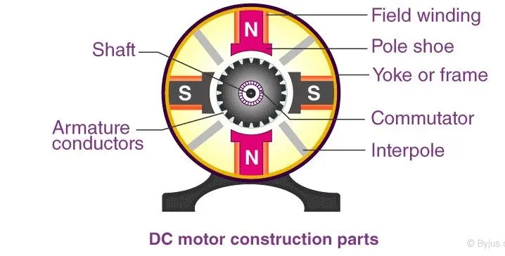
DIFFERENT PARTS OF DC MOTOR:
- ARMATURE/ROTOR
- FIELD COIL OR ROTOR
- COMMUTATOR
- BRUSHES
TYPES OF DC MOTOR:
- Self Excited DC Motor
- Speperately Excited DC Motor
DIAGRAM:
SPEED CONTROL OF DC MOTOR:There are three way to achieve control speed of dc motor:-
- flux control
- voltage control
- armature resitance control
DC Motor Speed control using PID controller:DC motors are used in various industrial applications such as servo motors,speed control applications,for such applications PID controller is usually employed due to its ease of implementation ,ruggedness and easy tuning.
PID Controller:
The term PID stands for proportional integral derivative and it is one kind of device used to control different process variables like pressure, flow, temperature, and speed in industrial applications. In this controller, a control loop feedback device is used to regulate all the process variables.Mathematically PID controller can be defined bt the following equation where e(t) is the error signal with respect to time.Kp,Kd,Ki are the PID constants.
u(t) = Kpe(t)+Ki integral e(t)dt+Kd*de(t)/dt
CIRCUIT DIAGRAM:-
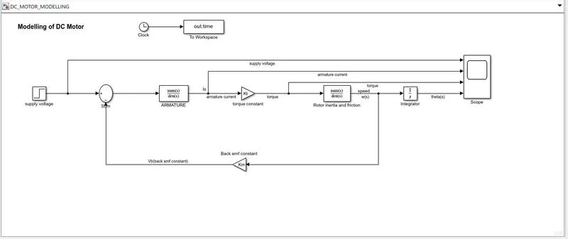
Modelling of DC Motor:
Script File:
% Parameters of dc motor design

J = 0.01; %INERTIA
b = 0.1; %FRICTION
Km = 0.01; %back emf
Kt = 0.01; %torque
Ra = 1; %reistance
La = 0.5; %inductance

%Design of PID controller

A = [-b/J Kt/J;-Km/La -Ra/La];
B = [0;1/La];

%Pole placement
fn = 1;
wn = 2*pi*fn; %natural frequency
zeta = 0.5; %underdamped system

p1 = -zeta*wn+wn*sqrt(zeta^2-1);
p2 = -zeta*wn-wn*sqrt(zeta^2-1);

P = [p1;p2];
K = place(A,B,P);
Kp = 38.3133;
Kd = -2.8584;
Ki = 0;
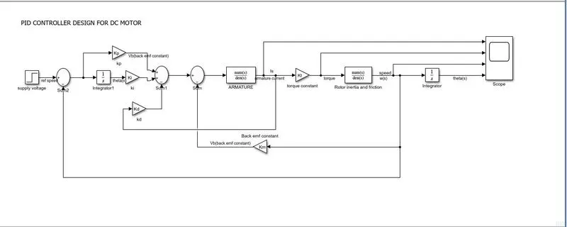
PID Controller Design:
PLOTS/SCOPE RESULT:integral gain values are tuned manually.
CASE 1:Initial Ki value was taken as zero,Kp = 38.3133 and Kd = -2.8584,reference speed = 20
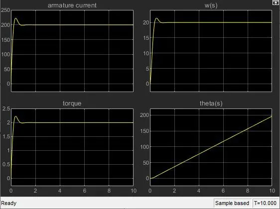
CASE 2:-for Ki = 1,the system is unstable
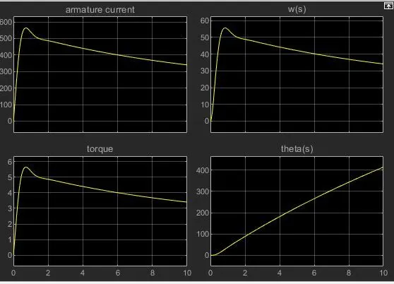
CASE 3:-Now in order to met the control design objectives for settling time ,overshoot and steady state error, values of Kp and Kd values are changed from its original values.
new values: Kp = 30 and Kd = -1 and Ki = 0
BLOCKS USED:Following blocks were used to contruct the simulink model:
CLOCK,CONSTANT,STEP FUNCTION,INTEGRATOR,SUM,SCOPE,GAIN.
CONCLUSION:-For the new values of Kp,Kd and Ki the system is more stable and control design objectives are met for the speed control of dc motor.