Final Project: Electric Rickshaw modelling
OBJECTIVE:Create a detailed MATLAB model of an electric rickshaw (three wheel passenger vehicle) as per details below:
Rear wheels driven by PM brushed type motor
Assume efficiency points of motor controller and motor
Make an excel sheet of all input and assumed data
Results: For any three standard driving cycles show energy consumption, temperature rise of motor and controller for 100 km constant speed driving at 45 kmph.
(Note- The simulink model file should be compulsorily attached)
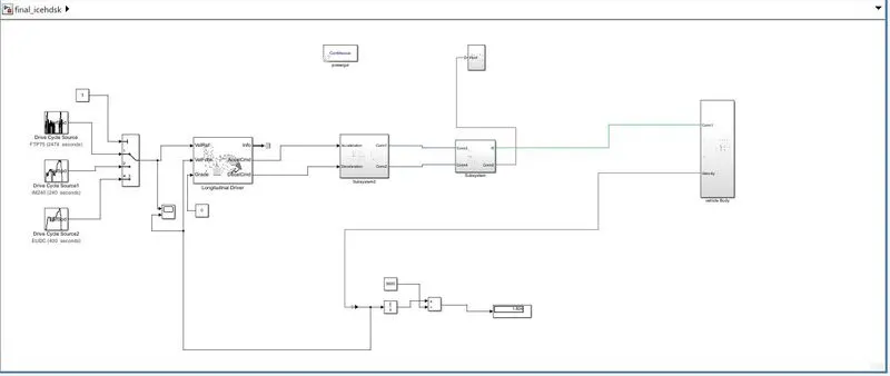
VEHICLE MODEL: Electric rikshaw model is attached below.
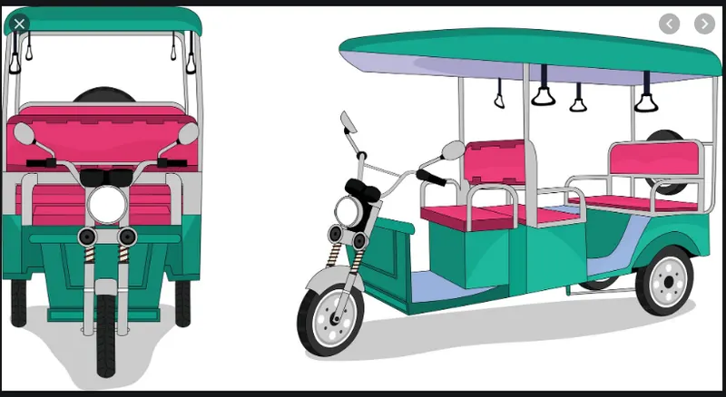
In this project, we going to build the MATLAB model of the ELECTRIC RICKHAEW by using a PM brushed type DC motor and a suitable Lithium-Ion battery for the motor. Auto rickshaws are three wheeled vehicle that are
extensively used in many Asian countries as taxis for the people and goods. These three wheeled vehicles play the most important role as public, private and para-transit modes of transportation and they are suited to the Indian traffic environment.
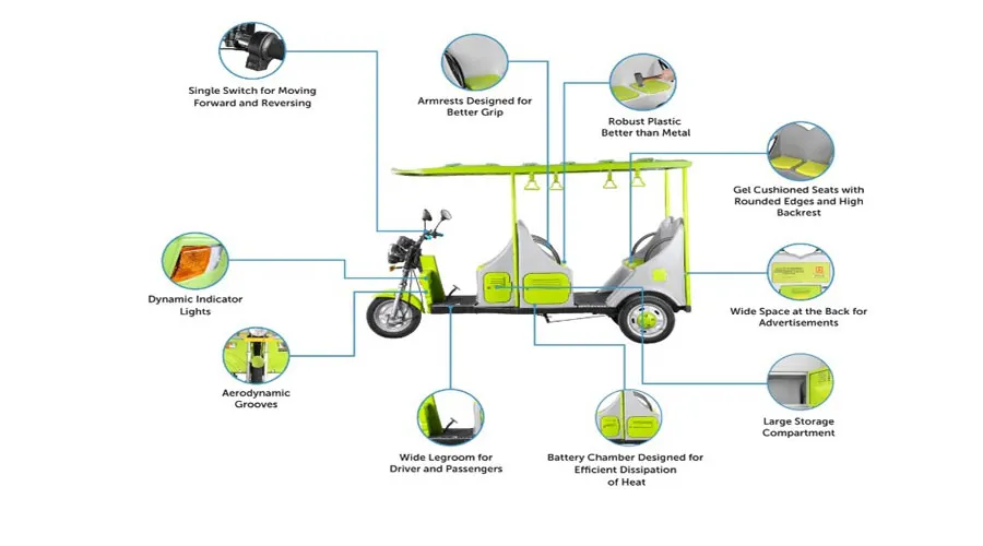
The Main Components Of E Rickshaws:The bodyweight of the E- rickshaw is extremely light and the lithium-ion batteries have a good tenure. The vehicle uses the best quality metal and fiberglass such that every passenger experiences a comfortable ride. The main elements that actually drive the electric rickshaw are a motor, controller, harness, and throttle.
The best part of this rickshaw is that they need minimal maintenance which is not only cost-effective but also requires less effort.
The 3 wheeler E- rickshaw is definitely the best substitute for fuel driven vehicles and efficient when comes to battery power. Also, there is no emission of harmful pollutants from this vehicle so it helps to increase the durability and strengthens the vehicle. The materials which are used in constructing the vehicle such as fibreglass help it to make the vehicle more efficient. Also, this vehicle is absolutely perfect to cover the short distance as well as carry small loads.
How does the Vehicle Work?
The body weight of the E- rickshaw is extremely light and because of that durability of the battery does not get decreased. The main elements that actually drive the electric rickshaw are a motor, controller, harness and most importantly its throttle. To get the best service and to increase the benefits from this vehicle these elements are essential.
Development of e-rickshaw in India:E-Rickshaw's have now transitioned from being a market entrant in the automobile segment of the country to evolve as a leading short-distance transport solution. This segment has gained spurt in the last three years and the growth has been phenomenal. Although, this segment is dominated by a host of unorganized players the established names have also identified the growth beacon and are expected to foray into the segment. One of the first attempts to design electric rickshaws was done by Nimbkar Agricultural Research Institute in the late 1990s.In India, this so-called e-rickshaws are widely spread all over the country, starting to gain popularity around 2011. The design is now much different from cycle rickshaws. Today, e-rickshaws play a vital role in providing livelihood to people in India. Due to their low cost and high efficiency, they are accepted on the Indian streets, but government policies have been threatening the e-rickshaw and banned its use in the capital city Delhi but failed to put them off the streets. E-rickshaws are still rising in number and widely used in Delhi and other parts of India. In Delhi, as per government official's figures in April 2012, their number was over 100,000.
LONGITUDINAL DRIVER BLOCK:
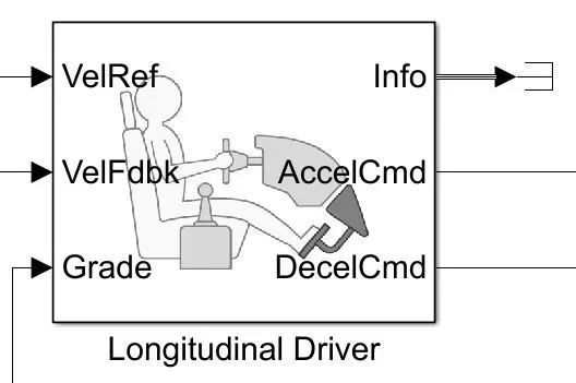
The Longitudinal Driver block implements a longitudinal speed-tracking controller. Based on reference and feedback velocities, the block generates normalized acceleration and braking commands that can vary from 0 through 1. You can use the block to model the dynamic response of a driver or to generate the commands necessary to track a longitudinal drive cycle.
DRIVE CYCLE SOURCE:
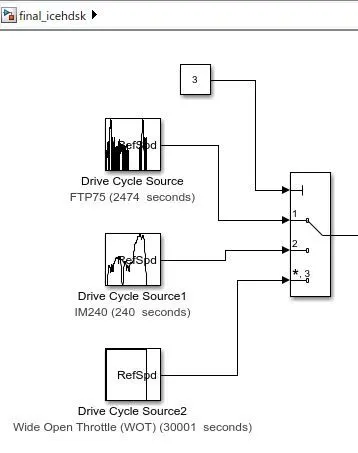
As shwon above thre different drive cycles are given as input to the longitudinal driver through multiport switch.
H-BRIDGE AND CONTROLLED PWM VOLTAGE:
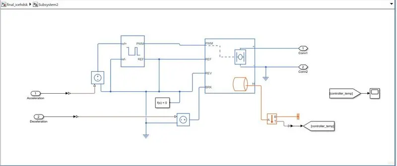
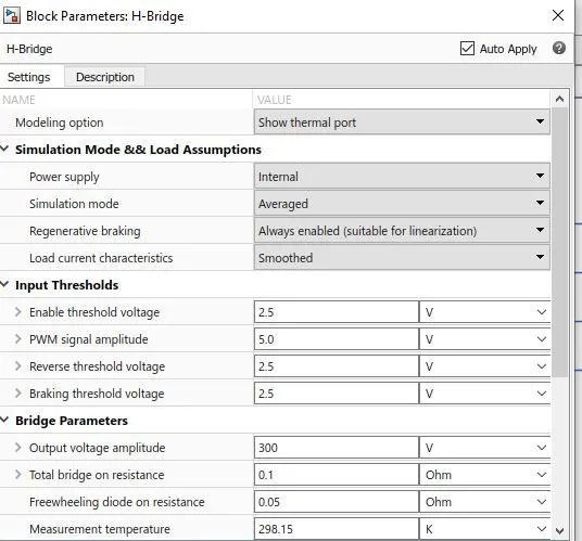
This block represents an H-bridge motor drive. The block can be driven by the Controlled PWM Voltage block in PWM or Averaged mode. In PWM mode, the motor is powered if the PWM port voltage is above the Enable threshold voltage. In Averaged mode, the PWM port voltage divided by the PWM signal amplitude parameter defines the ratio of the on-time to the PWM period. Using this ratio and assumptions about the load, the block applies an average voltage to the load that achieves the correct average load current. The Simulation mode parameter value must be the same for the Controlled PWM Voltage and H-Bridge blocks.
DC MOTOR:
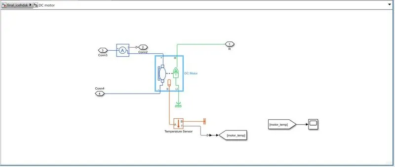
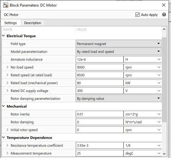
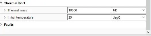
This block represents the electrical and torque characteristics of a DC motor. The block assumes that no electromagnetic energy is lost, and hence the back-emf and torque constants have the same numerical value when in SI units. Motor parameters can either be specified directly or derived from the no-load speed and stall torque. If no information is available on armature inductance, this parameter can be set to some small non-zero value.
When a positive current flows from the electrical + to - ports, a positive torque acts from the mechanical C to R ports. Motor torque direction can be changed by altering the sign of the back-emf or torque constants.
The battery input is given through the motor drive controller.
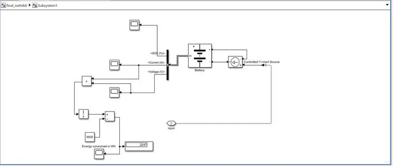
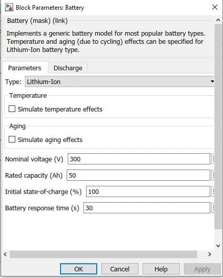
LITHIUM-ION BATTERY:To need power for motor and other equipment we give battery pack. This battery pack is decided from a rating of the motor and considering another electric load. So we used a Lithium battery .
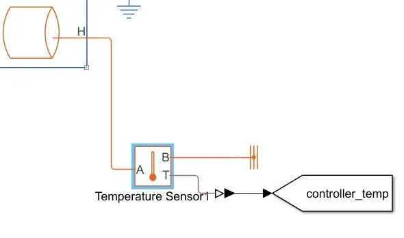
TEMPERATURE SENSOR: USED FOR THE MEASUREMENT OF MOTORAND CONTROLLER TEMPERATURE.
VEHICLE BODY:
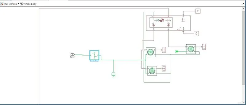
Represents a two-axle vehicle body in longitudinal motion. The block accounts for body mass, aerodynamic drag, road incline, and weight distribution between axles due to acceleration and road profile. The vehicle can have the same or a different number of wheels on each axle. Optionally include pitch and suspension dynamics or additional variable mass and inertia.
H is the mechanical translational conserving port associated with the horizontal motion of the vehicle body. The resulting traction motion developed by tires should be connected to this port.
V, NF, and NR are physical signal output ports for vehicle velocity and front and rear normal wheel forces, respectively.
W and beta are physical signal input ports corresponding to headwind speed and road inclination angle, respectively.
A.Tire magic formula:
Represents the longitudinal behavior of a highway tire characterized by the tire Magic Formula. The block is built from Tire-Road Interaction (Magic Formula) and Simscape Foundation Library Wheel and Axle blocks. Optionally, the effects of tire inertia, stiffness, and damping can be included.
A is the mechanical rotational conserving port for the wheel axle
H is the mechanical translational conserving port for the wheel hub through which the thrust developed by the tire is applied to the vehicle.
N is a physical signal input port that applies the normal force acting on the tire.
S is a physical signal output port that reports the tire slip.
The auto-rickshaw consists of 3 Wheels (1 Front & 2 rear).
The simple gear will connect to the DC motor.
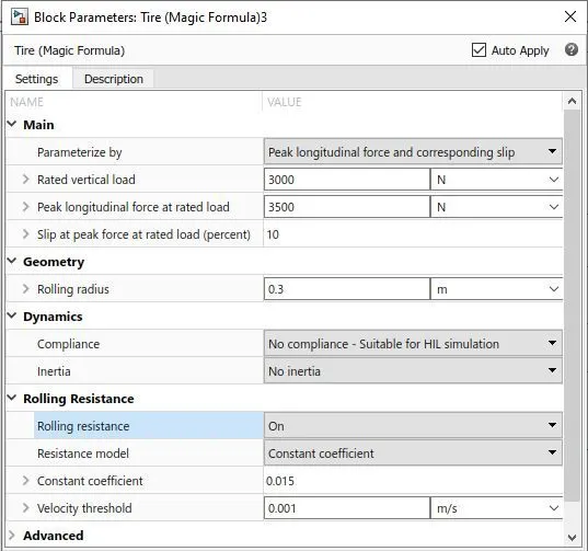
Tire parameters:
SIMPLE GEAR:
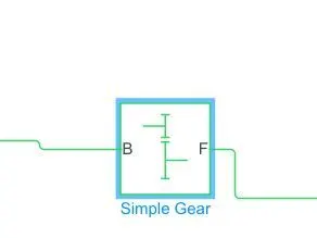
The block represents an ideal, non-planetary, fixed gear ratio gearbox. The gearbox is characterized by its only parameter, Gear ratio, which can be positive or negative. Connections S and O are mechanical rotational conserving ports associated with the box input and output shaft, respectively. The gear ratio is determined as the ratio of the input shaft angular velocity to that of the output shaft. The block generates torque in a positive direction if a positive torque is applied to the input shaft and the ratio is assigned a positive value.
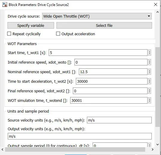
RESULTS: We have used three drive cycles,FTP75(2474SECONDS),IM240 AND WOT (30001 SECONDS).
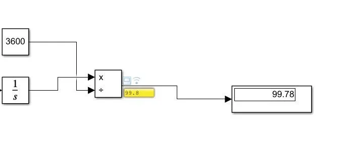
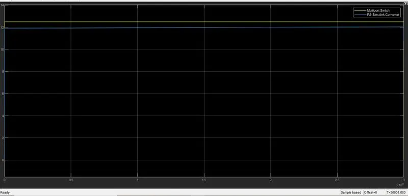
1.Wide Open Trottle(WOT): Vehicle covered total distance of 99.78 kms at constant spedd of 45Kmph.
DISTANCE COVERED:
PLOT:
Battery SOC:
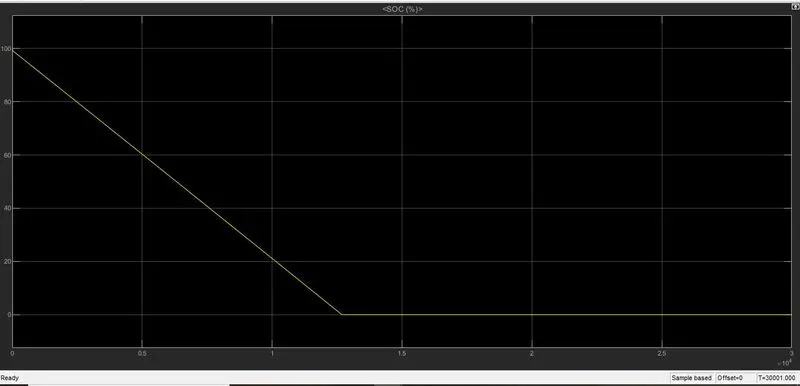
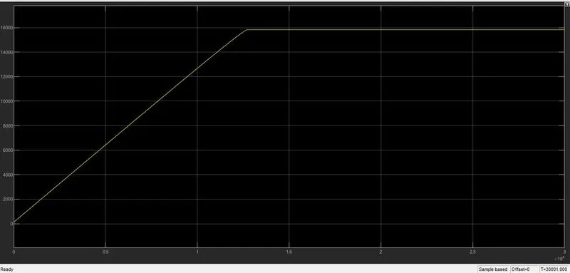
ENERGY consumption:total energy consumed = 15830 Wh
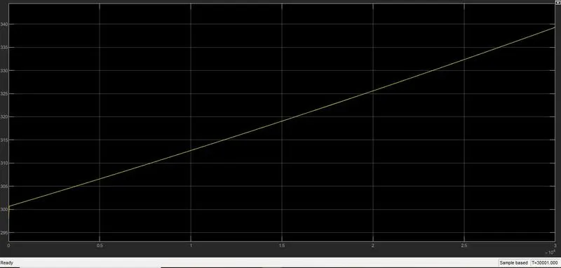
Heat generated by motor:339k
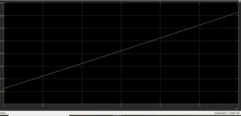
Heat generated by motor controller:361k
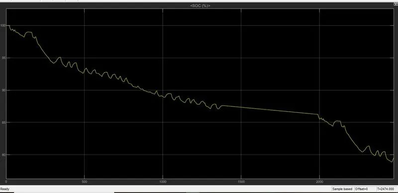
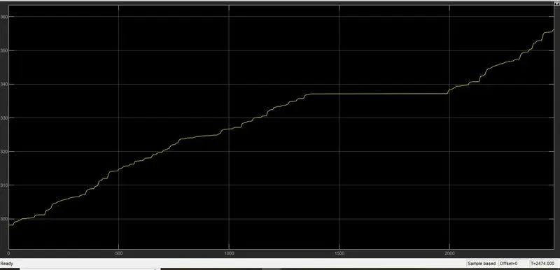
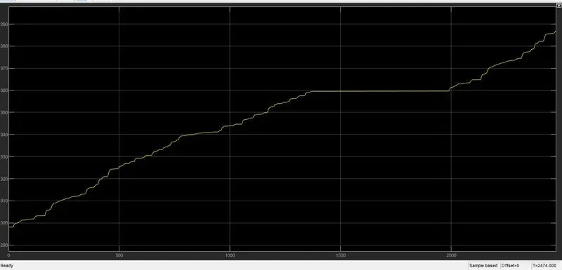
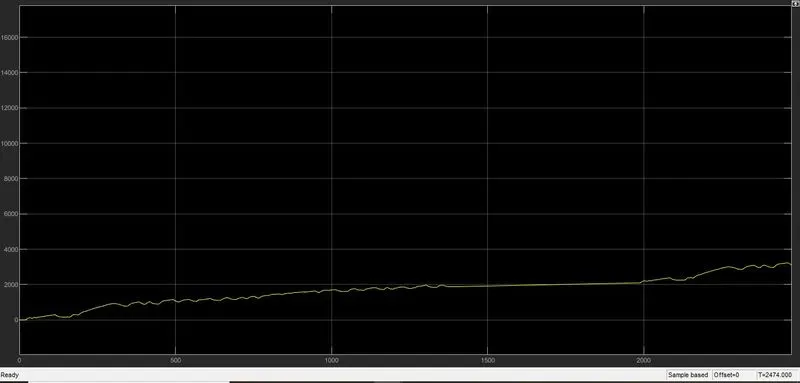
2.FTP75 DRIVE CYCLE: simulation time =2474 seconds.
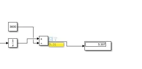
DISTANCE COVERED:It covered 5.3km
PLOT:
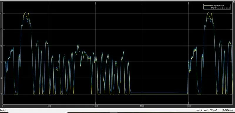
BATTERY SOC:100% to 79%
Heat generated by motor:355k
Heat generated by motor controller:385k
ENERGY CONSUMED DURING THIS DRIVE CYCLE:3124Wh
3.NEDC drive cyclE (1180SECONDS):
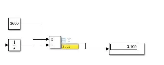
DISTANCE COVERED: ALMOST COVERED 3.1km
PLOT:
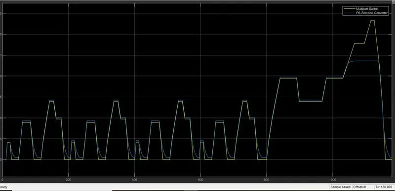
Battery SOC:
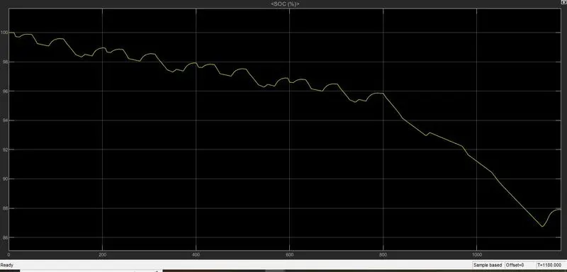
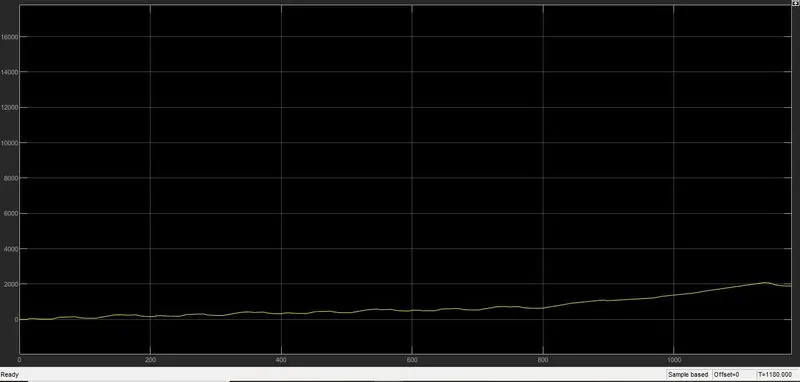
ENERGY CONSUMED DURING THIS DRIVE CYCLE:1895Wh
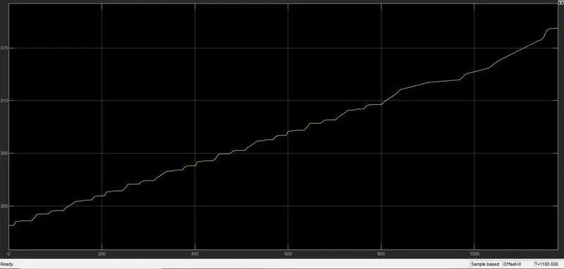
Heat generated by motor:317K
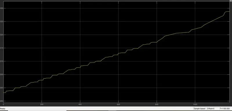
Heat generated by motor controller:328.5K
CONCLUSION:The calculated power required by the motor is around 1.3Kw.
During vehicle simulation it was aobserved that for given reference drive cycle the calculated motor power is not sufficient or meet oue requirements.So,few parameters like motor mechanical power,rated speed and no load speed are manually tuned to meet our design requirments.