Project-1: Modelling an electric Car with Li-ion battery
AIM
To Create a MATLAB model of electric car which uses lithium ion battery and suitable motor. Choose suitable blocks from Simscape or Powertrain block set. Implement the vehicle speed control using PI controller and generate brake and accelerator commands. Avoid using readymade driver block for speed control.
Prepare a report about your model including following:
OBJECTIVES
System level configurations, Model parameters, Results, Conclusion.
PROCEDURE
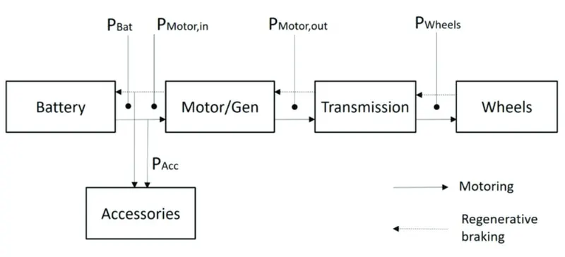
Flowchart of design of electric vehicle
-
Predict the engine torque and fuel consumption that a vehicle requires to achieve desired speed and acceleration for a given gear shift reference.
-
Produce realistic velocity and shift references for closed loop acceleration and braking commands for vehicle control and plant models.
-
Study, tune, and optimize vehicle control, system performance, and system robustness over multiple drive cycles
LONGITUDINAL DRIVER
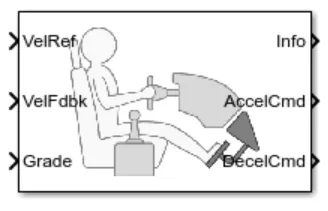
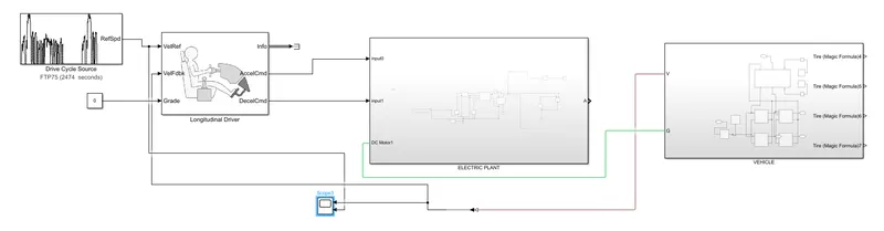
The Longitudinal Driver block implements a longitudinal speed-tracking controller. Based on reference and feedback velocities, the block generates normalized acceleration and braking commands that can vary from 0 through 1. You can use the block to model the dynamic response of a driver or to generate the commands necessary to track a longitudinal drive cycle.
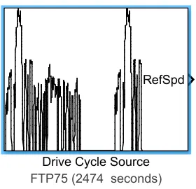
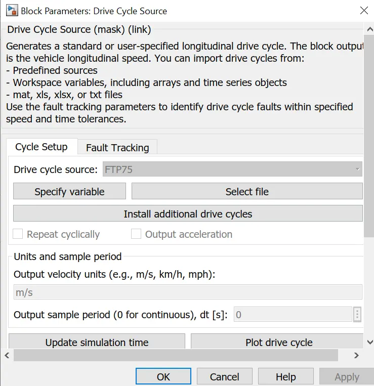
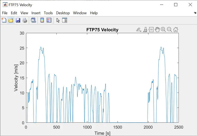
Here the the vehiclereference(input velocity port) is connected to the drivecycle.
vehiclefeedback(outputs velocity data) is connected to the vehiclebody.
Grade(angle of inclination port) is connected with a zero constant input.
info port is for the bus signals which consists of block calculations
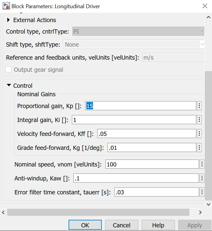
The control type here is PI controller
The acceleration and deceleration are connected the control voltage source which is the input of the electricplant.if the reference velocity is greater than feedback velocity an acceleration command will be given as an output to the controlled voltage source.if the reference velocity is less than feedback velocity then deceleration coomand is given as output to the controlled voltage source.
2 ELECTRIC PLANT SUBSYSTEM
Here the subsystem consists of the main electrical connections.
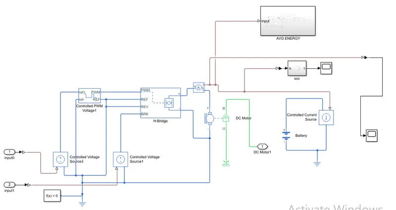
The outputs from the acceleration(1) and decelerayion(2) are connected to a simulink physical signal converter which converts the input velocity data to the input to the physical signals such as voltage to the controlled voltage source.
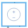
The Controlled Voltage Source block converts a Simulink input signal into an equivalent voltage source. The block represents an ideal voltage source that is powerful enough to maintain the specified voltage at its output regardless of the current passing through it. The output voltage is V = Vs, where Vs is the numerical value presented at the physical signal port.
.The one output from the first controlled voltage source is connected to the reference port of controlled pulsewidth modulation voltage.
CONTROLLED PWM VOLTAGE
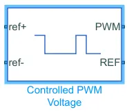
The Controlled PWM Voltage block represents a pulse-width modulated (PWM) voltage source. The block has two modeling variants, accessible by right-clicking the block in your block diagram and then selecting the appropriate option from the context menu
-
Electrical input ports — The block calculates the duty cycle based on the reference voltage across its ref+ and ref- ports. This modeling variant is the default.
-
PS input — Specify the duty cycle value directly by using an input physical signal port.
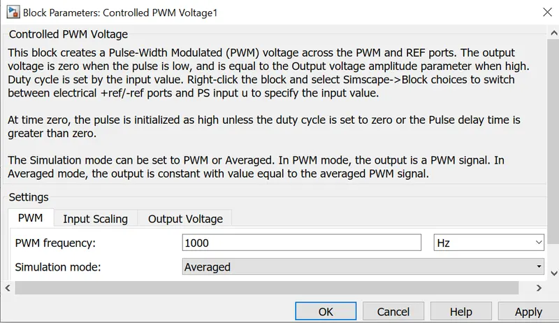
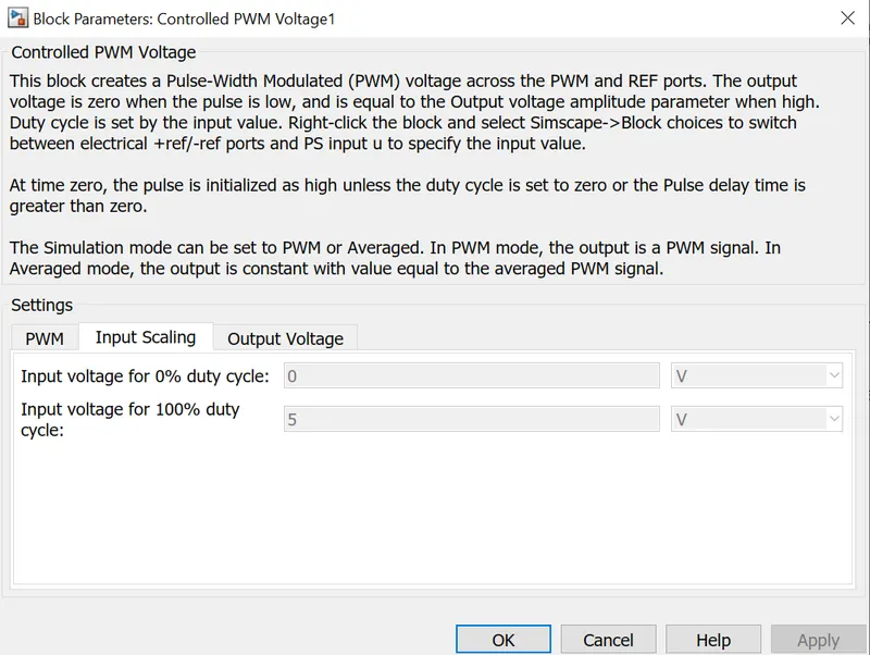
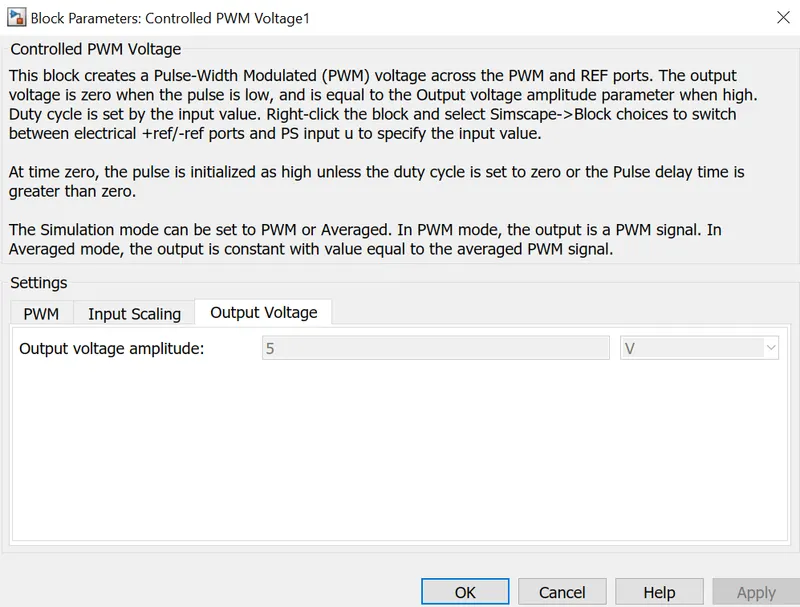
I have used the controlled pwm voltage in rorder to give controlled pulse width modulation to the H bridge.The pwm and reference ports output of the controlled PWM voltage are connected input ports such as PWM and reference of H bridge respectively.if the pulse is low the outputvoltage is considered as V where as if the pulse is high the output voltage will be equal to the output voltage amplitude whic is 240V in the H bridge block the pulses of voltage created by this block are dependent on the duty cycle.The duty cycle is set by the input of the controlled PWM voltage block.
H BRIDGE
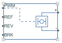
The H-Bridge block represents an H-bridge motor driver. The block has the following two Simulation mode options:The H-Bridge block output is a controlled voltage that depends on the input signal at the PWMport. If the input signal has a value greater than the Enable threshold voltage parameter value, the H-Bridge block output is on and has a value equal to the value of the Output voltage amplitude parameter. If it has a value less than the Enable threshold voltage parameter value, the block maintains the load circuit using the freewheeling mode.
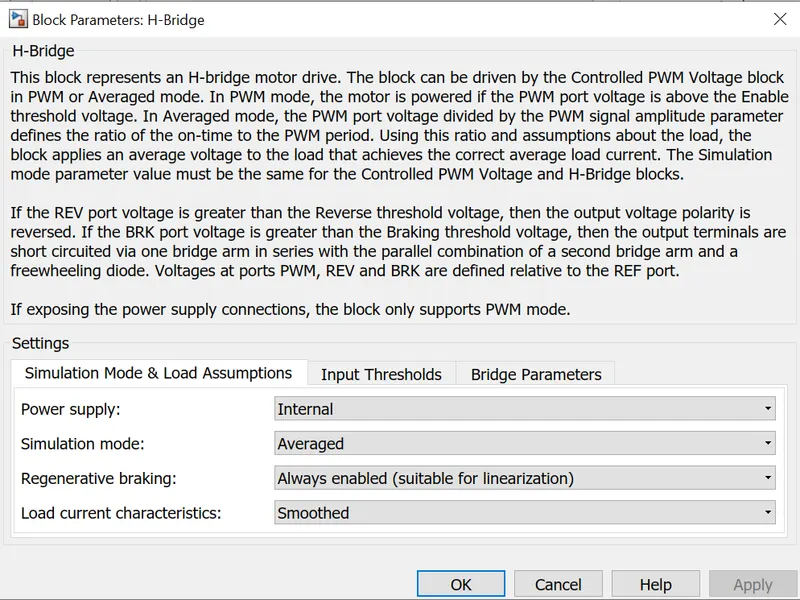
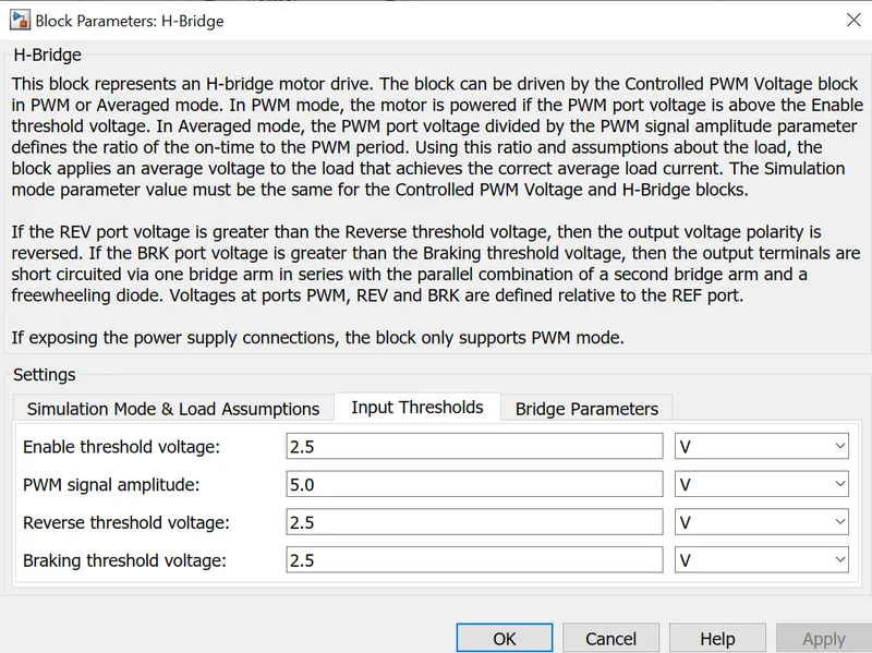
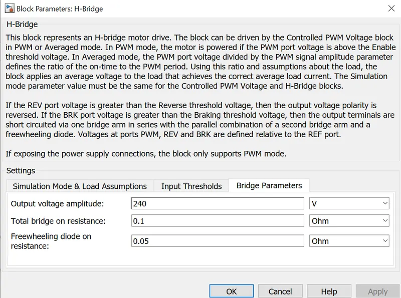
I have chosen H bridge as the power converter which converts the correct form and magnitude of the dc voltage from the battery to the motor.The H bridge has two sides. one is the left side which is controlling of the voltage signal and the other one is the controlled voltage output.
PWM nd REF are connected from the controlled pwm Voltage ports of PWM nd REF respectively.
REV(reverse port) which is connected to the negative reference of the controlle pwm voltage and controlle voltage source.
BRK(brake) which connects the output of the second controlled voltage source
DC MOTOR
Here is the core machine of an electric vehicle which converts the electrical energy to mechanical energy.
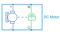
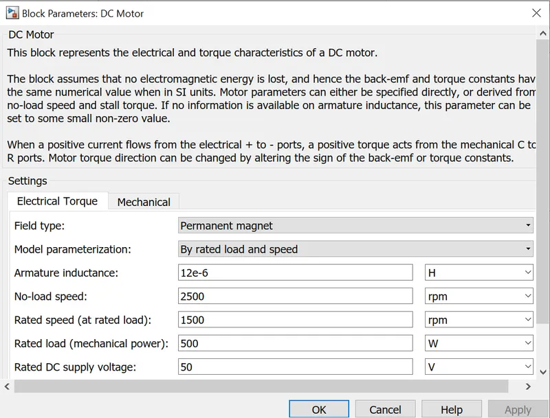
This block represents a dc block with specific torque and speed characteristics .voltage is the input port. it has a mechanical rotational conserving port as output.here we use permanent magnet type dc motor with with 10000 rpm speed at no load,8000 rpm rated speed,75KW rated load.the mechanical side is on the right side and the electrical is on the left side,here C refers to the casing and R refers to the rotation of the motor which produces torque.The elecrical part conmsist of a positive and negative terminals.if the positive of battery is connected to positive of dc motor and negative simulatanously then a positive torque is produced from C to R.The direction of the torque can be changed by changing the sign of back emf to the torque constant.since the cport is stationary it need to connect to a mechanical rotational reference.The R block is connected to a simple gear block in the vehicle body block.The posotive side of the electrical side is connected with the positive terminal of the H bridge.
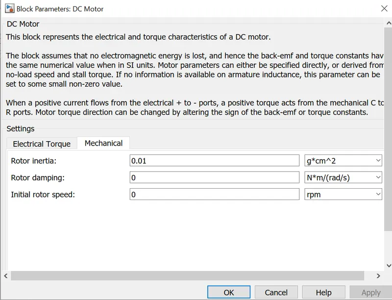
The values of supply voltage,rated voltage and other parametres are changed in the block parameters which are shown below
ENERGY SUBSYSTEM
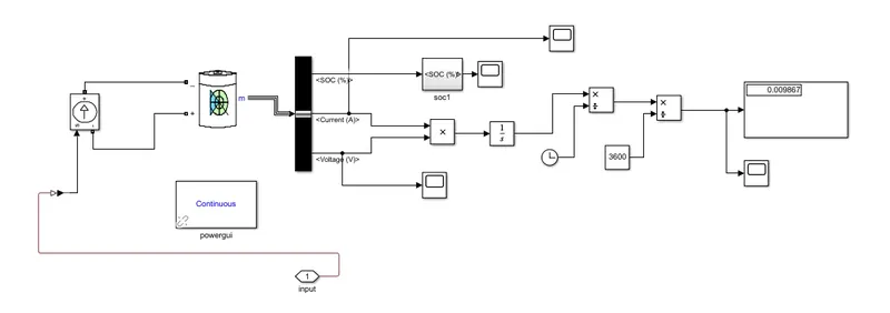
Energy calculation subsystem is created to give the power from a lithium ion battery and calculate the parameters
Lithium Ion Battery
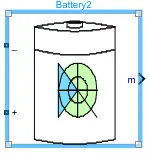
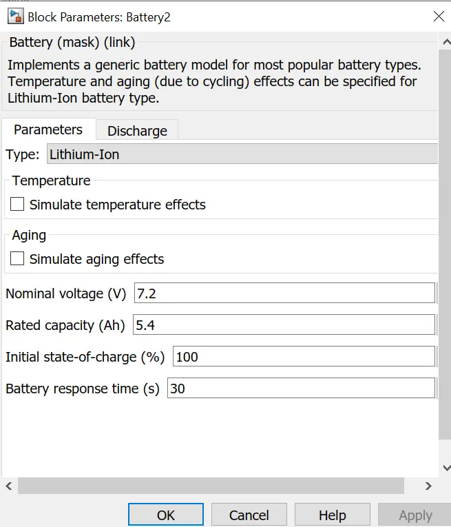
A lithium-ion (Li-ion) battery is an advanced battery technology that uses lithium ions as a key component of its electrochemistry. During a discharge cycle, lithium atoms in the anode are ionized and separated from their electrons. The lithium ions move from the anode and pass through the electrolyte until they reach the cathode, where they recombine with their electrons and electrically neutralize. The lithium ions are small enough to be able to move through a micro-permeable separator between the anode and cathode. In part because of lithium’s small size (third only to hydrogen and helium), Li-ion batteries are capable of having a very high voltage and charge storage per unit mass and unit volume.
Li-ion batteries can use a number of different materials as electrodes. The most common combination is that of lithium cobalt oxide (cathode) and graphite (anode), which is most commonly found in portable electronic devices such as cellphones and laptops. Other cathode materials include lithium manganese oxide (used in hybrid electric and electric automobiles) and lithium iron phosphate. Li-ion batteries typically use ether (a class of organic compounds) as an electrolyte
Lithium ion battery is connected from the ammeter via controlled current source and is connected to a bus selector to find out the state of charge and average energy consumption.
BATTERY

The battery is connected to the power source of the model taht power is generated and transmitted via a current a controlled current source
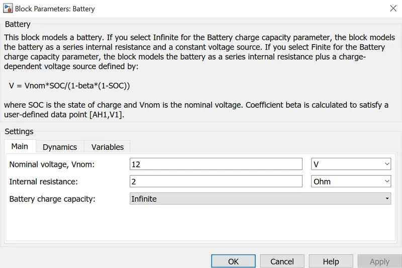
CONTROLLED CURRENT SOURCE
The controlled current source controls the amount of the current flows.The output from the controled current source (output of battery) is connected via a current sensor to the dc motor and H bridge.
CURRENT SENSOR
Its used for measuring the amount of current that flows.A SOC is connected with it inorder to check the amount of charge left in the battery.
SOC CALCULATION SUBSYSTEM
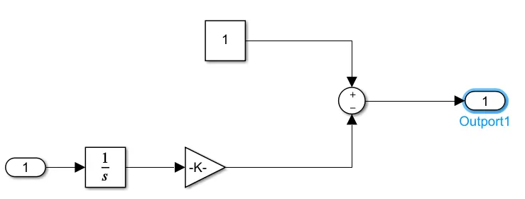
Gain and Integrator are connected in series to the negative port of the sum and a constant to the positive side of operator.The output of the sum is connected to the scope.
Tire
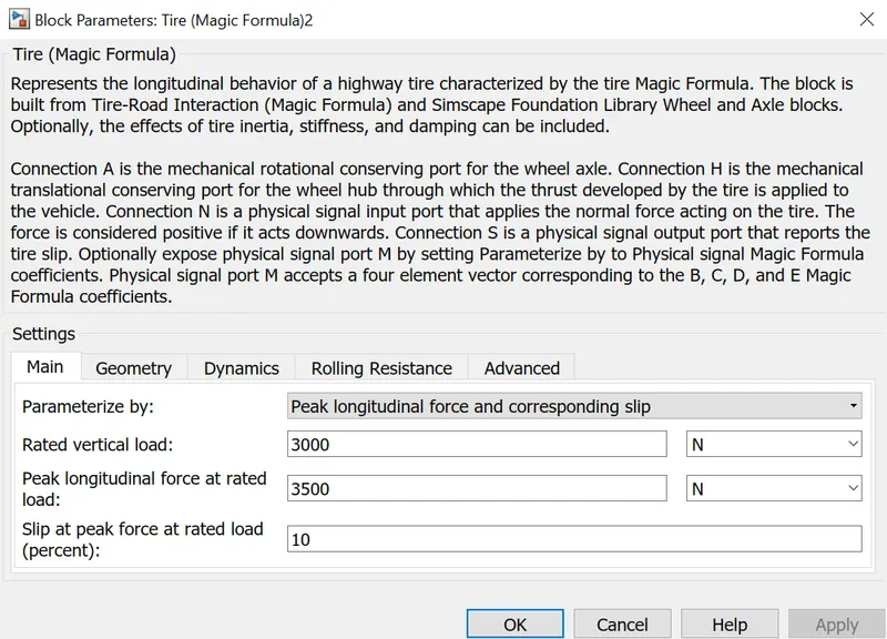
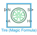 The Tire (Magic Formula) block models the tire as a rigid wheel-tire combination in contact with the road and subject to slip. When torque is applied to the wheel axle, the tire pushes on the ground (while subject to contact friction) and transfers the resulting reaction as a force back on the wheel. This action pushes the wheel forward or backward. If you include the optional tire compliance, the tire also flexibly deforms under load.
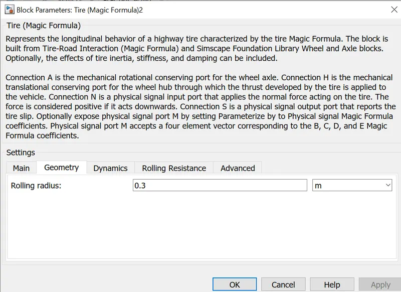
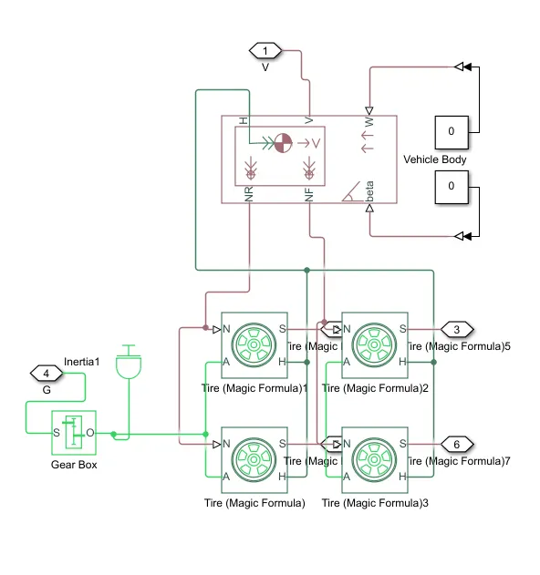
This subsystem is the mechanical part of electric vehicle.its made up of four tires(magic formula).in the groups hub(H) and axle(A) is connected of two tires for rear and front wheel.Hub of the two groups are connected and sends to the hub(H) port of the vehicle body.Rotation(N) of two wheels is connected for rear wheel portion to NR and another two wheels is connected for frontal wheel portion to NF of vehicle body respectively.As the vehicle is rear wheel drive so connected axile of rear wheels is connected to a gearbox and an inertia is added to it.
GEARBOX

The block represents an ideal, non-planetary, fixed gear ratio gear box. The gear box is characterized by its only parameter, Gear ratio, which can be positive or negative. Connections S and O are mechanical rotational conserving ports associated with the box input and output shaft, respectively. The gear ratio is determined as the ratio of the input shaft angular velocity to that of the output shaft.The block generates torque in positive direction if a positive torque is applied to the input shaft and the ratio is assigned a positive value.
Inertia
 represents the mechanical rotational inertia here .01kgm^2 as inertia.
An inertia block has been added to provide ideal mechanical rotational inertian for gear box.the mechanical rotaional conserving port is directly connected to the gearbox.
Vehicle Body
The Vehicle Body block represents a two-axle vehicle body in longitudinal motion. The vehicle can have the same or a different number of wheels on each axle. For example, two wheels on the front axle and one wheel on the rear axle. The vehicle wheels are assumed identical in size. The vehicle can also have a center of gravity (CG) that is at or below the plane of travel.
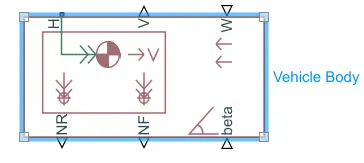
The six ports in the vehicle body are
H this is the hub and is connected to tires to the main body of the vehicle.
V This is a signal output port to measure the velocity of the vehucle which is connected to vehicle feedback of the longitudianl driver through a ps converter and to a scope to measure the velocity.
W This is a physical signal input port which is connected to a constant via ps converter.
NR This is a physical signal output port which is connected to model the rear wheel normal force.
NF This is a physical signal output port which is connected to model the front wheel normal force.
beta This is a physical signal input port which allows to create inclination angle which helps to climbing force.here zero is connected as we are not considering hill climbing.
The block parameters are changed accordingly
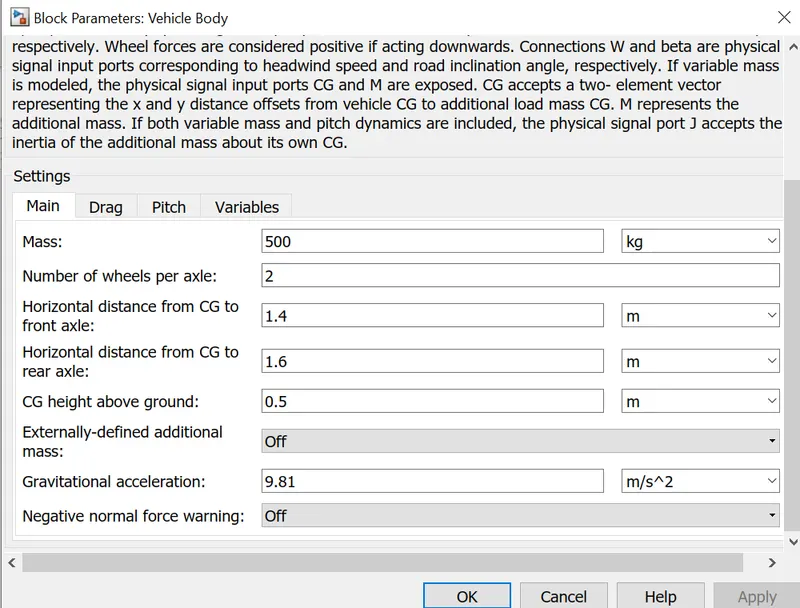
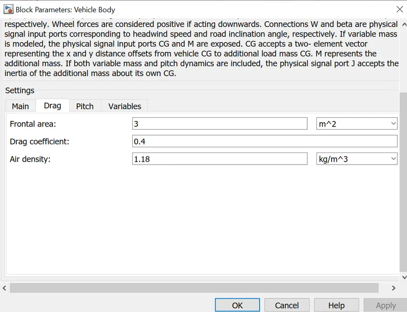
OUTPUT
Battery output graph
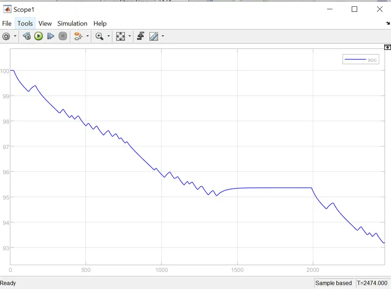
It is clearly visible from the graph that at initial point the battery charge was at 100 % and then it decreases to 90 % at 2472 seconds.As further increase in simulation time decreases the battery charge. so the capacity of the battery can br set as per the requirement.
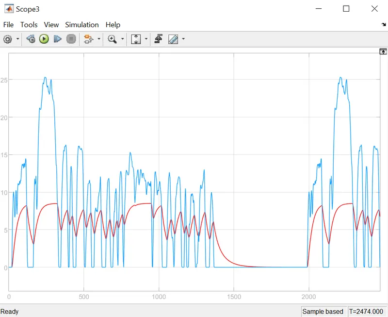
The blue line represents the input and the red line dispalya the output speed of the electric vehicle.It can be concluded that the output is trying to reach as accurate value of input but as we have given varied parametres in dc motor and H bridge the output is trying to achive as per the input.By changing the rated load and dc supply the output can be achieved as input.
Current Output
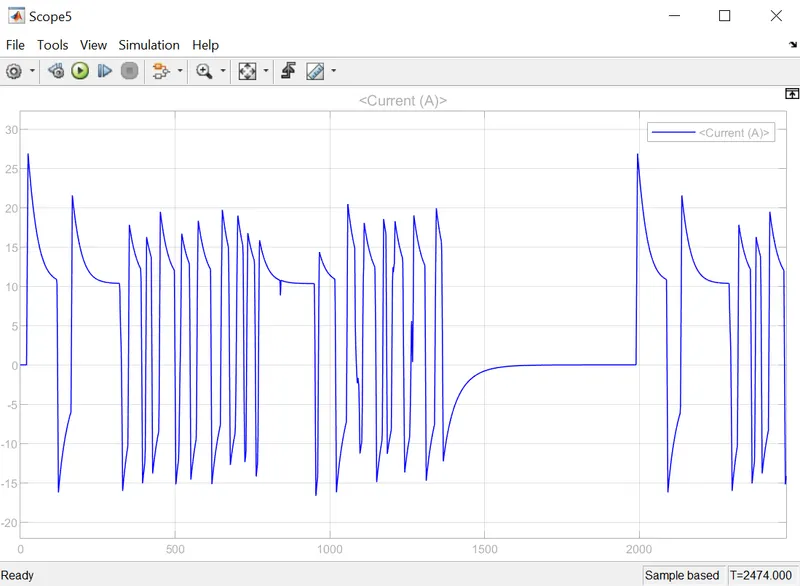
The current value is between -5 to 25 Amperes.
Voltage Output
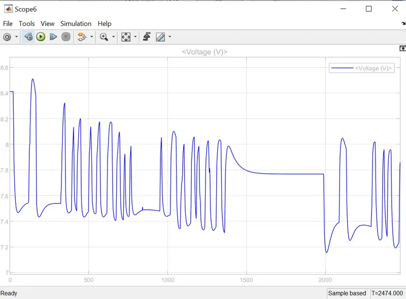
The voltage value is between 7.2 to 8.5 volts
State of charge for lithium ion battery
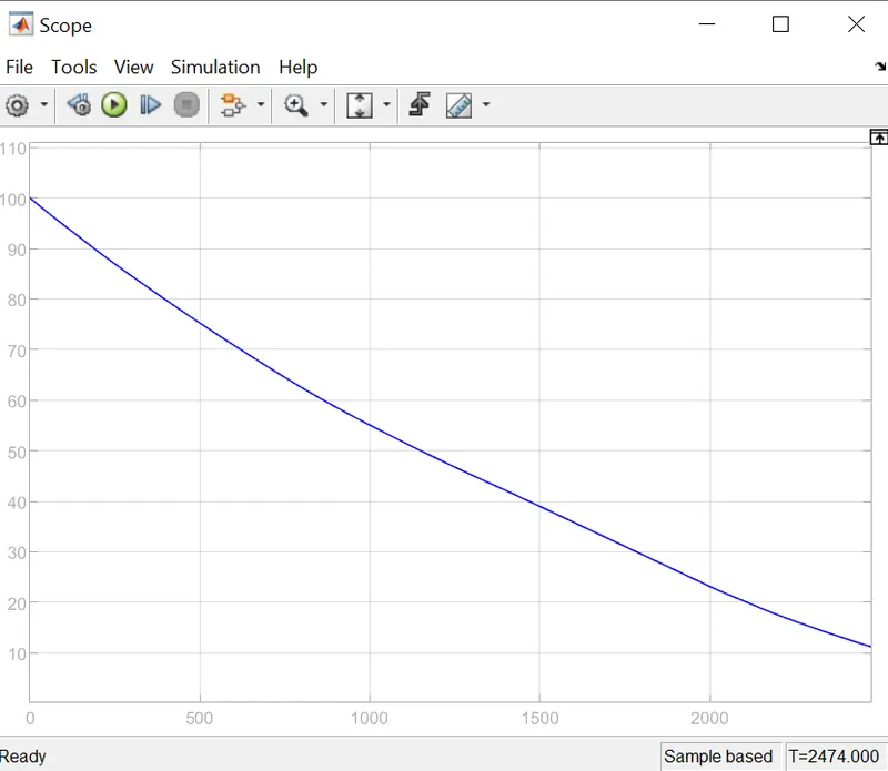
The Battery comes to a 10 % when the vehicle runs for 2474 seconds or 98 kilometers.
The 98 kilometers estimation is taken from the average energy calculation where it multiplies voltage and current to calculate the power and integrates to produce the driving kilometers that can be attained by the lithium ion battery.
CONCLUSION
The EV has obtained an output according to the FTP75 Drivecycle and it can be tested .The Esimation kilometers and state of charge is calculated by a lithium ion battery.
In real time the battery capacity can be increased and can travel more distance.The real time outputs may vary from the design as considering the wind, rain and other factors in reality.
The file of the final project of Design of an Electric Vehicle is uploaded