Week -2
AIM
To build a simulink model of doorbell using solenoid and bell should work for 2 seconds simultanusly.
To use a thermistor to sense the temperature of a heater and to work according to the given conditions
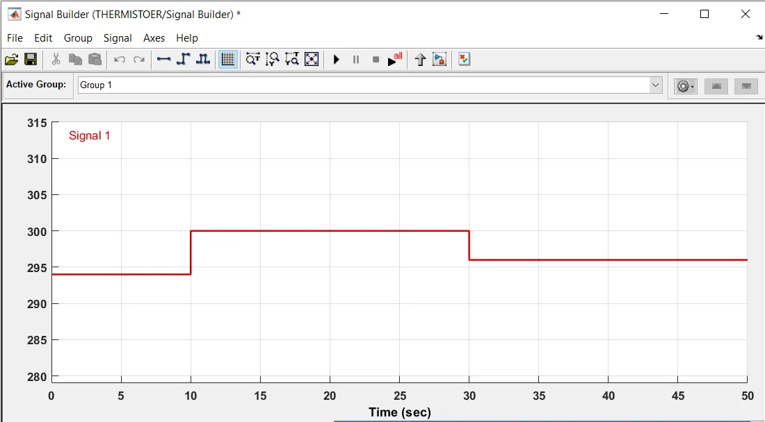
Temperature source: 20 °C from 0 to 10 seconds, 27 °C from 10 to 30 seconds, 23 °C from 30 to 50 seconds
Fan conditions: ON if the temperature above 25 °C, OFF otherwise
THEORY
A doorbell is a complete electrical circuit that allows household electricity to flow through doorbell's internal electromagnet. The magnetic field generated by the electromagnet is then used to power mechanism that creates the sound.
SOLENOID DOORBELL
Doorbell mechanism that employs only one solenoid to achieve both single tone and double tone operation. The solenoiod has a split coil with the full coil being employed for double tone operation and a portion of the coil being employed for single tone operation.
PROCEDURE for doorbell.
A pulse generator is used to give the inputs
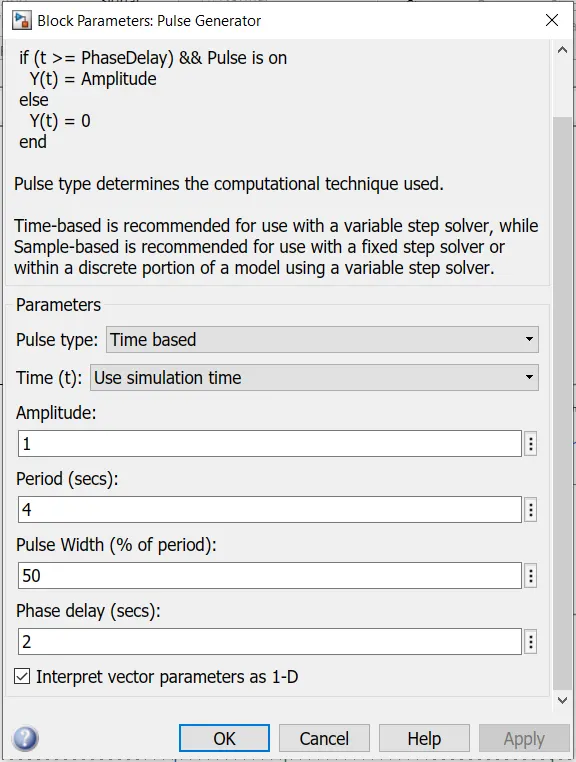
Then from the input is connected to a switch and to a battery which is connected with the solenoid.in order to obtain less damping effect the spring constant value are reduced.
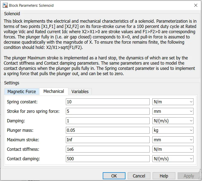
The output of the solenoid is connected to the ideal translational motion sensor in order to sense the motion.PS and SP converters are used to convert physical and simulink datas.
The circuit is connected to mechanical translational reference in order to ground or fix.for solving the mathematical equations solver configuration is added and an electrical reference for the supplyt.
The output is connected to a scope to obtain a plot.
INPUT
Input signal is trggered for every 2 seconds.

Simulink Model
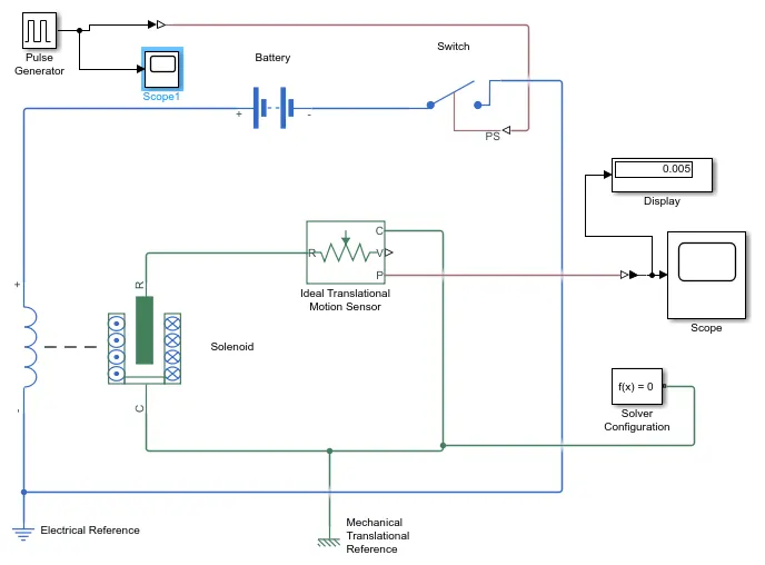
Battery supply the current and the switch is closed for 2 seconds.when the current passes through the solenoidthe plunger moves from 5mm to 0mm.
The motion of the plunger is sensed by the motion sensor and the output is plotted in the scope.
OUTPUT
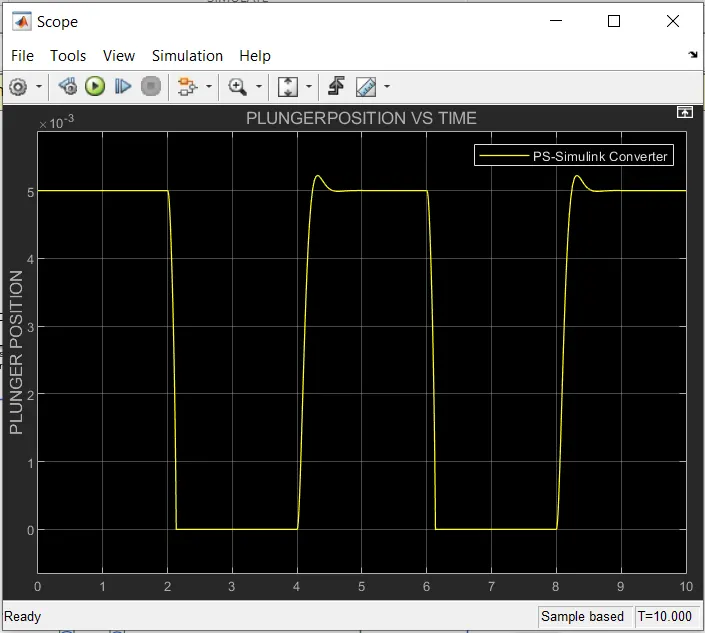
The oputput graph clearly shows that the switch is on for 2 seconds and off for 2 seconds simultanously.
THERMISTOR
A thermistor is a thermally sensitive resistor that exhibits a precise and predictable change in resistance proportional to small changes in body temperature. How much its resistance will change is dependent upon its unique composition. Thermistors are part of a larger group of Passive components. And unlike their active component counterparts, passive devices are incapable of providing power gain, or amplification to a circuit.
PROCEDURE
Signal builder - Here a signal builder block is made for controlled temperature source.for 0-10 seconds 273k , 10-30 seconds 300k and 30-50 seconds 296 kelvin.
Input signal
SIMULINK MODEL
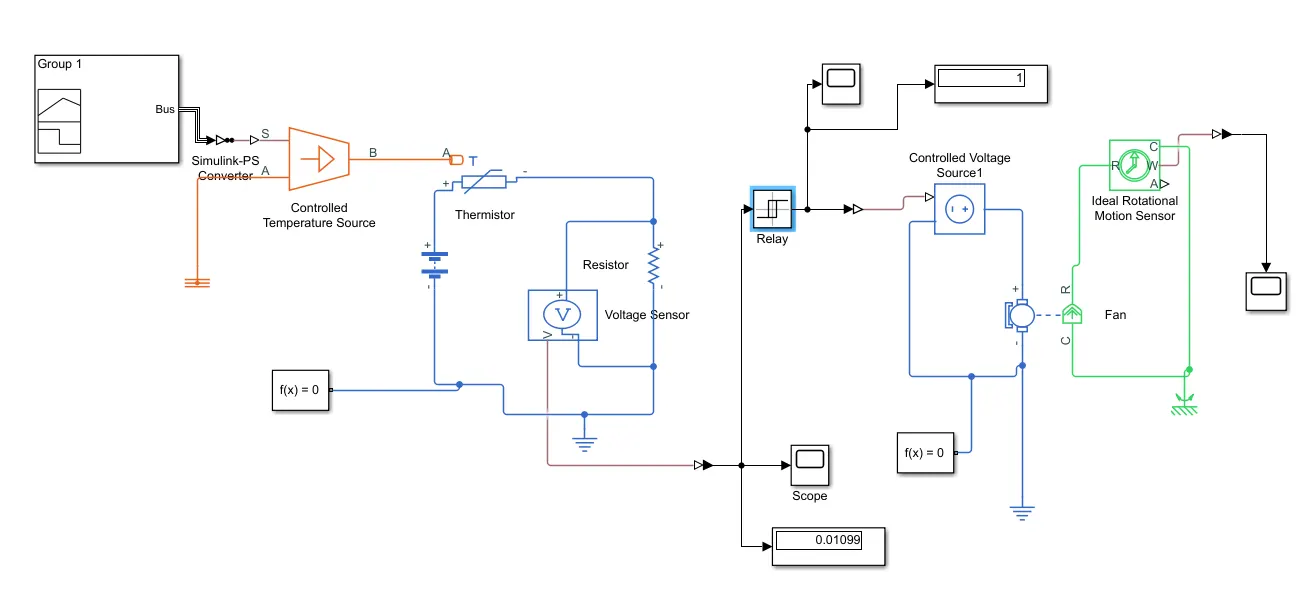
The temperature of the SOURCE is connected to a thermistor inorder to sense the temperature.when the temperature reaches 25 degrercelcius or 298k kelvin the circuit must be trigered with some extenal power such as battery and for the resistance an external resistor is connected to thermister inorder to run the fan.A voltmetre is connected to check the voltage and to supply the threshhold value to switch the fan on.The relay indicates the on off stage.then the connection goes to controlled voltage source where the fixed voltage vs is supplied to the DC motor fan.An ideal motion sensor is used to sense the motion.electrical references and mechanical rotational sensor are used inorder for appropriate circuit connections.There are three scopes connected to the three ports of output states.
OUTPUT 1
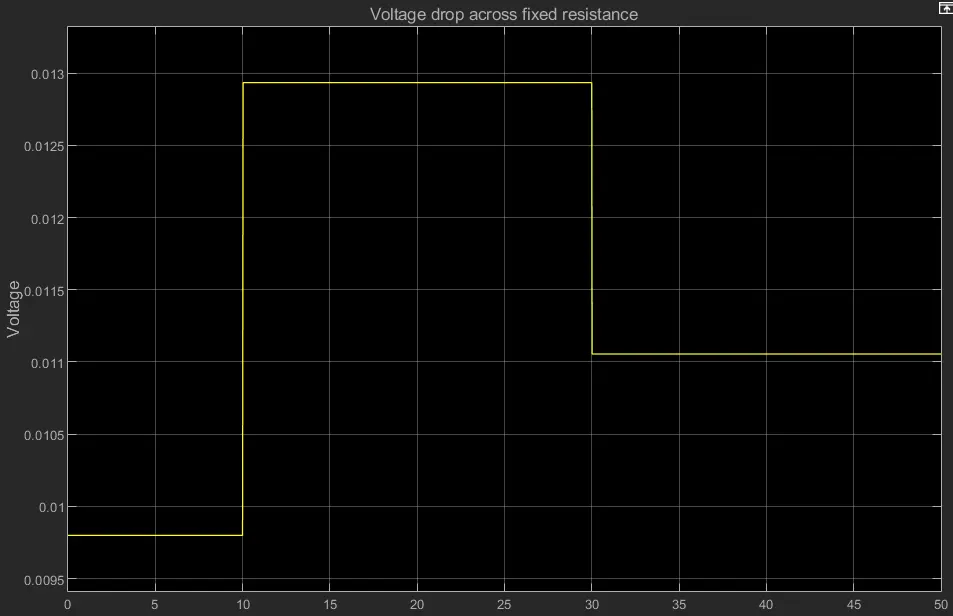
Here the graph indicates voltage drop across the fixed resistance.
OUTPUT 2
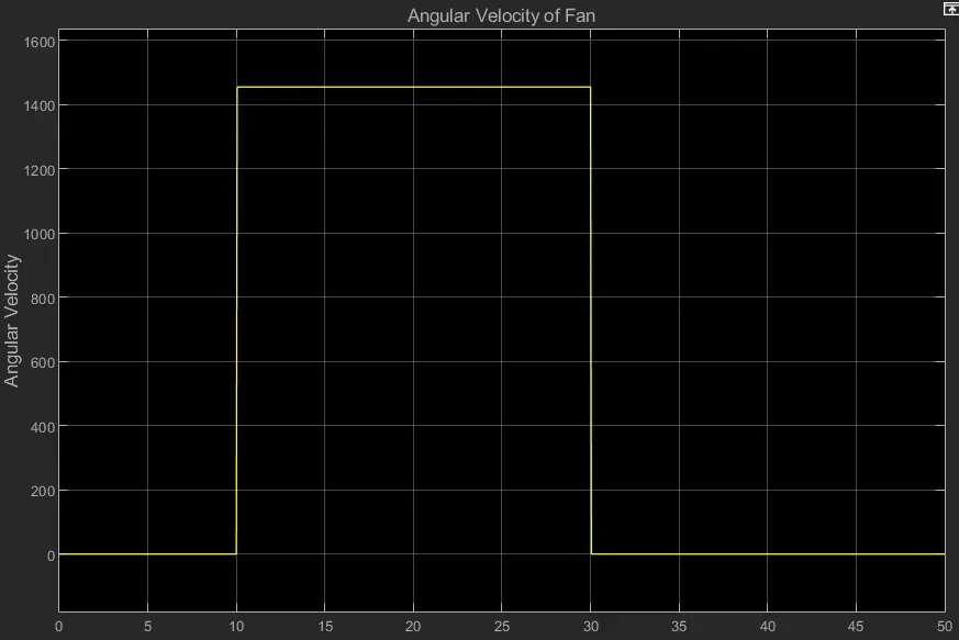
This graph represents the angular velocity with respect to time where the fan rotates at a highest speed in between 10 to 30 seconds.
CONCLUSION
From the both graph we can conclude that the fan is only when the temperature exceeds 25 degree celcius.