Project-1: Modelling an electric Car with Li-ion battery
AIM
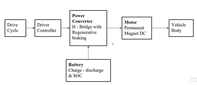
Create a MATLAB model of electric cae which uses lithium ion battery and suitable motor.Choose suitable blocks from simscape of powertrain block set.Implement the vehicle speed control using PI controller and generate brake and accelerator commands.Avoid using readymade driver block for speed control
INTRODUCTION
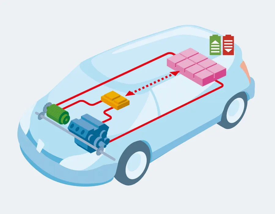
An electric vehicle is vehicle which uses battery power as a power source .It uses electric motors for propulsion of the vehicle .The electricity stored in the battery and it is used to power the electric motors and battery can be recharged .They are categorised into three different types battery electric vehicles , Plugin hybrid electric vehicle and Hybrid electric vehicle
Battery Electric Vehicle
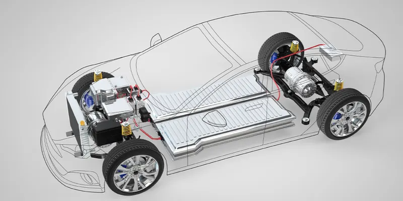
Battery electric vehicles are full electric vehicles with rechargable batteries and an electric motor with no combustion engine . It stores power in battery and this power is used to run the vehicle and other electronics present in the vehicle .These vehicles can be charged by electricity from external power source .These vehicles range for moderate km per charge .They dont emit any hazardous emissions .Some of the best examples of these cars are tesla , toyota pruis , tata nexon EV
Plug in Hybrid Electric Vehicle
These types of vehicle have both electric motor and an internal combustion engine .They have batteries that can be charged with regenrative braking or with a external power supply .These vehicles can go from 10-30 on a average with electric motor before the assitance of a an combustion engine .Some of the best examples of these cars are toyota camry hybrid, Honda civic hybrid ,Volvo XC90 , maruti suzuki ciaz mild hybrid .

Hybrid Electric Vehicle
These types of vehicle get powered by both electric motor and internal combustion engine .Battery can be recharged with regenrative braking only .Electric motor supplies for starting and the internal combustion takes place when there is heavy load and on high speed .Controller is used to ensure the best economy.Some of the best examples are honda accord hybrid , Hyundai sonata hybrid ,Toyota camry Hybrid
Benefits of Electric Vehicle
- An electric vehicle has fewer moving parts than a conventional petrol / diesel car .Servicing is relatively easy less frequent and overall cheaper to maintain a electric car when compared to a petrol/diesel vehicle
- All EV batteries degrade it becomes less efficient .Most car manufacture give an warrant for the batteries that will npt degrade below a certain level for around 10 years .It is also necessary to replace a battery in a EV in time after years
- The cost of electricity required to change an EV is around 40%-60% less than the cost of the petrol for a similar sized vehicle driving for a same distance.The cost will get very lower when charging the vehicle at free charging station too
- They produce no air pollution and it will decrease warnings
Model View
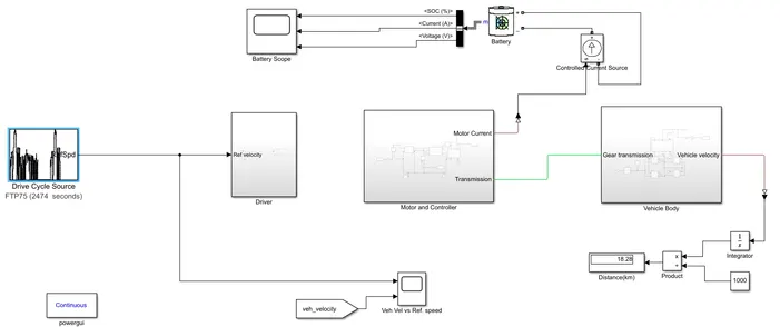
Introduction
For this model we have used PID controller which is directly taken from the library and tuned it as per the vehicle requirement or can make manual PID . I have made both the things but the value of P,I,D is the same as per the tuned value
Driver Block
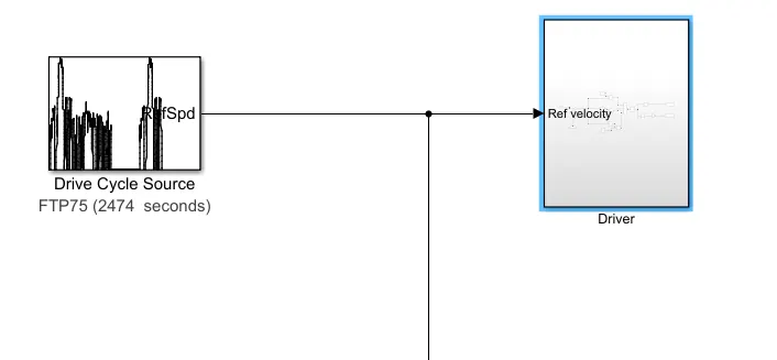
Driver block Subsystem
In this driver block system we used PID controller for tuning the reference velocity and running velocity
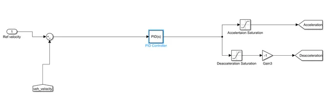
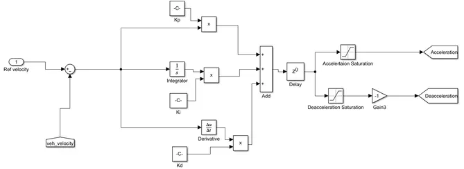
Manual PID Controller
In this model we have made the PID controller by constant , integrator and derivative blocks .But the values which have taken by PID controller blocks after tuning .To check that manual made PID controller are same or not
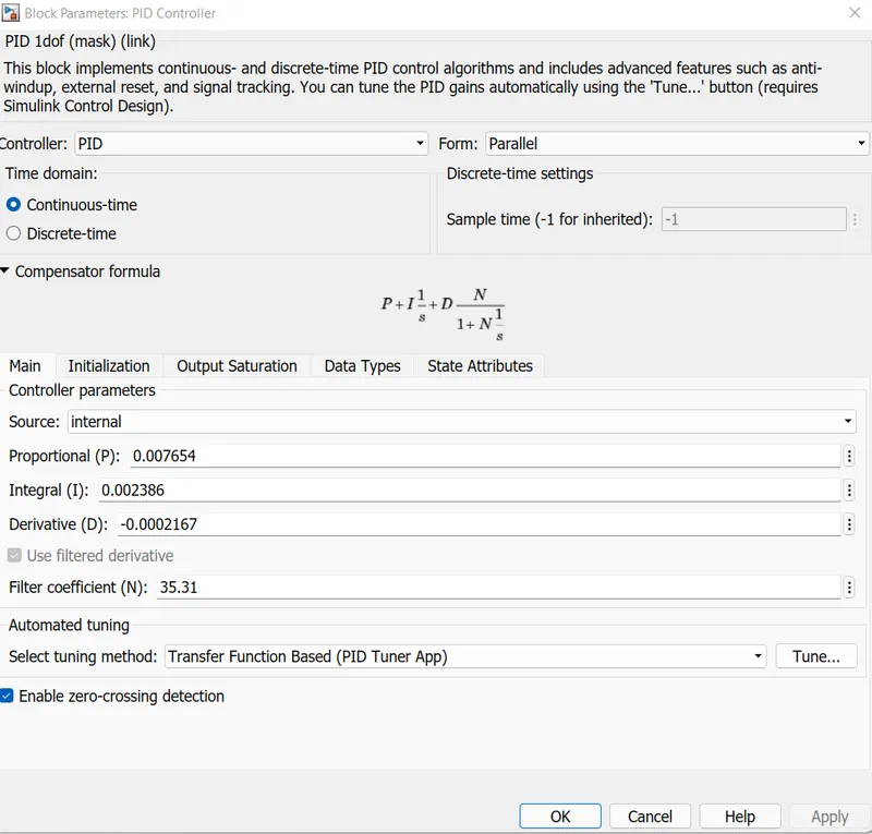
PID Controller
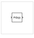
The PID controller block implements a PID controller .The block is identifical to the discrete PID controller block with the time domain parameter set continous time
The block output is a weighted sum of the input signal the intergal of the input signal and the derivative of the input signal .The weights are proportional inetrgal and deriavative gain parameters .A first order pole filters the derivative action
The block supports several controller types and structures .Configurable options in the block include
- Controller type (PID,PI,PD,P only I only) - see the controller parameter
- Controller type (Parallel or ideal) - See the form parameter
- Time domain (Continous or discrete ) See the time domain parameter
- Intial conditions and reset trigger - See the source and external reset parameters
- Output saturation limits and built in anti windup mechanism - See the limit output parameter
- Signal tracking for bumpless control transfer and multiloop control - See the enable tracking mode parameter
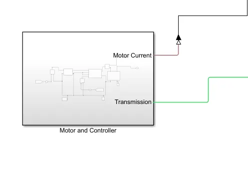
Electrical Circuit Subsystem
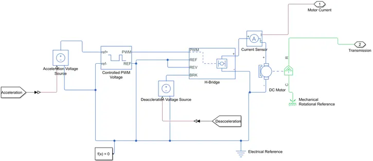
Controlled PWM Voltage
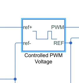
- Electrical input ports - The block calculates the duty cycle based on the referene volatge across its ref+ and ref ports .This modelling variant is the default
- PS input - Specify the duty cycle value directly by using an input physical signal port
- Next have a controlled PWM voltage to provide a controlled pulse width modulated volatges to the H bridge block.The pulse of voltage created by this block are dependent on the duty cycle which is in that ratio of the time that the switch is ON to the time taken for one cycle .The duty cycle formula is given by
Duty Cycle - Ton /(Ton+Toff)
For the electrical input parts variant of the block the demanded duty cycle is
100 * Vref -VminVmax -Vmin percent
Where
- Vref is the reference voltage across the ref + and ref - ports
- Vmin is the minimum reference voltage
- Vmax is the maximum reference voltage
The value of the output voltage amplitude parameter determines amplitude of the output voltage
At time zero the pulse is initialized as high unless the pulse delay time parameters is greater than zero or the demanded duty cycle is zero
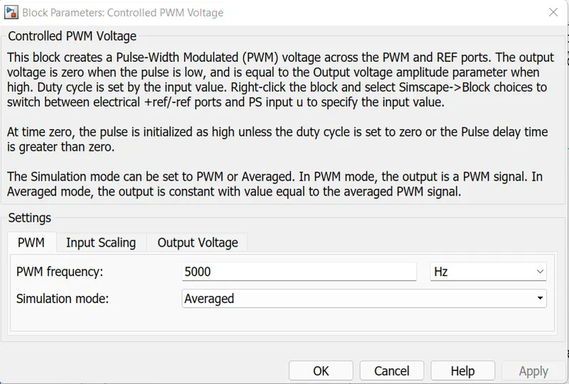
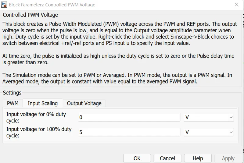
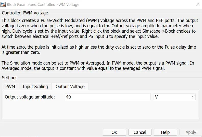
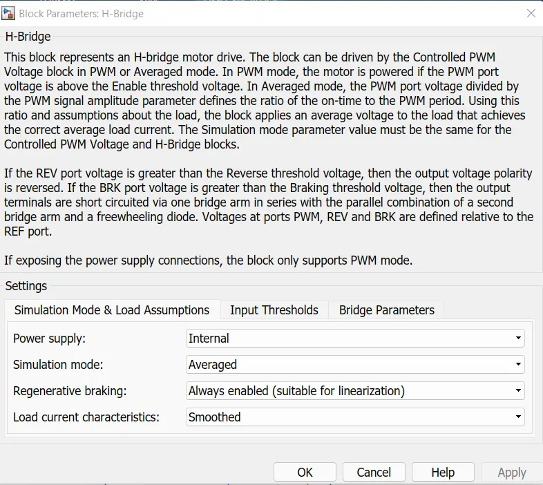
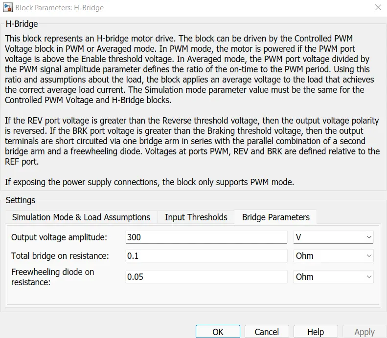
Hbridge
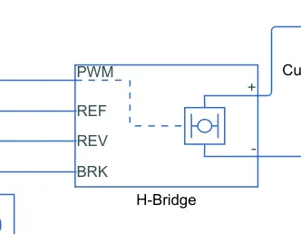
The H-Bridge block represents on H-bridge motor driver .The block has the following two simulation modes options
- PWM The H-Bridge block output is a controlled voltage that depends on the input signal at the PWM port .If the input signal has a value greater than the enable thresold voltage parameter value ,the H-bridge block output is an and has a value equal of the output voltage amplitude parameter .If it has a value less than the enable thresolfd voltage parameter value the block maintains the load circuit using one of the following three freewheeling mode options
If the PWM frequency is large enough .Synchronous opeartion where freewheeling is via a bridge arm back to the supply also helps smooth the current.For cases where the current is not smooth or possible discontinous use the unsmoothed or discontinous option.For this option you must also provide values for the total load series resistance total load series inductance and PWM frequency .During simulation the block uses these values to calculate a more accurate value of H-Bridge output voltage that achieves the same average current as would be present if simulating in PWM mode
DC Motor
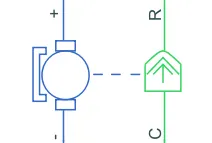
The DC motor represents the electrical and torque characterstics of a DC motor using the following equivalent circuit model
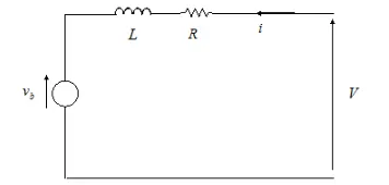
You specify the equivalent circuit parameters for this model when you set the model parameterized to by equivalent circuit parameter .The resistor R corresponds to the resisstance you specify in the armature resistance parameters.The induction L corresponds to the inducatnce you specify in the armature inductance parameter
You can specify how to generate the magnetic field of the DC motor by setting the field type parameter to the desired option .The permanent magnet in the motor induce the following back emf Vb in the armature

Where Kv is the back emf constant and w is the angular velocity .The motor produces the following torque which is propotional to the motor current i
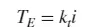
Where k1 is the torque constant .The DC motor block assumes that there are no electromagnetic losses .This means that mechanical power is equal to the electrical power dissipated by the back emf in the armature .
Equating these two terms gives
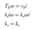
As a result you specify either kv or kt in the block parameters
If the magnetic field is generated from the current flowing through the windings the back emf constant depends on the field current
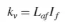
Where Laf is the field armature mutual inductance
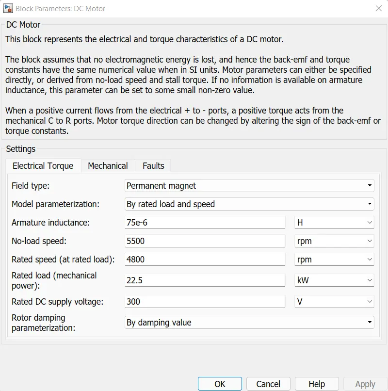
The torque speed characterstics for the DC motor block is related to the parameter in the preceding figure.When you set the model parameterization parameter by to stalll torque and no load speed or by rated power , rated speed and no load speed the block solves for the equivalent circuit parameters as follows
- For the steady -state torque - speed relationship .L has no effect
- Sum the voltage around the loop and rearrange for i
Vehicle Body
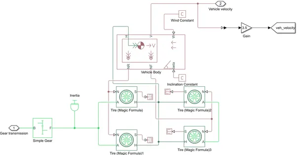
Subsystem of the vehicle body and wheel
The above block is forming a subsystem which serves as a part of the whole vehicle.Four tires are connected where the right two tires are the rear wheels and left two tires are the front wheels .They are interconnected to the hub of the vehicle body block .And thier respective axles are connected accordingly .We here have completed the rear axle with the gear as we want the model a rear wheel drive vehicles .Here the wind velocity part and hill climbing angle parts are connected to physical constant blocks which is kept as zero
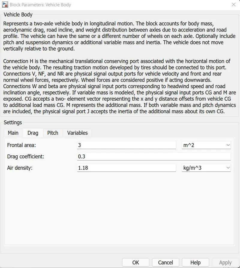
Vehicle Body
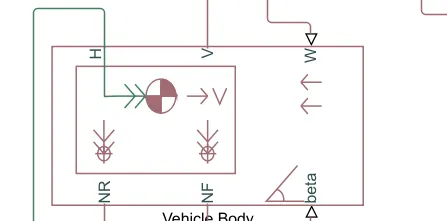
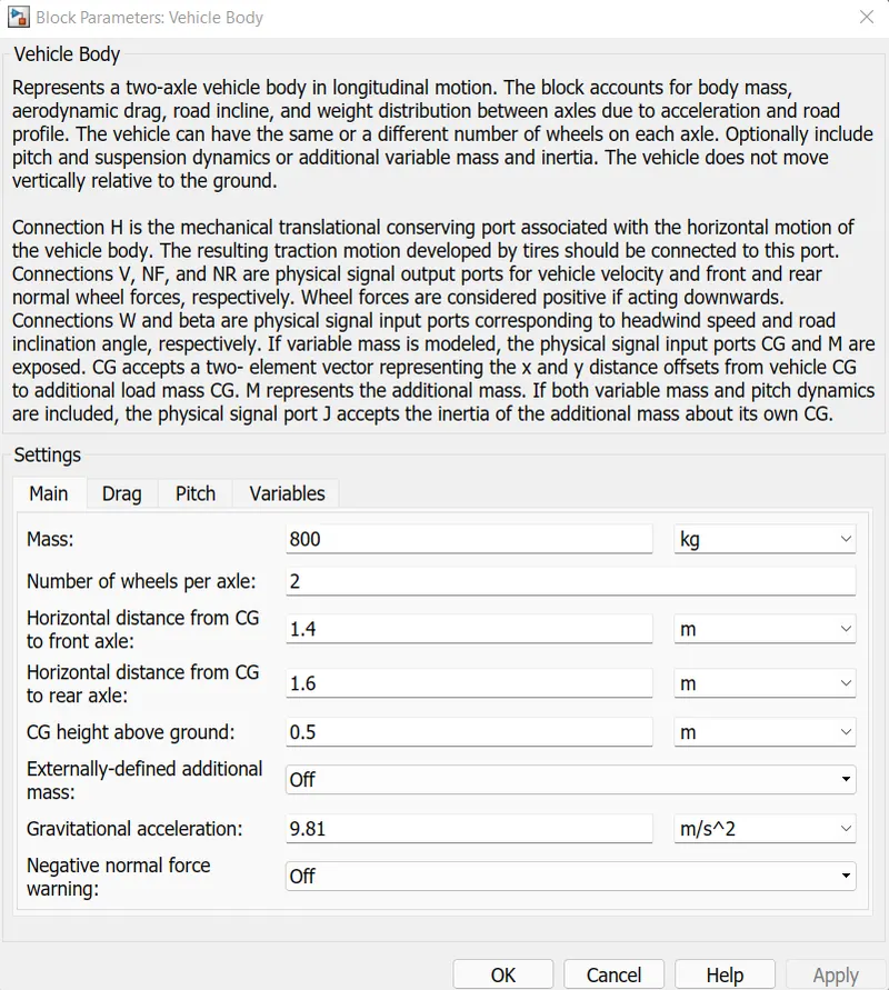
The vehicle body black represents to a two axle vehicle body in logintudinal motion.The vehicle can have the same or a different number of wheels on each axle .For examole two wheels on the front wheels on the front axle and one wheel on the rear axle .The vehicle wheels are assumed identical in size .The vehicle can also have a center of geavity that is below the plane of travel
The block accounts for body mass , aerodynamic drag , road incline and weight distribution between axles due to accelaration and road profile .Optionally include pitch and suspension dynamics .The vehicle does not move vertically relative to the ground
The block has an option to include an externally defined mass and externally defined inertia .The mass inertia and center of gravity of the vehicle body can vary over the course of simulation in response to system changes
This block contain 6 ports which can be used to model various aspects of the vehicle body .The parts are mentioned below
- H stands for hub and is used to connects the hubs of wheels to main body of the vehicle
- V physical signal output port which stands for velocity and is used the output the velocity of the vehicle
- W physical signal port and allow us to model a wind velocity that acts against the vehicle
- NR physical signal port to connect to the rear wheels
- NF physical signal port to connect the front wheels of the vehicle
- Beta physical signal input port which allow the vehicle to undergo an inclination of hill climbing force
Tire (Magic Formula)
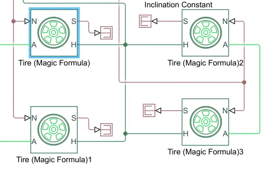
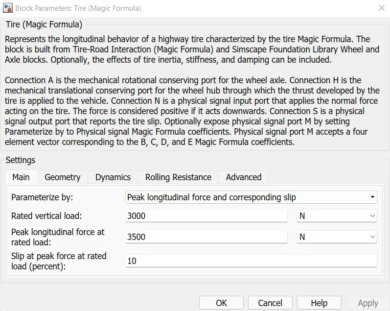
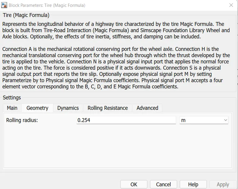
The tire block models a tire with longitudnal behaviour given by the magic formula an empirical equation based on four fitting coefficients .The block can model tire dynamics under constant or variable pavement conditions
The longitudnal direction of the tire is the same as its direction of motion as it roll on pavement .This block is a structural component based on the tire road interaction block
To increase the fidelity of tire model you can specify properties such as tire compliance , inertia, and rolling resistance .However these properties increase the complexity of the tire model and can slow down simulation .Consider ignoring tire compliance and inertia if simulating the model in real time or preparing the model for hardware in the loop simulation
- Connection A is the mechanical rotational conserving port of the wheel axle
- Connection H is the mechanical rotational conserving port of the wheel hub through which thurst developed
- Connection N is the physical signal input port that applies normal force acting on the tire
- Connection S is the physical outport that reports the tire slip
Simple Gear
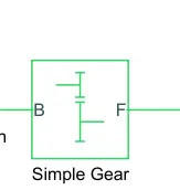
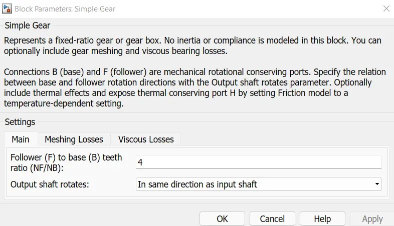
This block models a gear system with fixed gear ratio with no interia effects .However we can modify the messing of the gear teeth , Here the follower to base teeth ratio has been set to 2 and the output shaft rotates in the same direction as the input shaft
These blocks are forming a subsystem whuch serves as a part of the whole vehicle.Four tires are connected where the right two tires are front wheel and the two tires are rear wheel.They are interconnected with the vehicle by the hubport and the axle are also connected accordingly .Here we have connected the rear axle with gera as we want the model to be a rear wheel drive vehicle
Battery System
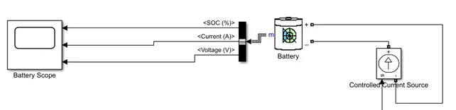
The battery will be the energy store of the EV and will contain the electrical energy in DC form and provides this energy to operate
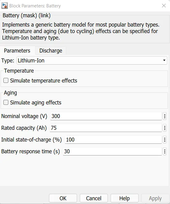
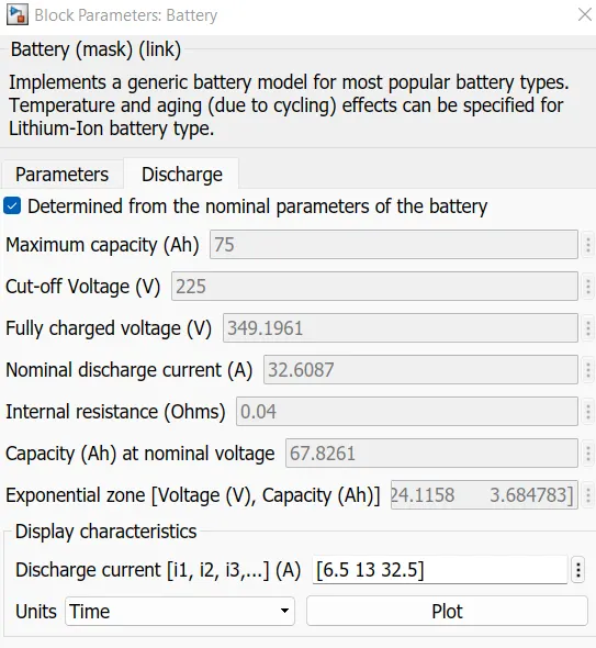
The battery will be the energy store of the EV and will conatin the electrical energy in DC form and provide this energy to operate
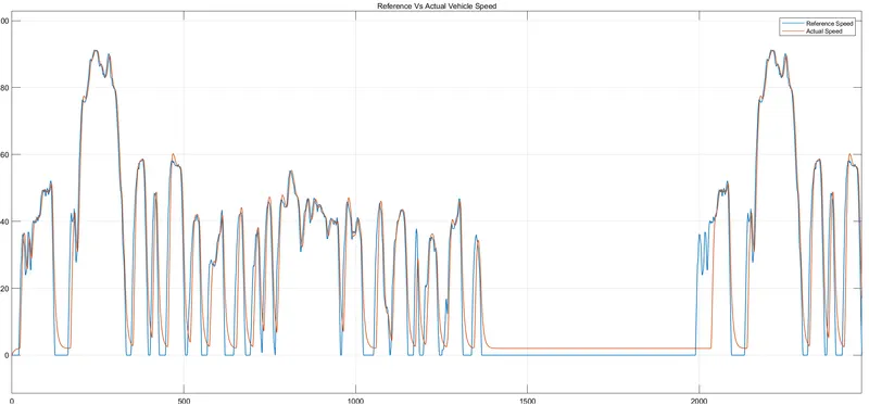
Result Model is as per PID controller block
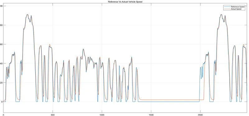
Here we have our first graph reference voltage and feedback voltage .So our running velocity is following the reference velocity
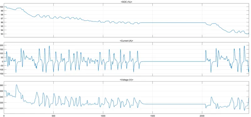
Battery Parameters
Here we have the battery performance output for the driving cycle at where our SOC become 93% during the whole cycle .Battery current varies as per the driving the vehicle same as for battery voltage
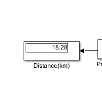
Distance covered
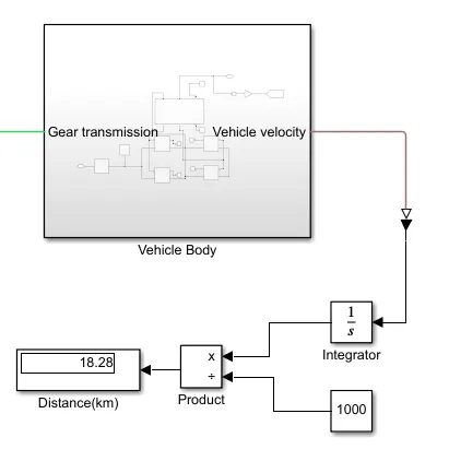
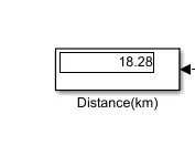
During this driving cycle for 2474 sec it covers the 18.28Km of distance with maintaining 93% of SOC
Result(2) Model is as per manual made PID controller
Here we have our first graph of reference voltage and feedback volatge .So our running velocity is following the reference velocity
Battery Parameters
Here we have the battery parameters output for the driving cycle at where our SOC become 93% during the whole cycle .Battery current varies as per the driving of the Same as for battery vehicle

Distance covered
During this driving cycle for 2474 sec it covers the 18.28km of distance with maintaining 93% of SOC
CONCLUSION
- We have made the model by PID controller by two techniques where the first one is by taking direct PID controller and the second one where we had made the manual PID controller where we can feed the manual data of the same
- By making this graph we have the same P,Iand D value which have gave through the tuning of the PID .So by this method by manual PID will also check that working properly or not
- By Both method our distance covered 18.28 Km
- In both cases SOC value is 93% which is ok per the driving cycle.