Project-1: Modelling an electric Car with Li-ion battery
AIM :
- To make an Electric car model which uses li-ion battery in MATLAB simulink environmnet.
OBJECTIVE :
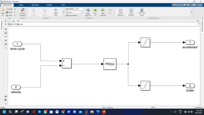
- Create a MATLAB model of electric car which uses lithium ion battery and suitable motor. Choose suitable blocks from Simscape or Powertrain block set. Implement the vehicle speed control using PI controller and generate brake and accelerator commands. Avoid using readymade driver block for speed control.
- Prepare a report about your model including following:
- Objectives, System level configurations, Model parameters, Results, Conclusion
Methodology :
- The electric vehicle consists if a battery,motor,controller then its generates propulsion power.
- to design an EV first we need to calculate propulsion power then we will select motor type.
- then we need to select motor and battery for suitable range and vehicle parameters.
- in market many types of motor,controller and battery avaiable.
- so,here we are selecting li ion battery and DC motor.
Introduction :
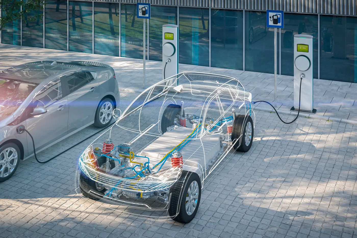
The main work of vehicle is to move people,goods or anything we want from one place to another place.we can do this work by many option ike we can use of animals,use of boat,plane,train and vehicle.in vehicle we can use two wheeler,three wheeler, four wheeler, trucks,crains,etc...and these vehicle are conventional like they use petrol,diesel fossil fuel,some are using gas(LPG,CNG,etc),but its harmfull for environment and it will create pollutonlike Air aswell noice pollution.so what i am trying to say is we just need to go one to another direction so why we cant use that things which is pollution free,have a enough speed,less cost,high torque,and human friendly.so for that we can add electric vehicle in this list.apart from this we can use HEV(hybrid electric vehicle),fuel cell vehicle by using hydrogen as fuel cell,ethanol based vehicle and in future we can find many options aswell.
An electric vehicle (EV) is defined as a vehicle that uses an electric motor or a traction motor for propulsion as opposed to an internal combustion (IC) engine used by conventional vehicles. Electric vehicles use electricity for power instead of fossil fuels as conventional vehicles would and because of this difference, electric vehicles do not produce any exhaust gases or pollution. The power needed for the operation of an EV can come from a variety of sources such as batteries, generators, or through a collector system. Batteries fitted in to the body of an EV are capable of high energy densities in order for them to meet the power demands and range requirements. Generators are machines which generate electrical energy from an input of mechanical work and are a part of the electric motor, and they operate during braking to produce the phenomenon of regenerative braking. Collector systems are off-vehicle systems which allow for the charging of an EV from homes or public charging stations. The electricity used for charging in these systems are generated from solar panels which can be used by the grid or by homes of EV owners so that they can charge their vehicles more conveniently.
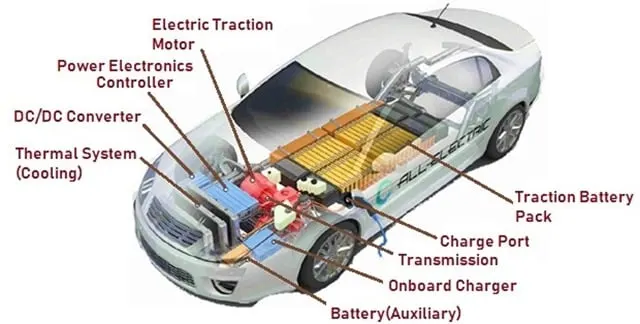
EVs offer several advantages over conventional vehicles besides the lack of pollution and lack of need to rely on fossil fuels. One is that, EVs are more efficient meaning that they offer more miles per gallon gasoline equivalent, meaning that you will spend lesser on recharging an EV than you would to refuel a conventional vehicle. This because the more efficient the EV is, the more distance you travel with the available energy. In the US, Tesla owners can charge their EVs for free at their private charging stations for life which results in significant savings in fuel. Regenerative braking in EVs adds to their efficiency as the unused energy in braking gets reused purposefully. Another benefit is that EVs have fewer moving/rotating parts and this means lesser maintenance costs than you would have with IC engine vehicles e.g. changing oil, transmission fluid. This, in the long term would give better savings than you would get with conventional vehicles. Lesser moving parts means there is lesser friction between moving parts and hence quieter operation.
A compromise between IC engine vehicles and EVs exists as Hybrid Electric Vehicles. HEVs combine an IC engine with an electric propulsion system to produce a 'hybrid' between the two different classes of vehicles. The purpose of this is to use the power available form the electric powertrain to improve the fuel economy of the vehicle so that it does not rely solely on the petrol/diesel it uses as fuel. This in turn will also improve the overall performance of the HEV. The IC engine can be used to power the electric motor to charge the battery or use directly in the electric drive motor with a combination of a motor and generator in one. HEVs also implement regenerative braking to recharge their batteries among other features used in EVs. Compared to EVs, HEVs represent more of the automotive market with a 19% market share on all automobiles in the world. This is because HEVs still run on fossil fuels which is still more convenient as a fuel source in most parts of the world. The all time best selling HEV to date is the Toyota Prius.
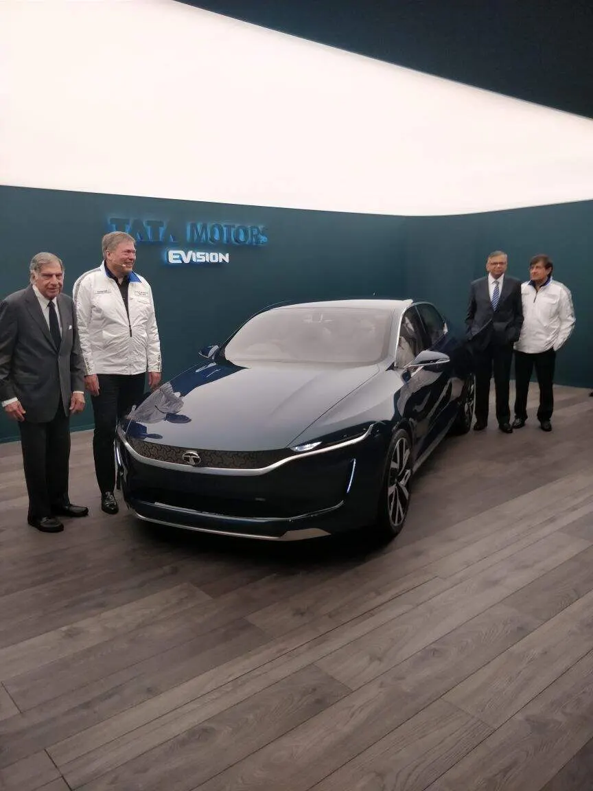
The main components of an electric vehicle are:
- Battery (auxiliary)
- Electric traction motor
- Onboard charger
- Thermal system (cooling)
- Power electronics controller
- Inverter
- Charge port
- Transmission
- DC to DC converter
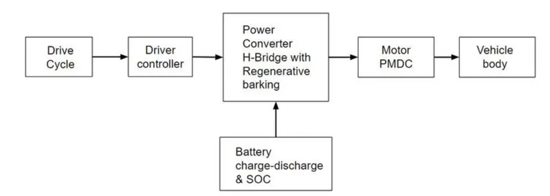
Block Diagram of the Electric Vehicle shown below:
procedure
vehicle body
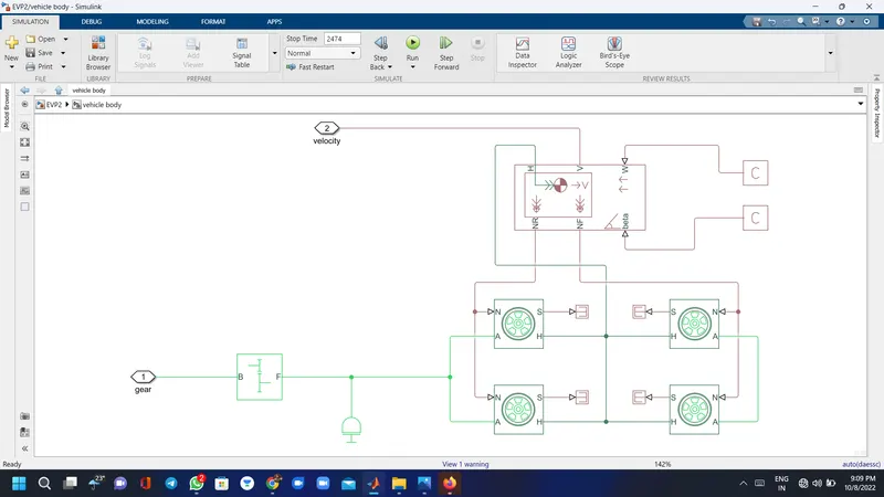
- this subsystem made of tyres,vehicle body. in this subsystem the motor will transfer the power to the simple gear block for smooth and constant speed throughout the trasmission without any loss in speed from motor to tires.
- here we will give motor output to the rear two wheel of the Electric Vehicle and front tire is rotate freely.
- N is the normal force cause by the tires given to the vehicle body normal force port.
- The vehicle body has an H-hub,S-tire slip, N - normal force, A - axel connenction,wind velocity, inclination angle.
- the tire hub is connected as a common node to the vehicle body.The wind velocity and inclination angle is connected to PS constant block.velocity is the output port where we can get at which speed the vehicle is moving and also usefull for the find distance.
motor & controllor
Battery
Driver model
Whole car model
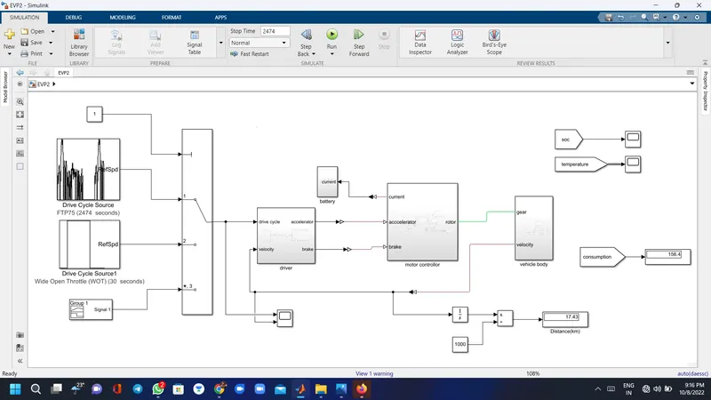
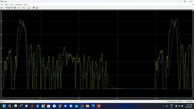
drive cycle results
with FTP75
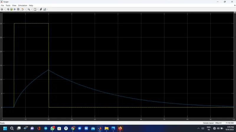
Wot
Signal builder
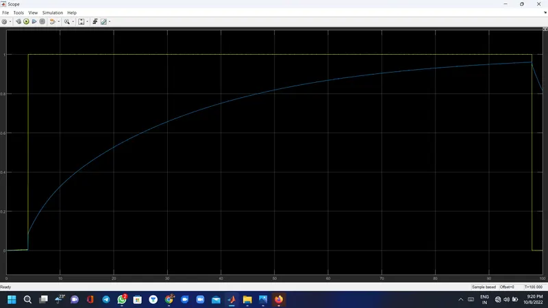
Soc & temperature results with FTP75 drive cycle
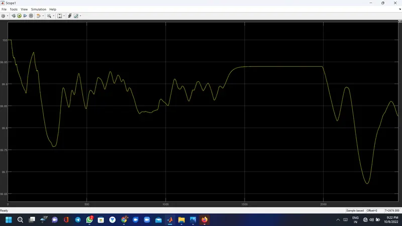
temp
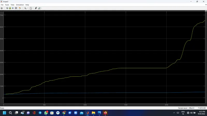
about the blocks
Battery :
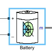
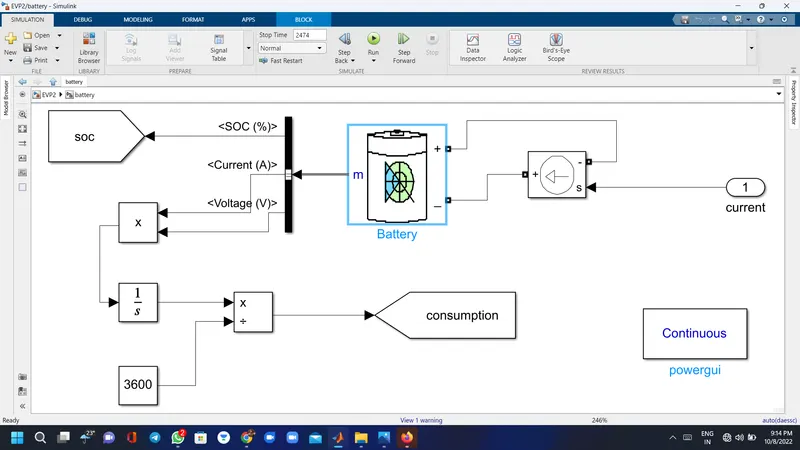
- The battery is required to power the controller and motor.
- The Battery block implements a generic dynamic model that represents the most popular types of rechargeable batteries.
- The battery has two-stage one is charging and another one is discharging state.
- Initial SoC is 100%
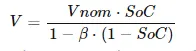
- The battery as a series internal resistance plus a charge-dependent voltage source
- defined by:
Controlled current source :
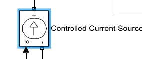
- The Controlled Current Source block converts the Simulink input signal into an equivalent current source. The generated current is driven by the input signal of the block. The positive current direction is as shown by the arrow in the block icon.
- here we can initialize the Controlled Current Source block with a specific AC or DC current. If we want to start the simulation in steady state, the block input must be connected to a signal starting as a sinusoidal or DC waveform corresponding to the initial values.
Bus selector :

- This block accepts a bus as input which can be created from a Bus Creator, Bus Selector or a block that defines its output using a bus object. The left listbox shows the signals in the input bus.
- Use the Select button to select the output signals. The right listbox shows the selections. Use the Up, Down, or Remove button to reorder the selections. Check 'Output as bus' to output a single bus signal.
- here we connected battery input to this bus selector to find current SOC and voltage.
PowerGUI :
- The powergui block allows you to choose one of these methods to solve your circuit:
- Continuous, which uses a variable-step solver from Simulink.
- Discretization of the electrical system for a solution at fixed time steps
- Continuos or discrete Phasor solution
- The powergui block also opens tools for steady-state and simulation results analysis and for advanced parameter design.
DC Motor :
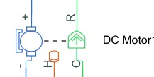
- This block represents the electrical and torque characteristics of a DC motor.
- When a positive current flows from the electrical + to - ports, a positive torque acts from the mechanical C to R ports. Motor torque direction can be changed by altering the sign of the back-emf or torque constants.
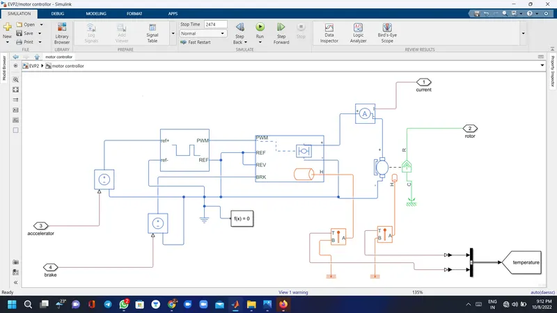
- The Motor controller will get input from the longitudinal driver. It tasks are to control the speed of the motor and drive according to the input of the driver. Majorly motor controlled we designed had two main parts named PWM voltage generator and H-Bridge.
- When deceleration occur this Hbridge will give an output from the positive and negative terminals of it. These negative & positive terminals are later connected to the DC motor and battery. All these components are the simscape electrical components so they need a connection to the solver configuration block which helps to solve the simulation.
- here i am using thermal part aswell to find the motor temperature.
H bridge :
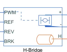
- This block represents an H-bridge motor drive. The block can be driven by the Controlled PWM Voltage block in PWM or Averaged mode.
- here, we are using avaraged simulation mode and smoothed load current to save out simulation time.
- we also use thermal port to find the temperature and + port is connected with voltage and current sensor and PWM and REF connected with controlled PWM voltage and REV and BRK is use for the regerative braking effect.
Controlled PWM Voltage :
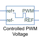
- This block creates a Pulse-Width Modulated (PWM) voltage across the PWM and REF ports. The output voltage is zero when the pulse is low, and is equal to the Output voltage amplitude parameter when high. Duty cycle is set by the input value. Right-click the block and select Simscape->Block choices to switch between electrical +ref/-ref ports and PS input u to specify the input value.
- Electrical input ports — The block calculates the duty cycle based on the reference voltage across its ref+ and ref- ports. This modelling variant is the default.
- PS input — Specify the duty cycle value directly by using an input physical signal port.
- The Simulation mode can be set to PWM or Averaged. In PWM mode, the output is a PWM signal. In Averaged mode, the output is constant with value equal to the averaged PWM signal.
Temperature sensor :
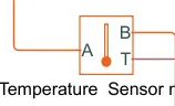
- The Temperature Sensor block represents an ideal temperature sensor, that is, a device that determines the temperature differential measured between two points without drawing any heat.
- Connections A and B are thermal conserving ports that connect to the two points where temperature is being monitored. Port T is a physical signal port that outputs the temperature differential value.
- The block positive direction is from port A to port B. The measured temperature is determined as T = TA – TB.
Gear box:
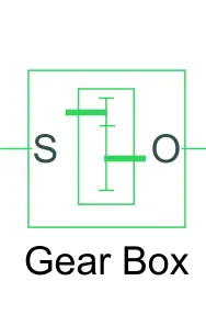
- The block represents an ideal, non-planetary, fixed gear ratio gear box. The gear box is characterized by its only parameter, Gear ratio, which can be positive or negative. Connections S and O are mechanical rotational conserving ports associated with the box input and output shaft, respectively.
- The gear ratio is determined as the ratio of the input shaft angular velocity to that of the output shaft.
- The block generates torque in positive direction if a positive torque is applied to the input shaft and the ratio is assigned a positive value shaft.
Vehicle body :
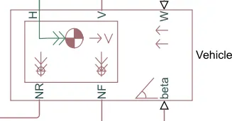
- Represents a two-axle vehicle body in longitudinal motion. The block accounts for body mass, aerodynamic drag, road incline, and weight distribution between axles due to acceleration and road profile. The vehicle can have the same or a different number of wheels on each axle. Optionally include pitch and suspension dynamics or additional variable mass and inertia. The vehicle does not move vertically relative to the ground.
- Connection H is the mechanical translational conserving port associated with the horizontal motion of the vehicle body. The resulting traction motion developed by tires should be connected to this port. Connections V, NF, and NR are physical signal output ports for vehicle velocity and front and rear normal wheel forces, respectively. Wheel forces are considered positive if acting downwards. Connections W and beta are physical signal input ports corresponding to headwind speed and road inclination angle, respectively
- here,we dont include angle and wind velocity so we give constant block there and give velocity V as output and NF,NR,H connected with tyre block.
Tire :
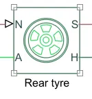
- Represents the longitudinal behavior of a highway tire characterized by the tire magic formula.the block is built from tire road interaction(magic formula) and simscape founation library wheel and axle blocks.optinally we can include rolling resistance,inertia and damping can be included.
parameters

Conclusion :
- succesfully Created a matlab model of electric car.
- Prepared a report about system level configuration,model parameters.
- Implemented the vehicle speed control using PI controller and generate brake and accelerator commands.
- beacuse the value of PID is set very well so vehicle output is very similar to the input.
- Temp of motor and controller is also stable there is no any big jump in temp.