Project - Speed Control of a Direct Current (DC) motor
QUESTION1- mathematical model
state-space model of the DC motor
d/dt[theta I]=[-b/J kt/J ; -km/La -Ra/La]*[theta ; I]+[0;1/La]*Vs
note-W(s)/Ia(s)=kt/J(s)+b
Ia(s)=V(s)-Vb(s)/La(s)+Ra
OLTF-W(s)/V(s)=kt/J*La*s^2+(J*Ra+b*La)*s+(b*Ra+kt*km)
SIMULINK MODEL
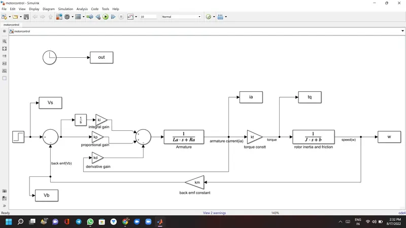
modelling
% motor parameters
J=0.85; % (kgm^2) moment of inertia of the rotor
b=0.1; % (Nms) motor viscous friction constant
km=0.01;% (v/rad/sec) back emf
kt=0.01;% (Nm/amp) motor torque constant
Ra=1;% (ohm) armature resistance
La=0.5;% (H) armature inductance
% equivalent wn
fn=1; %hz
wn=2*pi*fn; %rad/sec
% design parameters
zeta=0.9;% underdamped
% desired poles
p1=-zeta*wn-wn*sqrt(zeta^2-1);
p2=-zeta*wn+wn*sqrt(zeta^2-1);
P=[p1;p2];
% A & B matrices
A=[-b/J kt/J;-km/La -Ra/La];
B=[0;1/La];
c=[1 0];
D=0;
% poles placement design
K=place(A,B,P);
% gains
kp=38.3133;
kd=-2.8584;
ki=10;
plotting
subplot(321);plot(out,w,'r-');grid;
subplot(321);title('speed');
subplot(322);plot(out,tq,'m-');grid;title('torque');
subplot(323);plot(out,ia,'k-');grid;title('armature current');
subplot(324);plot(out,Vs),grid;title('supply voltage');
subplot(325);plot(out,Vb,'g');grid;title('back emf');
results
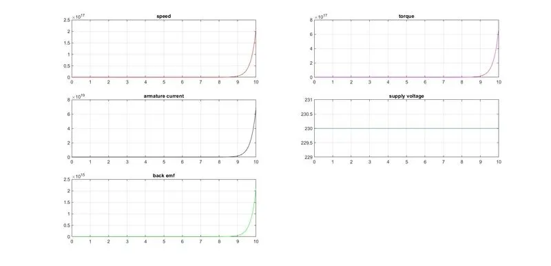
conclusion
speed of the dc motor has been maintained under different conditions.