MBD - Project on Vehicle Direction Detection
Aim - To create Vehicle Direction Detection Model accorging to the given requirements.
Objectives :-
- Development of MATLAB Simulink model as per requirement.
- Tagging the requirements to the simulink model; tagging requirement 1 & requirement 2 to their corresponding subsystems.
- MBD compliant changes, Data Dictionary creation & code generation.
- Explaination/Working of the Model
Overview :-
Identifying the direction of the vehicle is one of the important & diverse features in Autonomous driving & Advanced Driver Assistance Features. This particular sub-feature of identifying the direction of vehicle is basically identifying the direction the vehicle is taking based on the camera input.
Camera reads the road signs & stores into its memory with unique values for left turn, right turn & straight drive. Depending on the direction it is taking, final indication is given to the driver as an indication if he is driving in the recommended direction or not.
Vehicle Direction Determination can also be coupled along - side features like GPS systems to identify whether the vehicle is reaching its destination in an optimized manner. This sub feature can also be used along with Lane Detection, Highway Warning, Ramp Entry / Exit in Wrong Way Detection etc.
Model:-
Explaination of Model
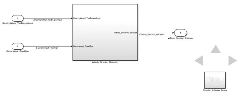
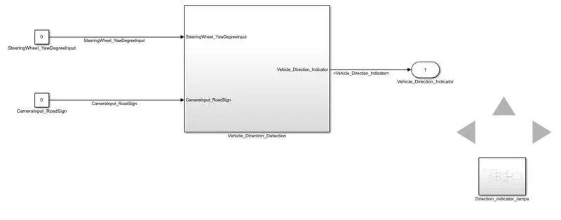
The function of the model is to take steering wheel yaw angle in degrees as input and accordingly give the indications to turn right, left or go straight. The model is build as per the requirements provided. An additional direction indicator lamp subsytem is added for better understanding of the model.
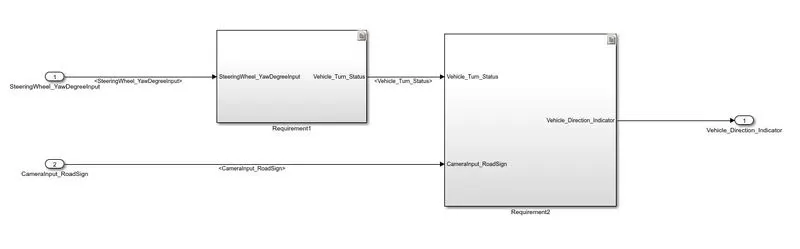
As we move inside the model, it is divided according to the 2 requirements.
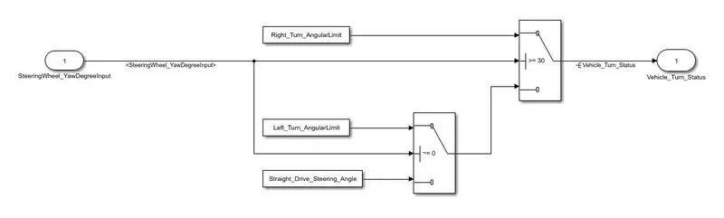
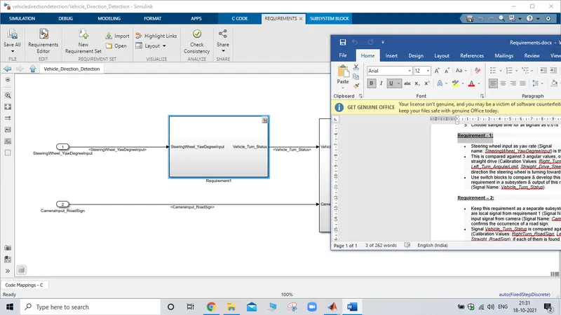
In Requirement1 subsystem the steering wheel yaw input is fed to 2 switch blocks which are connected to each other in such a way that if the input is from 30 to 180 then the vehicle turn status will be right. If the input is 0 then the vehicle turn status will be straight else for any other value than the above mentioned then vehicle turn status will be left.
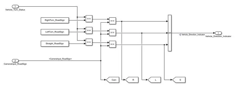
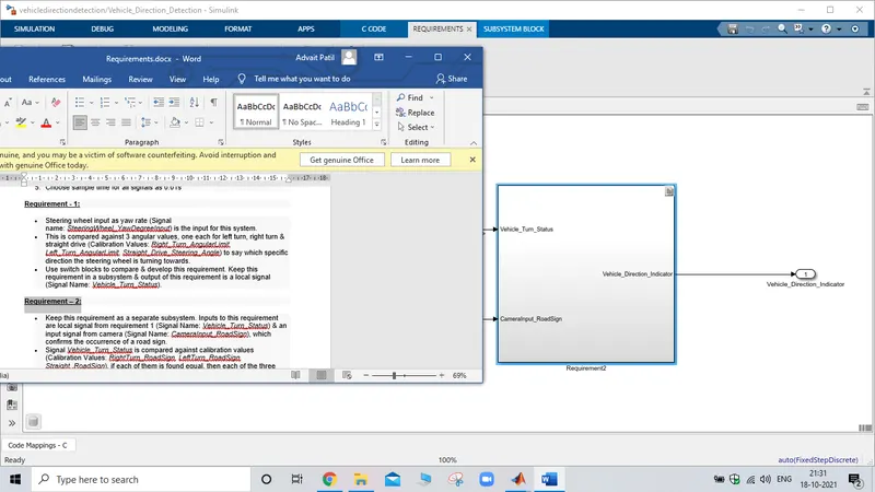
This output of Requirement1 subsystem is given as input to the Requirement2 subsystem. This input is comapred with the predefined values for right, left and straight road sign values. The second input given to this subsyatem is the camera input road sign. It is either one or zero. The compared values are then again compared with the camera input road sign value and a OR logic is taken for all the compared outputs. Since at a time any one of the value will be true the OR output will always be 1. Specifying that the Vehicle Direction Detection is on. However if The camera input road sign is not provided then Our system should not show any results.
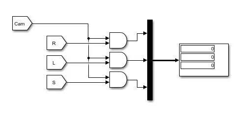
The extra subsystem named as the Direction_Indicator_Lamps is made using goto blocks and AND logic, it is not mandatory, it is added for better understanding of the model.
Results:-
When CameraInput_RoadSign is there and the SteeringWheel_YawDegreeInput is >=30 degrees.
The right indication lamp will glow.
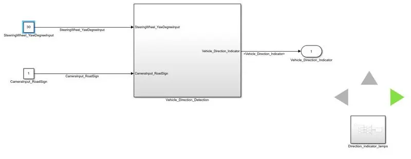
When CameraInput_RoadSign is there and the SteeringWheel_YawDegreeInput is ~=0 and is <30 degrees.
The left indication lamp will glow.
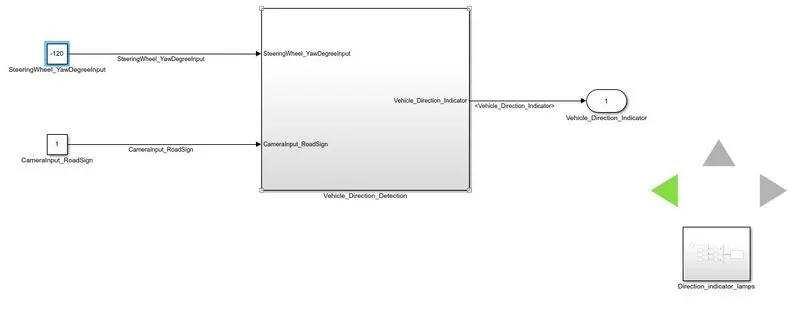
When CameraInput_RoadSign is there and the SteeringWheel_YawDegreeInput is = 0 degrees.
The straight indication lamp will glow.
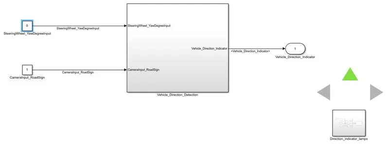
When CameraInput_RoadSign is not present so whatever SteeringWheel_YawDegreeInput is given
No indication lamp will glow.
Requirement Tagging
For requirement tagging we need to open the requirement document 1st. Then we need to select the requirement which needs to be tagged, then come to our model and select the specified requirement (block or subsystem). Right click on it under requirements option chose link to whichever format the requirement document is.
Requirement1
Requirement2
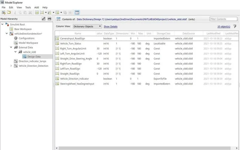
Simulink Data Dictionary
In this model all the variable values are defined in the simulink data dictionary not workspace. This simulink data dictionary is then linked to our model. This ensures that any pseudo value in the workspace will not interfere with out model as well as we can chose the data type of the signals, classify them as input, output, local, constants.
For creating SLDD, click on the modeling menu, here select the model properties option, in it click on external data or data. Here create a new sldd if required if already created then browse and link it to the model.
The sample time for all the signals is taken as 0.01 as per the requirement. This also done in the sldd.
Code Generation
For code generation in apps menu find for embedded coder. We first need to check for the configuartions.
Click on settings and under code generation make sure the target file selected is ert.tlc, if yes then we can move forward for code generation.
Click on the generate code option and a code will be generated.
Generated Code:-
/*
 * File: vehicledirectiondetection.c
 *
 * Code generated for Simulink model 'vehicledirectiondetection'.
 *
 * Model version                  : 1.9
 * Simulink Coder version         : 9.5 (R2021a) 14-Nov-2020
 * C/C++ source code generated on : Mon Oct 18 21:10:09 2021
 *
 * Target selection: ert.tlc
 * Embedded hardware selection: Intel->x86-64 (Windows64)
 * Code generation objectives: Unspecified
 * Validation result: Not run
 */

#include "vehicledirectiondetection.h"
#include "vehicledirectiondetection_private.h"

/* Real-time model */
static RT_MODEL_vehicledirectiondete_T vehicledirectiondetection_M_;
RT_MODEL_vehicledirectiondete_T *const vehicledirectiondetection_M =
  &vehicledirectiondetection_M_;

/* Model step function */
void vehicledirectiondetection_step(void)
{
  /* local block i/o variables */
  int16_T Vehicle_Turn_Status;

  /* Switch: '/Switch' incorporates:
   *  Inport: '/SteeringWheel_YawDegreeInput'
   *  Switch: '/Switch1'
   */
  if (SteeringWheel_YawDegreeInput >= Right_Turn_AngularLimit) {
    /* Switch: '/Switch' incorporates:
     *  Constant: '/Constant'
     */
    Vehicle_Turn_Status = Right_Turn_AngularLimit;
  } else if (SteeringWheel_YawDegreeInput != 0) {
    /* Switch: '/Switch1' incorporates:
     *  Constant: '/Constant1'
     *  Switch: '/Switch'
     */
    Vehicle_Turn_Status = Left_Turn_AngularLimit;
  } else {
    /* Switch: '/Switch' incorporates:
     *  Constant: '/Constant2'
     *  Switch: '/Switch1'
     */
    Vehicle_Turn_Status = Straight_Drive_Steering_Angle;
  }

  /* End of Switch: '/Switch' */

  /* Logic: '/OR' incorporates:
   *  Constant: '/Constant'
   *  Constant: '/Constant1'
   *  Constant: '/Constant2'
   *  Inport: '/CameraInput_RoadSign'
   *  RelationalOperator: '/Equal'
   *  RelationalOperator: '/Equal1'
   *  RelationalOperator: '/Equal2'
   *  RelationalOperator: '/Equal3'
   *  RelationalOperator: '/Equal4'
   *  RelationalOperator: '/Equal5'
   */
  Vehicle_Direction_Indicator = (((Vehicle_Turn_Status == RightTurn_RoadSign) ==
    (int32_T)CameraInput_RoadSign) || ((Vehicle_Turn_Status == LeftTurn_RoadSign)
    == (int32_T)CameraInput_RoadSign) || ((Vehicle_Turn_Status ==
    Straight_RoadSign) == (int32_T)CameraInput_RoadSign));
}

/* Model initialize function */
void vehicledirectiondetection_initialize(void)
{
  /* (no initialization code required) */
}

/* Model terminate function */
void vehicledirectiondetection_terminate(void)
{
  /* (no terminate code required) */
}

/*
 * File trailer for generated code.
 *
 * [EOF]
 */
MAAB Check
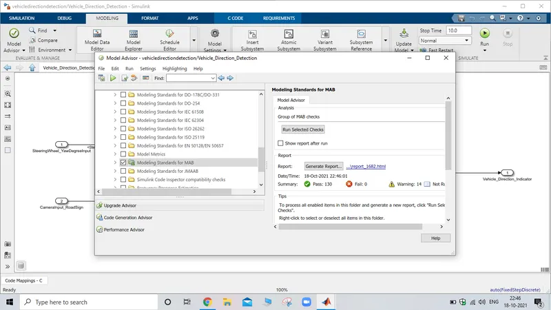
Since it is a MBD project, MAAB guideliness Check is essential.
For MAAB check we click on model advisor in that we select the MAAB check and run for checks. A report is generated in which we can see the errors and warinings. The errors must need to be resolved while if the warnings and the requirements are clashing then we can keep as it is
Conclusion:-
Hence we have developed a MATLAB Simulink model as per requirement.
All the requirement tagging is also done in the model.
We have created a data dictionary and the sample time for all the signals is taken as 0.01
Code for the model is also generated.
We have also check the modeling standards according to MAAB.