Plotting PV diagram of an Otto Cycle using MATLAB
Aim - To find the Thermal Efficiency of the engine and plot the PV diagram by solving an Otto Cycle.
About Otto Cycle :-
An Otto Cycle is an idealized thermodynamic cycle that describes the functioning of a typical spark ignition piston engine. Its a thermodynamic cycle most commonly found in automobile engines.
Basic terminologies of I.C. engine.
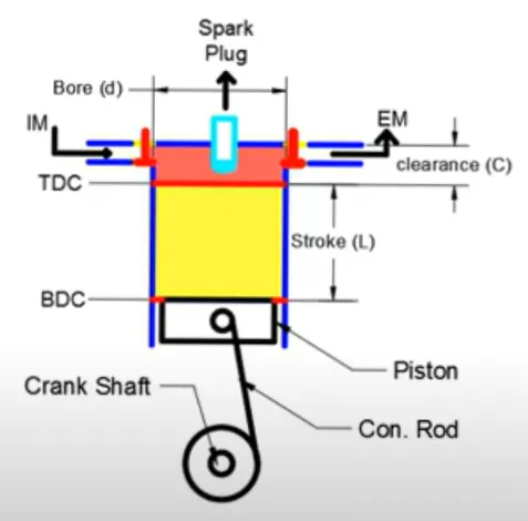
- Bore - The nominal inner diameter of cylinder is known as bore.
- TDC - Top Dead Centre, when piston is most away from the crank shaft.
- BDC - Bottom Dead Centre, when piston is closest to the crank shaft.
- Stroke - The nominal distance covered by the piston when it moves from BDC to TDC or TDC to BDC.
- Connecting Rod - The rod which connects the crank shaft and the piston is called the connecting rod.
- Swept Volume - It is the volume swept by the cylinder when the piston moves from TDC to BDC or the volume in the cylinder from TDC to BDC.
- Clearance Volume - The volume available in the cylinder when the piston is at TDC.
- Compression Ratio, CR - It is the ratio of total volume of cylinder to the clearance volume. It is always greater than 1.
- IM - Input Mixture, from where heat is transfered in the cylinder
- EM - Exhaust Mixture, from where the heat in the cylinder is removed.
Process of an Otto Cycle
The four-stroke Otto cycle is made up of the following four internally reversible processes:
Initially the piston can be at any position in its working space in the cylinder, a mass of air is drawn into piston/cylinder arrangement at constant pressure so that the piston moves to BDC.
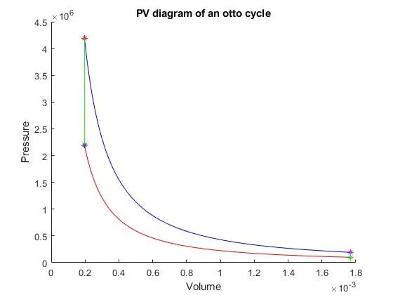
1–2, Isentropic Compression - The piston is at BDC, hence the initial volume is equal to the total volume. As the piston moves from BDC to TDC the gas is compressed and the volume changes. This change in volume ratio is known as the Compression Ratio. As this process is adiabatic and reversible also due to compression of gas taking place this process is known as isentropic compression.
2–3, Constant-volume heat addition - In this process the volume remains constant as the piston is rest at the TDC, meanwhile heat transfer takes place in the cylinder due to external source. Hence known as constant volume heat addition.
3–4, Isentropic Expansion - As heat is added to the cylinder the compressed gas expands resulting in the piston to move from TDC to BDC. The heat here does not leave the system yet making it an adiabatic and reversible also due to expansion of gas taking place this process is known as isentropic expansion.
4–1, Constant-volume heat rejection - In this process the volume remains constant as the piston is rest at the BDC, meanwhile heat rejection takes place in the cylinder. Hence known as constant volume heat rejection.
Formulas and equations used :-
Volume of a cylinder = `pi*r^2*h`
By using this formula we can calculate the Swept Volume, Vs =`(pi/4)*b^2*s`
By definition Compression Ratio, `cr= (Vs+Vc)/(Vc) ; Vc = (Vs)/(cr-1)`
Ideal gas law
- `P*V = n*R*T ; (P*V)/T= constant`
- `P*V^gamma = constant`
Change in volume inside the IC engine can be written as
`V/(Vc)= 1+1/2(cr-1)[R+1-cos(theta)-sqrt(R^2-sin^2(theta))]`
where 'R' is ratio of connecting rod to the crank pin radius (a)
where 'a' is the half of stroke
Thermal Efficiency of an IC engine can be written as,
`eta = (1-(1/(cr^(gamma-1))))*100`
Program to solve an Otto Cycle
% Code to solve an otto cyle

clear all
close all
clc

% Engine parameters
bore = 0.1;             % bore diameter
stroke = 0.2;           % stroke length
con_rod = 0.15;         % connecting rod length
cr = 9;                 % compression ratio
gamma = 1.4;            % specific heat ratio

% State variables at point 1
t1 = 500;
p1 = 101325;

% Calculating Swept Volume and Clearance Volume
% Swept_volume = Vs
% This is formula for volume of a cylinder, where bore is the inner
% diameter and stroke is the height; Vs = (pi/4)*bore^2*stroke
Vs = (pi/4)*bore^2*stroke;

% Clearance volume = Vc
% Compression Ratio, cr = (Vs+Vc)/Vc ; Vc = Vs/(cr-1)
Vc = Vs/(cr-1);

% Initially the piston is at bottom most position, hence volume v1 = Vs+Vc
v1 = Vs+Vc;

% State variables at point 2
% Here the piston moves to the top most position, hence volume v2 = Vc
v2 = Vc;
% Since it is an adiabatic process
% p1*v1^gamma = p2*v2^gamma ; p2 = p1*(v1/v2)^gamma
p2 = p1*(v1/v2)^gamma;
% By ideal gas law we can say PV = nRT ; p1*v1/t1 = p2*v2/t2
% t2 = p2*v2*t1/(p1*v1)
t2 = p2*v2*t1/(p1*v1);

% Change in volume and pressure from point 1 to 2 is the Volume compression
% & Pressure compression respectively
V_comp = change_in_volume(bore,stroke,cr,con_rod,180,0);
% Constant, C_comp = p1*v1^gamma
C_comp = p1*v1^gamma;
P_comp = C_comp./V_comp.^gamma;

% State variables at point 3
% Volume remains constant ; v2 = v3
v3 = v2;
t3 = 2300;
% By ideal gas law we can say PV = nRT ; p3*v3/t3 = p2*v2/t2
% p3 = p2*v2*t3/(v3*t2) ,since v2 = v3
p3 = p2*t3/t2;

% Change in volume and pressure from point 3 to 4 is the Volume expansion
% & Pressure expansion respectively
V_exp = change_in_volume(bore,stroke,cr,con_rod,0,180);
% Constant, C_exp = p3*v3^gamma
C_exp = p3*v3^gamma;
P_exp = C_exp./V_exp.^gamma;

% State variables at point 4
% Volume at point 4 is equal to volume at point 1 ; v4 = v1
v4 = v1;
% Since it is an adiabatic process
% p4*v4^gamma = p3*v3^gamma ; p4 = p3*(v3/v4)^gamma
p4 = p3*(v3/v4)^gamma;
% t4 = p4*v4*t3/(p3*v3)
t4 = p4*v4*t3/(p3*v3);

hold on
plot(v1, p1, '*','color','g')
plot(v2, p2, '*','color','b')
plot(v3, p3, '*','color','r')
plot(v4, p4, '*','color','m')
plot(V_comp,P_comp,'color','r')
plot(V_exp,P_exp,'color','b')
line([v1 v4],[p1 p4],'color','c')
line([v2 v3],[p2 p3],'color','g')

xlabel('Volume')
ylabel('Pressure')
title('PV diagram of an otto cycle')

% Thermal Effeciency of the engine, E
E = [1 - (1/(cr^(gamma-1)))]*100
The fuction named 'change_in_volume' is used in the above code
function [V] = change_in_volume(bore,stroke,cr,con_rod,start_crank,end_crank)

a = stroke/2;
R = con_rod/a;

% Swept Volume = Vs
Vs = pi/4*bore^2*stroke;
% Clearance Volume = Vc
Vc = Vs/(cr-1);

theta = linspace(start_crank,end_crank,100);

term1 = 0.5*(cr-1);
term2 = R+1-cosd(theta);
term3 = (R^2-sind(theta).^2).^0.5;

[V]= (1 + term1*(term2-term3))*Vc;

end
Outputs:
Explaination of Code:
Otto cycle is a complicated long process. Hence writing a code for the process makes it a lot easier to understand, compare, observe as well as to find specified answers. This process is similar to all types of IC engines, but all IC engines are not similar. They may have different geometric parameters and as well as the input provided to each engine may vary. Here the code comes handy in alot of ways.
The code is divided into 2 parts. One where we find all the state points and in other where we find the change in volume at compression and expansion
Just buy providing the geometric parameters like; bore, stroke, connecting rod length, compression ratio, starting crank angle and ending crank angle we can use a single code for different IC engines.
In an Otto cycle each state/point has 3 variables; Pressure, Volume and Temperature
In the first part of the code, by using the formulas and equations mention we find all the state variables. Initial pressure and temperature as well as the specific heat ratio (`gamma`) are provided and the volumes can be calculated from the geometric parameters of the engine. By finding all the variables of a state point we can find the variables of the next state point.
In the second part of the code just by providing the geometric parameters we can find the volume swept by the piston through the cycle. At compression the piston is at TDC hence the start crank angle is 180 and end crank angle is 0. At expansion the piston is at BDC hence the start crank angle is 0 and end crank angle is 180.
With the help of code we can plot the PV diagram of the otto cycle and can also find the thermal effenciency of the engine. This way we can find the working area of an engine, compare engines as well as tweak the parameters for a greater efficiency.
Errors faced and how they were fixed:
Incorrect use of '=' operator
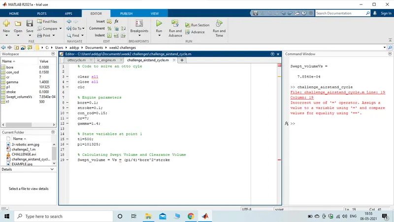
Fixed by using the '=' operator only one time in the equation
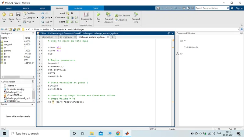
Error for using invalid color name/code
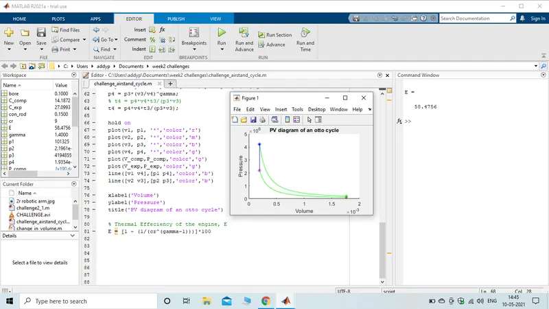
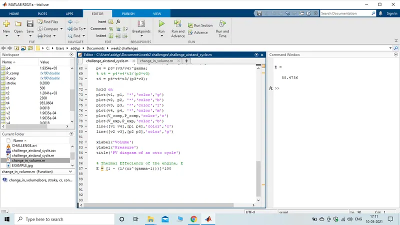
Results - The Thermal Efficiency of the IC engine is 58.47%
Conclusion - In this program we have calculated all the state points of the otto cycle process as well as plotted the PV diagram. The thermal efficiency of the engine is 58.47% and is a function of compression ratio and specific heat ratio. Since specific heat ratio is constant the efficiency can be increased by increasing the compression ratio.