Project 1 (Mini Project on Vehicle Direction Detection
Aim of the project :
Identifying the direction of the vehicle is one of the important & diverse features in Autonomous driving & Advanced Driver Assistance Features. This particular sub-feature of identifying the direction of vehicle is basically identifying the direction the vehicle is taking based on the camera input.
Camera reads the road signs & stores into its memory with unique values for left turn, right turn & straight drive. Depending on the direction it is taking, final indication is given to the driver – as an indication if he is driving in the recommended direction or not.
Description :
we have one input that is connected to the system that is "SteeringWheel_YawDegreeInput " signal according to the input the vehicle turn is decided like Left _turn , Right_Turn ,Straight_Drive .
The SteeringWheel_YawDegree Input is compared with the Left _turn , Right_Turn ,Straight_Drive to get the output of signal name "Vehicle _Turn _Status".
Then Vehicle_Turn_Status output signal is input as requirment -2.
Based on vehicle_turn_Status and camera_Input with these 2 inputs ,vehicle direction is decided.
SIMULINK MODEL:
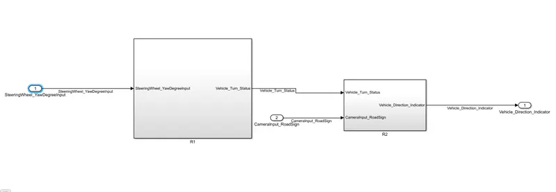
Requirement - 1:
- Steering wheel input as yaw rate (Signal name: SteeringWheel_YawDegreeInput) is the input for this system.
- This is compared against 3 angular values, one each for left turn, right turn & straight drive (Calibration Values: Right_Turn_AngularLimit, Left_Turn_AngularLimit, Straight_Drive_Steering_Angle) to say which specific direction the steering wheel is turning towards.
- Use switch blocks to compare & develop this requirement. Keep this requirement in a subsystem & output of this requirement is a local signal (Signal Name: Vehicle_Turn_Status).
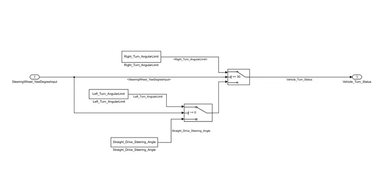
The logic in the Requirement_1 is, If the input is >=30 (because the initial value is 30) the vehicle will take the Right turn, else If the input is not-equal to zero (~=0) the vehicle left_turn, else stright_drive (if the input is equal to zero).
The input yaw rate is given to the middle port of the switch, and the threshold value is 30. If the input is greater than threshold value then the switch will takes the True condition (Right_Turn_AngularLimit) else false condition. In the second switch the threshold value is zero, if the threshold value is not equal to zero then the switch will takes the true condition (Left_Turn_AngularLimit) else takes the false condition (Sitight_Drive steering_Angle). This output from the second switch is given as a false condition to the first switch. And the output for the Requirement_1 is "Vehicle_Turn_Status".
Requirement – 2:
- Keep this requirement as a separate subsystem. Inputs to this requirement are local signal from requirement 1 (Signal Name: Vehicle_Turn_Status) & an input signal from camera (Signal Name: CameraInput_RoadSign), which confirms the occurrence of a road sign.
- Signal Vehicle_Turn_Signal is compared against calibration values (Calibration Values: RightTurn_RoadSign, LeftTurn_RoadSign, Straight_RoadSign), if each of them is found equal, then each of the three corresponding output is compared against the camera input signal,
- Using a logical operator block, only one among them is finally given as output signal (Signal Name: Vehicle_Direction_Indicator).
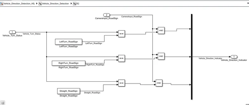
The logic in the Requirement_2 is to compare the "Vehicle_Turn_Status" (Output of Requirement_1) with "RoadSign" and an input signal from camera to get the Vehicle Direction indicaton.
After comparision with "Vehicle_Turn_Status" if each of them is found equal, then each of the three corresponding output is compared against the camera input signal, by using the 'logical AND' Blocks will get the true case.
And the final output from the Vehicle_Detection Model will indicates the vehicle_Direction indication.
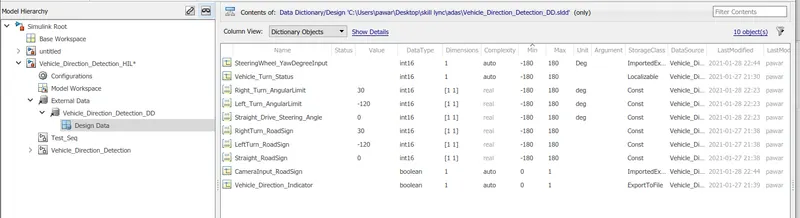
Next by adding the SLDD_file to the model and by loading the calibration values and input/output values are defined.
By running the simulation will get the vehicle direction.
SLDD:
Conclusion:
Autonomous vehicles consists of various Advance Driver-Assistance System (ADAS) features. Vehicle Driection Detection is one the features of the vehicles.
Hence, created an Simulink model of Vehicle Direction Detection as per the Requirement data.