Project 1 (Mini Project on Vehicle Direction Detection
Mini Project
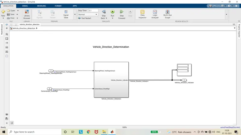
Vehicle Direction Determination
Aim:
To develop the Simulink model for the vehicle direction detection as per the given requirements and to tag the requirements to the Simulink model.
Given requirements:
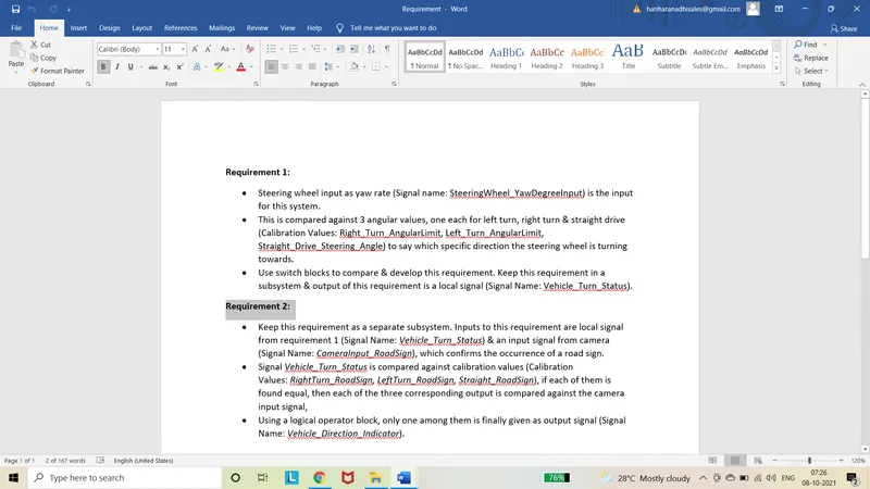
Requirement 1:
- Steering wheel input as yaw rate (Signal name: SteeringWheel_YawDegreeInput) is the input for this system.
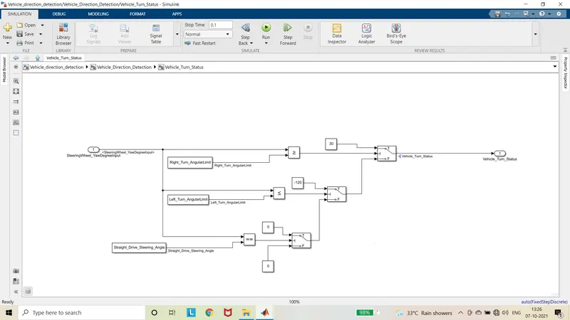
- This is compared against 3 angular values, one each for left turn, right turn & straight drive (Calibration Values: Right_Turn_AngularLimit, Left_Turn_AngularLimit, Straight_Drive_Steering_Angle) to say which specific direction the steering wheel is turning towards.
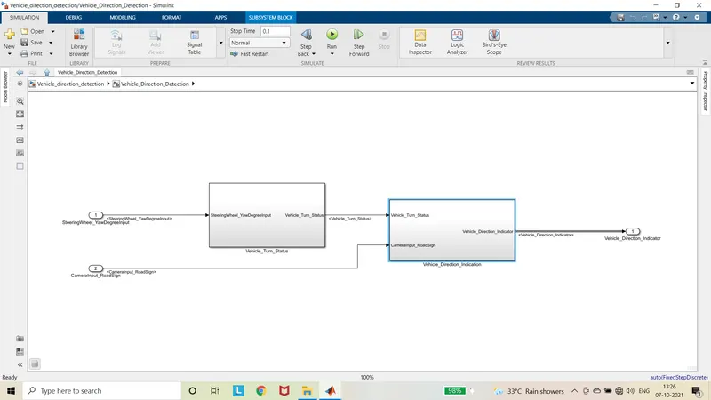
- Use switch blocks to compare & develop this requirement. Keep this requirement in a subsystem & output of this requirement is a local signal (Signal Name: Vehicle_Turn_Status).
Requirement 2:
- Keep this requirement as a separate subsystem. Inputs to this requirement are local signal from requirement 1 (Signal Name: Vehicle_Turn_Status) & an input signal from camera (Signal Name: CameraInput_RoadSign), which confirms the occurrence of a road sign.
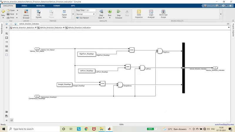
- Signal Vehicle_Turn_Statusis compared against calibration values (Calibration Values: RightTurn_RoadSign, LeftTurn_RoadSign, Straight_RoadSign), if each of them is found equal, then each of the three corresponding output is compared against the camera input signal,
- Using a logical operator block, only one among them is finally given as output signal (Signal Name: Vehicle_Direction_Indicator).
Model:
Procedure:
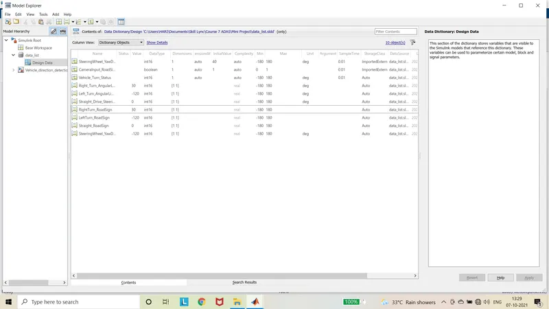
- In the modelling in Top pane select Link to data dictionary, and create a new file.
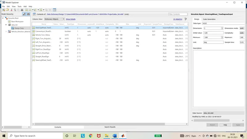
- Then the signals and calibration values are added according to the given specification.
- By right clicking the signal and in properties, check signal must resolve to Simulink signal object.
- According to the given requirement 1, the input is the Steering wheel angles as Yaw degree which ranges from -180 degree to 180 degree.
- This input is compared with the right turn angular limit that is 30.
- If the input is greater than or equal to 30, then the it gives the 30 as output.
- Else the input is compared with left turn angular limit which is -120.
- If the input is less than or equal to -120, then it gives -120 as output through the switch.
- Else the input is compared with Straight drive steering angle which is 0.
- If the input is equal to 0 then it gives 0 as output which gives the vehicle turn status.
- The above all are made into one subsystem.
- According to the given requirement 2, the input is the output from the above subsystem and camera input road sign.
- If The vehicle turn status is equal to Right turn Road sign value which is sensed and stored by camera then it is compared with camera input road sign when it is On or Off.
- If the vehicle turn status is equal to right turn road sign value and camera input road sign is On. Then it gives vehicle detection indicator to the driver.
- Here right turn indicator is given to the driver.
- If the vehicle turn status is equal to Left turn Road sign value, then it is compared with camera input road sign.
- If conditions are true, then it gives left turn indicator to driver.
- If the vehicle turn status is equal to Straight drive Road sign value, then it is compared with camera input road sign.
- If conditions are true, then it gives straight indicator to driver.
- If there is no signal from the camera, then no indicator turns On, because there is no road sign is sensed by camera.
- So, according to the given inputs the corresponding indicator turns on.
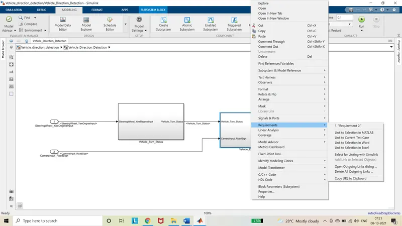
- By adding the requirements to the word file and by keeping it open and select the words in the word file and then in the Simulink model right clicking the required block or subsystem to be tagged and then in requirements select link to Selection in Word.
Output:
- If the input signal values, steering wheel yaw degree input is given as 40 and camera input road sign is given as 1, then it gives right turn indicator which is displayed as 1 0 0.
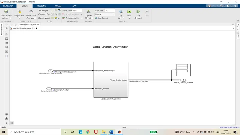
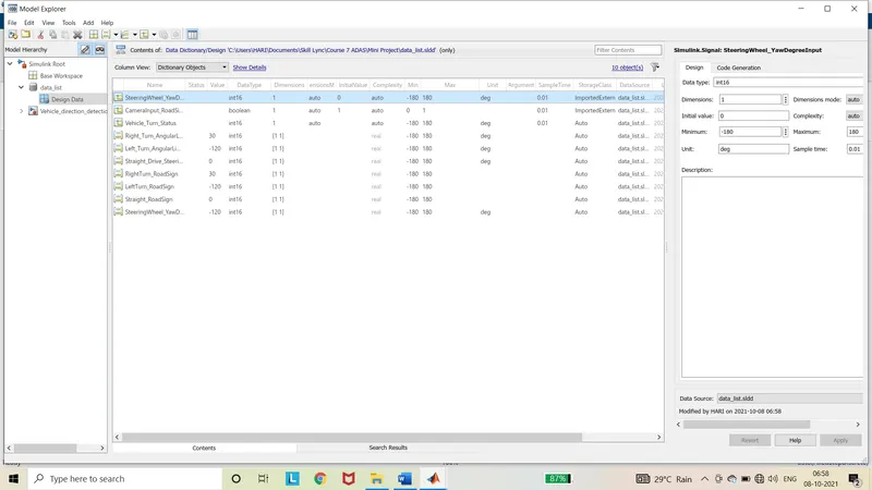
- If the steering wheel yaw degree input is given as -120 and camera input road sign is given as 1, then it gives left turn indicator which is displayed as 0 1 0.
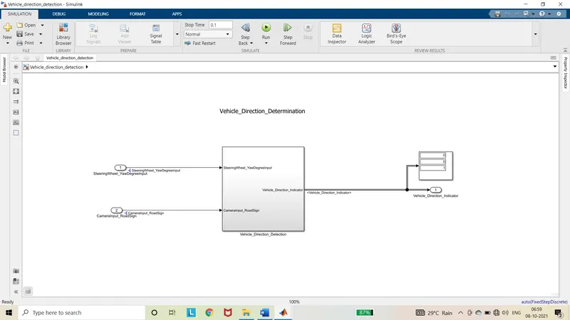
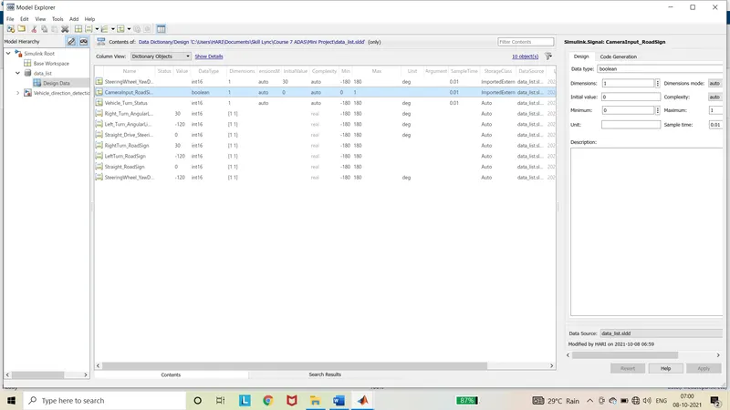
- If the steering wheel yaw degree input is given as 0 and camera input road sign is given as 1, then it gives left turn indicator which is displayed as 0 0 1.
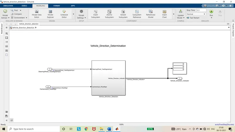
- If the camera input road sign is given as 0, then no indicator turn on which is displayed as 0 0 0.