Project 1 (Mini Project on Vehicle Direction Detection
Overview for this project:
Identifying the direction of the vehicle is one of the important & diverse features in Autonomous driving & Advanced Driver Assistance Features. This particular sub-feature of identifying the direction of vehicle is basically identifying the direction the vehicle is taking based on the camera input.
Camera reads the road signs & stores into its memory with unique values for left turn, right turn & straight drive. Depending on the direction it is taking, final indication is given to the driver – as an indication if he is driving in the recommended direction or not.
Vehicle Direction Determination can also be coupled along - side features like GPS systems to identify whether the vehicle is reaching its destination in an optimized manner. This sub feature can also be used along with Lane Detection, Highway Warning, Ramp Entry / Exit in Wrong Way Detection etc.
SLDD CREATION
-
The SLDD data files are related to the MATLAB/Simulink. Mathworks Simulink is a multidomain simulation and Model-Based Design for dynamic systems. The SLDD file stores some kind of data used by MATLAB. The following procedure shows how to create and add data to the SLDD file.
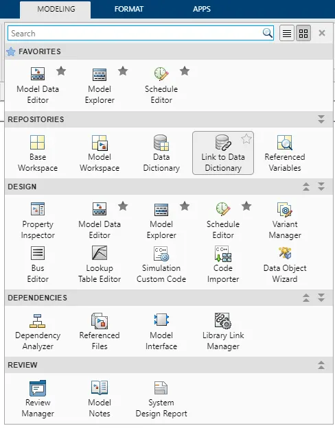
- To create a SLDD file, Open the simulink model and go to Modeling section.
- Then select Link to Data Dictionary option from Modeling section. Which is shown in the following figure.
-
After clicking on the Link to Data Dictionary, the following popup window will appears which ask us about data dictionary. If already created and to open SLDD, click on browse option and then select the respective file then click on ok. Here we are creating the new SLDD file so,
- Click on New and then save with a name. After saving the new SLDD file, uncheck the enable model access to base workspace because as it is new file there is no data to add workspace. If it is already created one then we can click on enable model access to base workspace.
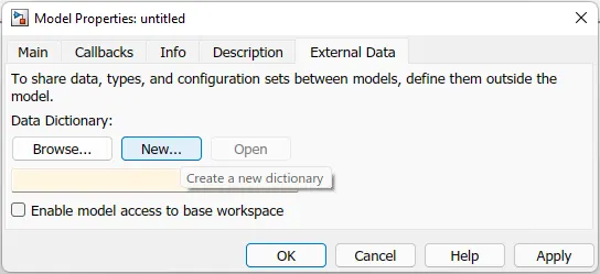
After saving the file the above popup window will closes.
- To open the SLDD file go to the Modeling section and then select Model explorer. Which is showing in the following figure.
-
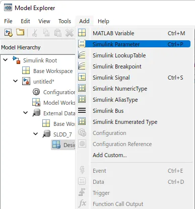
If we see at the top left side of the window, there are few option like file, edit, view, tools, add and help. If we click on add button it will show some options as shown in the following figure.
- From the options we can select our variable according to its natuure.
- If it is a signal then will select simulink signal if it is constant will select simulink parameter like that.
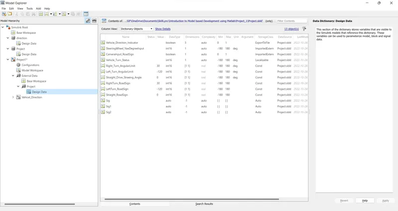
Now enter all signals and parameters according to the given signals and calibration data

After clicking on the Model explorer, the following window will opens. Where we can see our created SLDD file at left side of the window if we extend that will be able to see Design Data. By clicking on that we can add our given signals or parameters.
- I have given the name as "Project.sldd" which is shown in the figure and the datas are entered also
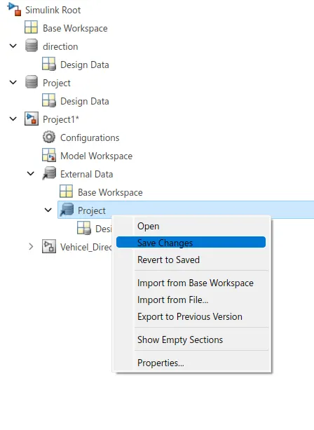
- Save the slld file shown is above figure and close the model explorer.
Model
- Create a subsystem in the name of "Vehicle_Direction" which as 2 inport and 1 outport
-
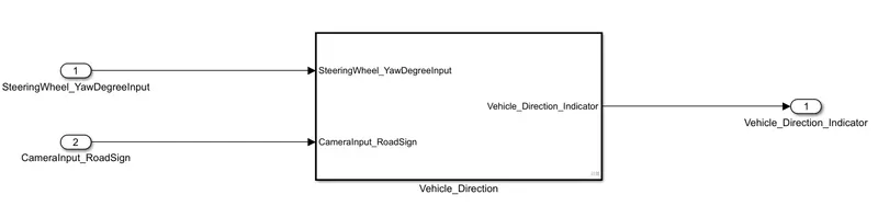
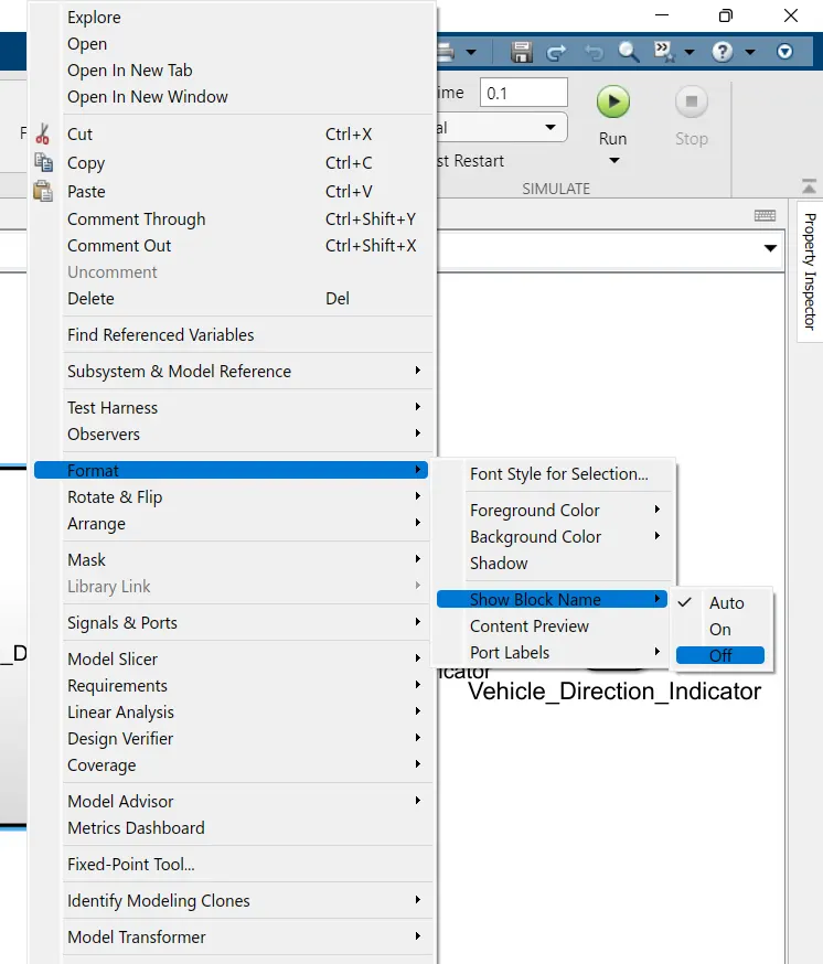
- Name the ports as shown in figure and make the block name as off
- Subsystem
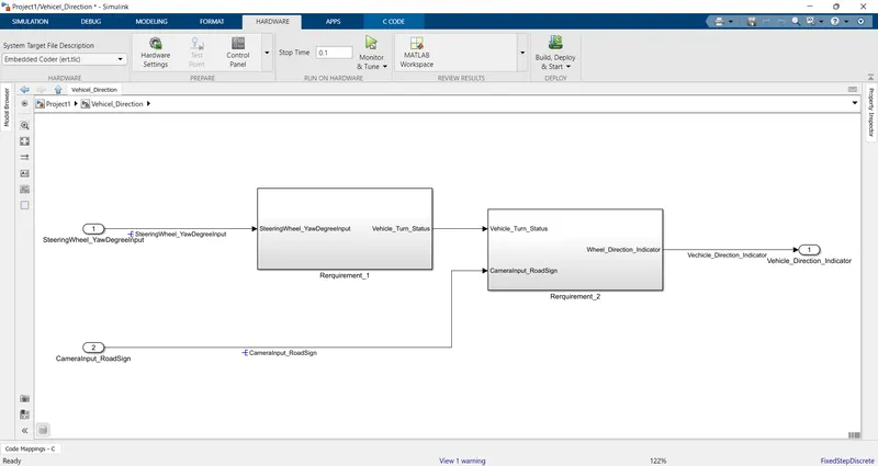
- Inside the subsytem create two subsytem which is named as "Requirement_1" & "Requirement_2" and hide the block content.
- Requirement_1
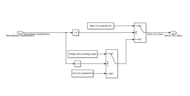
- Steering wheel input as yaw rate (Signal name: SteeringWheel_YawDegreeInput) is the input for this system.
- This is compared against 3 angular values, one each for left turn, right turn & straight drive (Calibration Values: Right_Turn_AngularLimit, Left_Turn_AngularLimit, Straight_Drive_Steering_Angle) to say which specific direction the steering wheel is turning towards.
- Use switch blocks to compare & develop this requirement. Keep this requirement in a subsystem & output of this requirement is a local signal (Signal Name: Vehicle_Turn_Status).
- Requirement_2
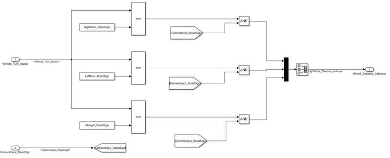
- Keep this requirement as a separate subsystem. Inputs to this requirement are local signal from requirement 1 (Signal Name: Vehicle_Turn_Status) & an input signal from camera (Signal Name: CameraInput_RoadSign), which confirms the occurrence of a road sign.
- Signal Vehicle_Turn_Status is compared against calibration values (Calibration Values: RightTurn_RoadSign, LeftTurn_RoadSign, Straight_RoadSign), if each of them is found equal, then each of the three corresponding output is compared against the camera input signal,
- Using a logical operator block, only one among them is finally given as output signal (Signal Name: Vehicle_Direction_Indicator).
- Tagging the model
- Tagging enables us to view the procedure which is used to build the model or to know more details about the designed model.
- First create the word file in the same folder.
- Select the respective header in the word file \
- In my case i selected the "Requirement_1" as an header
- Select the respective header in the word file \
- before tagging open the word file select the word which is used for tagging
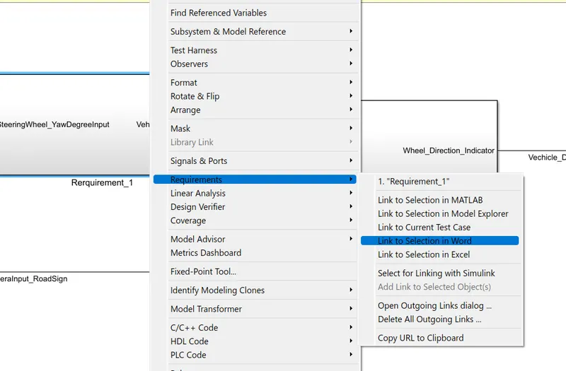
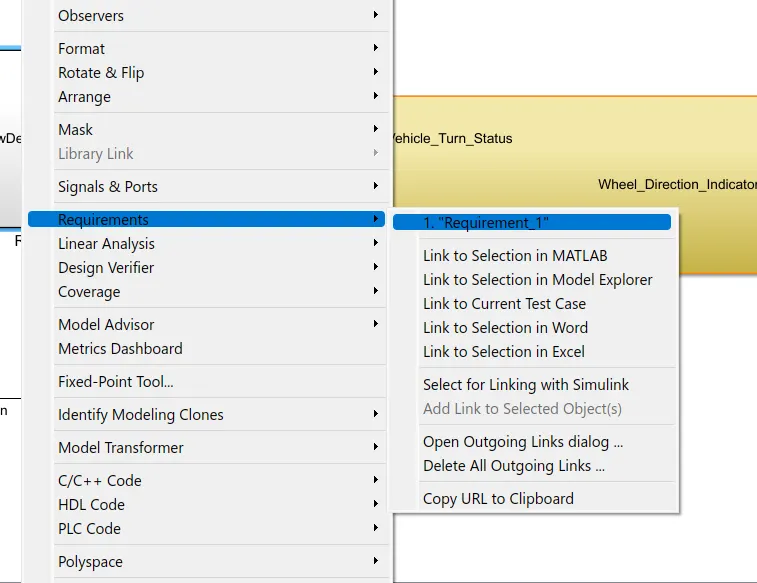
- To tagg the subsystem reffer the below figure
- Now will be able to see the tagging. Repeat same procedure like right click on subsystem go to requirements and from the options, the top 1. represents the word which is tagged to the subsystem.
- To know about the subsystem select the option displayed on the first
- Solver Settings
-
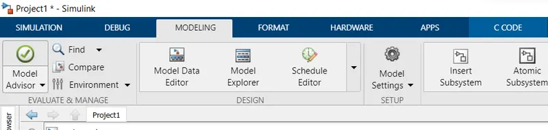
To open the solver setings, go to the Modeling section which is at the top of simulink window. And select the Model settings under the modeling section. Which is shown in the following figure

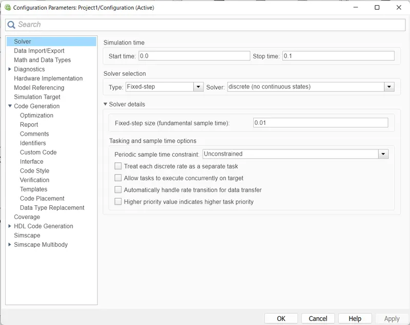
- In the configuration window, click on solver to model the solver parameters.
- Now change the type to Fixed-step, Solver to discrete(no continuous states) and take sample time as 0.01sec. Then click Ok.
- which is shown in th below figure
-
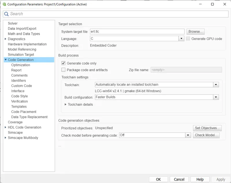
- Then goto the Code generation tab
- Choose the system targer file as ert.tlc (Embedded coder) by clicking on the browse option.
- Then click on Ok and close the window.
-
- MAB Guidelines
- To perform the MAB guidelines test on our simulink model, go to modeling section and select Model Advisor which is at the top left corner of the window.
- You can use the Model Advisor to verify compliance of your model with the MathWorks Advisory Board (MAB) guidelines.
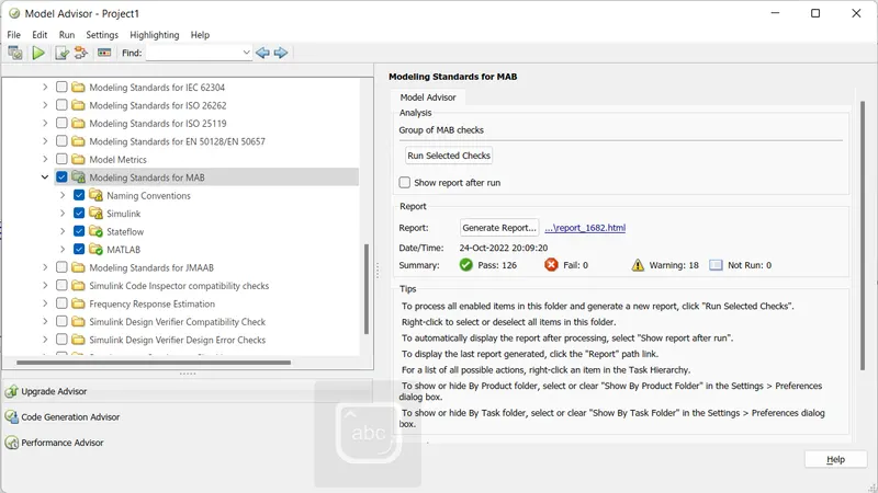
- In the Model advisor there are number of guidelines, among them will select only Modeling Standards fro MAB.
- If we expand the section will be able to see which are tested under the MAB guidelins. If we again expand there will be many sub sections in each section.
- After selecting MAB guidelines, click on Run Selected checks.
- Then it asks again for confirmation, click on continue. Then the testing will begins. It takes time to perform the guidelines test.
-
After the MAB guidelined test completion, it should be mandatory that 0 fail conditions. If any fail conditions are there rectify them and again make them to 0. The warnings are permittable to some limit.After getting 0 fails click on Generate report. This report will gives all data about the smulink model we have created.
-
- The report shows all the checks performed under MAB guidelines.
After clicking Generate report in the above window, a popup window will appears as shown in the followinng figure.
- It shows the directory, at where the report is going to save. It will save in the same folder of our simulink model.
- Give a name to the report. Then click on OK.
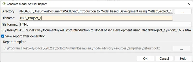
After clicking on Ok. It will save in the folder and opens as shown in the followig diagram.
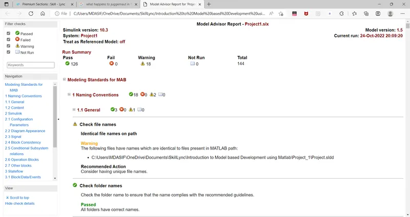
- The report shows all the checks performed under MAB guidelines.
- C-Coding
- Now we are converting all our model in terms of C Code. To create C code of our simulink model.
- Go to the Apps section which is at top of the window.
- Under Apps section, click on Embedder coder which is shown in the followinng figure

- Select the Embedded coder,
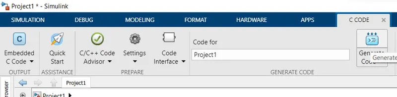
- The C code shows all the data of our simulink model. The C code file is also saved in the same folder of our simulink model.
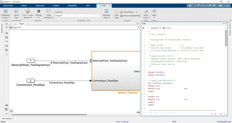
- Code
-
/* * File: Project1.c * * Code generated for Simulink model 'Project1'. * * Model version : 1.5 * Simulink Coder version : 9.5 (R2021a) 14-Nov-2020 * C/C++ source code generated on : Mon Oct 24 21:19:47 2022 * * Target selection: ert.tlc * Embedded hardware selection: Intel->x86-64 (Windows64) * Code generation objectives: Unspecified * Validation result: Not run */ #include "Project1.h" #include "Project1_private.h" /* Exported data definition */ /* Definition for custom storage class: ExportToFile */ boolean_T Vehicle_Direction_Indicator[3];/* '<S3>/Signal Conversion' */ /* Const memory section */ /* Definition for custom storage class: Const */ const int16_T LeftTurn_RoadSign = -120;/* Referenced by: '<S3>/Constant1' */ const int16_T Left_Turn_AngularLimit = -120;/* Referenced by: '<S2>/Constant1' */ const int16_T RightTurn_RoadSign = 30; /* Referenced by: '<S3>/Constant' */ const int16_T Right_Turn_AngularLimit = 30;/* Referenced by: '<S2>/Constant' */ const int16_T Straight_Drive_Streeing_Angle = 0;/* Referenced by: '<S2>/Constant2' */ const int16_T Straight_RoadSign = 0; /* Referenced by: '<S3>/Constant2' */ /* Real-time model */ static RT_MODEL_Project1_T Project1_M_; RT_MODEL_Project1_T *const Project1_M = &Project1_M_; /* Model step function */ void Project1_step(void) { int16_T rtb_Vehicle_Turn_Status; /* Outputs for Atomic SubSystem: '<Root>/Vehicel_Direction' */ /* Switch: '<S2>/Switch' incorporates: * Constant: '<S2>/Constant' * Constant: '<S2>/Constant1' * Constant: '<S4>/Constant' * Constant: '<S5>/Constant' * Inport: '<Root>/SteeringWheel_YawDegreeInput' * RelationalOperator: '<S4>/Compare' * RelationalOperator: '<S5>/Compare' * Switch: '<S2>/Switch1' */ if (SteeringWheel_YawDegreeInput > 0) { rtb_Vehicle_Turn_Status = Right_Turn_AngularLimit; } else if (SteeringWheel_YawDegreeInput == 0) { /* Switch: '<S2>/Switch1' incorporates: * Constant: '<S2>/Constant2' */ rtb_Vehicle_Turn_Status = Straight_Drive_Streeing_Angle; } else { rtb_Vehicle_Turn_Status = Left_Turn_AngularLimit; } /* End of Switch: '<S2>/Switch' */ /* SignalConversion: '<S3>/Signal Conversion' incorporates: * Constant: '<S3>/Constant' * Constant: '<S3>/Constant1' * Constant: '<S3>/Constant2' * Inport: '<Root>/CameraInput_RoadSign' * Logic: '<S3>/AND' * Logic: '<S3>/AND1' * Logic: '<S3>/AND2' * RelationalOperator: '<S3>/Relational Operator' * RelationalOperator: '<S3>/Relational Operator1' * RelationalOperator: '<S3>/Relational Operator2' */ Vehicle_Direction_Indicator[0] = ((rtb_Vehicle_Turn_Status == RightTurn_RoadSign) && CameraInput_RoadSign); Vehicle_Direction_Indicator[1] = ((rtb_Vehicle_Turn_Status == LeftTurn_RoadSign) && CameraInput_RoadSign); Vehicle_Direction_Indicator[2] = ((rtb_Vehicle_Turn_Status == Straight_RoadSign) && CameraInput_RoadSign); /* End of Outputs for SubSystem: '<Root>/Vehicel_Direction' */ } /* Model initialize function */ void Project1_initialize(void) { /* (no initialization code required) */ } /* Model terminate function */ void Project1_terminate(void) { /* (no terminate code required) */ } /* * File trailer for generated code. * * [EOF] */ - Test
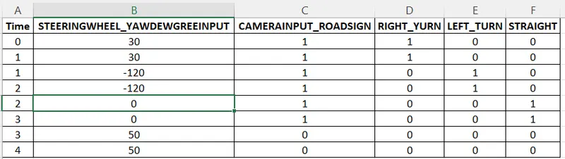
- To perform any test case like MIL and SIL, first we have to develop an excel sheet which represents the inputs according to their outputs.
- Here input represents the Steeringwheel_yaw degreeinput values.
- And the respective directions according to thecamerainput_roadsign, outputs are taken. Which are considered by using the minimum and maximum values given in the table.
- The following figure shows the excel sheet we have created with the given input with the possible output. Save the excel sheet in the same folder of simulink model.
- MIL Test
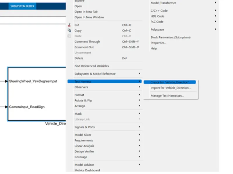
- To perform MIL test, right click on the Vehicle_Direction subsystem and select Test harness from the context. And then select Create for Vehicle_Direction.
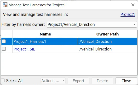
- Here i had created 2 test harness cases which is Project1_harrness1 for MIL testing and Project1_SIL for SIL testing.
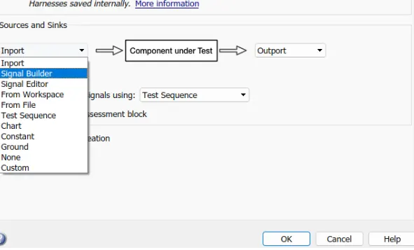
- Select inport as Signal Builder under source and sinks.
-
In the same window go to advanced properties and select the verification mode as Normal as shown in the following figure. After selecting the verification mode click on OK.
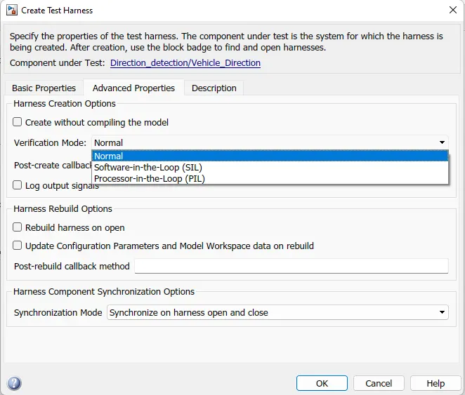
- After clicking on Ok in the above create test harness window. A simulink window will opens with the test harness model. Which is connected with the signal builder at the input side, as we selected in the create test harness window.
-

Now we have to add the excel sheet we have created to perform the MIL test of our simulink model to signal builder.
- To import the file, double click on the Signal builder block. Select import from file option from the File section. Which is shown in the following figure.
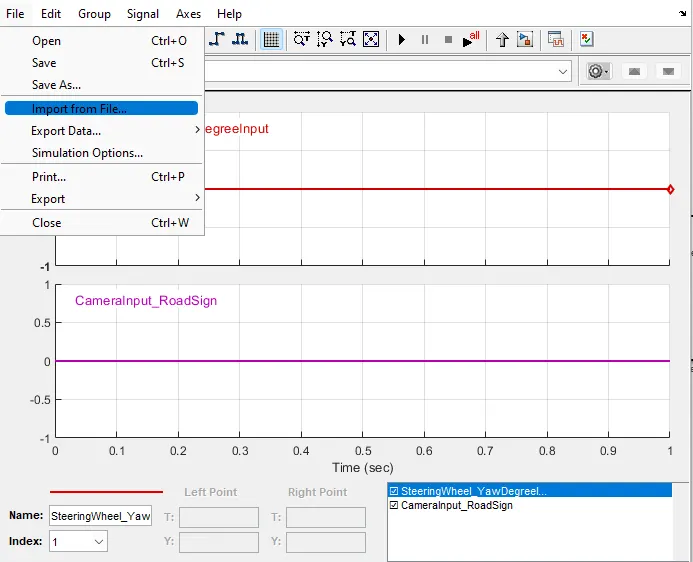
Then the following window will appears. By clicking on the browse option will be able to select the file we have saved. By selecting the file it will appears at 'data to import' section.
-
Click on select all, and select replace existing data from the placement for selected data. Then click on confirm selection and then click on Ok.
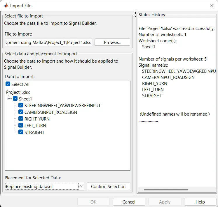
-
After the above procedure, the respective signals will be added to the signal builder block as shown in the following figure.
- Where the first plot and second plot shows the input signal, third plot one shows Right Turn, 4th one shows Left Turn data and %th plot shows stright way data. As we have created the excel sheet in the form of step wave, here we are seeing the step waveform.
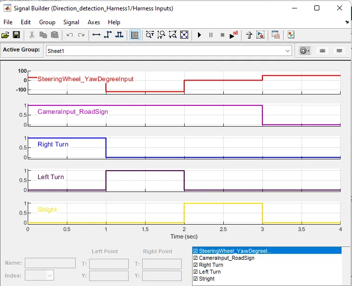
- The following plot will appear in the signal builder
- Then connect the three sum block, de-mux block and the scope block as per shown in fig
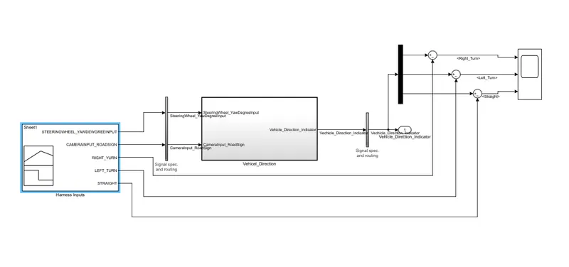
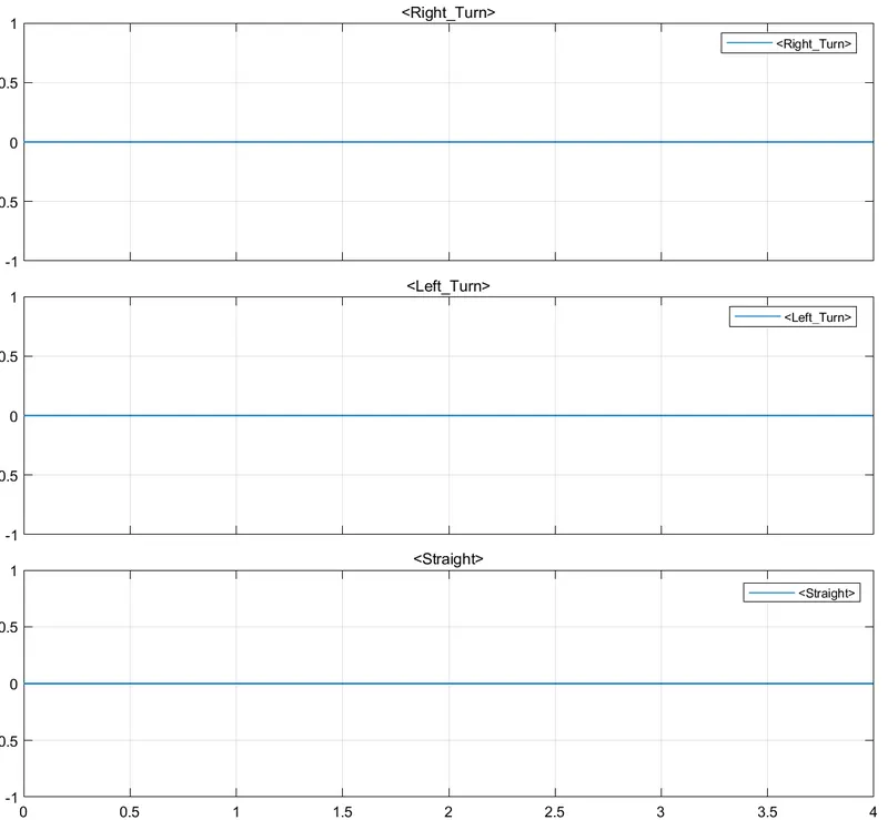
- Run the test harness for 4 seconds Where the output of the scope shows constant 0 signal. Which means our given outputs and actual outputs are matched and cancelled each other. There are no errors in the model.
- SIL Testing
- The MIL test and SIL tests are almost same in procedure of performing the test. The difference is to select the atomic unit. Which is selected through the following procedure.
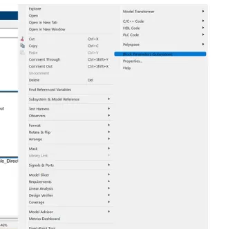
- Right click on the subsystem and then select Block parameters(subsystem) from the context.
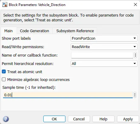
- Where we have tick the option 'Treat as atomic unit'. And give sample time as given in solver settings. As we have given 0.01sec in solver here also giving the same sampling time.
- The same procedure is used for SIL like MIL
- Where create test harness in my case i named as Project1_SIL
- In the same window go to advanced properties and select the verification mode as Software-in-the-Loop(SIL) as shown in the following figure. After selecting the verification mode click on OK.
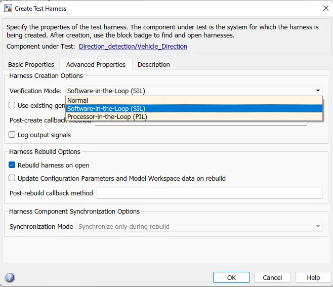
- After clicking on Ok in the above create test harness window. A simulink window will opens with the test harness model. Which is connected with the signal builder at the input side, as we selected in the create test harness window.
-
Now we have to add the excel sheet we have created to perform the MIL test of our simulink model to signal builder.
- To import the file, double click on the Signal builder block. Select import from file option from the File section. Which is shown in the following figure.
Then the following window will appears. By clicking on the browse option will be able to select the file we have saved. By selecting the file it will appears at 'data to import' section.
-
Click on select all, and select replace existing data from the placement for selected data. Then click on confirm selection and then click on Ok.
-
After the above procedure, the respective signals will be added to the signal builder block as shown in the following figure.
- Where the first plot and second plot shows the input signal, third plot one shows Right Turn, 4th one shows Left Turn data and %th plot shows stright way data. As we have created the excel sheet in the form of step wave, here we are seeing the step waveform.
- The following plot will appear in the signal builder
- Then connect the three sum block, de-mux block and the scope block as per shown in fig
- Run the test harness for 4 seconds Where the output of the scope shows constant 0 signal. Which means our given outputs and actual outputs are matched and cancelled each other. There are no errors in the model.
- Result
- The Vehicle Direction Detection is modeled as per the given requirements, all the signals and calibrated values are defined in the Simulink Data Dictionary(SLDD).
- All input and output signals are resolved and propagated.
- Model Advisory check is done with MAB guidelines and there is 0 fail conditions.
- Since there are no errors in Model Advisory report C Code has been generated by using Embedded coder. MIL and SIL tests are also perfromed sucessfully.
-