Project 1 (Mini Project on Vehicle Direction Detection
MINI PROJECT: 1 :
OBJECTIVE :
- Development of MATLAB Simulink model as per requirement.
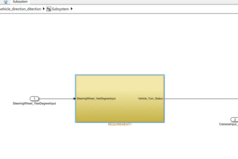
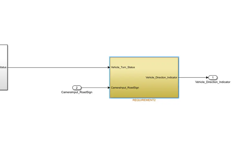
- Tag the requirements to the simulink model; tagging requirement 1 & requirement 2 to their corresponding subsystems is fine
REQUIREMENT: 1 :
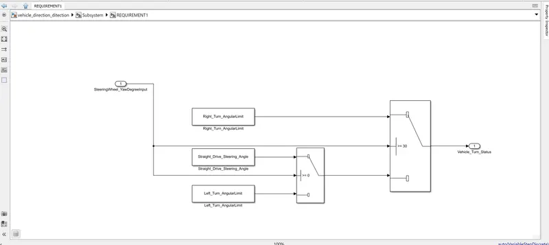
- Steering wheel input as yaw rate (Signal name: SteeringWheel_YawDegreeInput) is the input for this system.
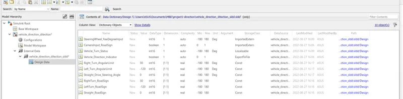
- This is compared against 3 angular values, one each for left turn, right turn & straight drive (Calibration Values: Right_Turn_AngularLimit, Left_Turn_AngularLimit, Straight_Drive_Steering_Angle) to say which specific direction the steering wheel is turning towards.
- Use switch blocks to compare & develop this requirement. Keep this requirement in a subsystem & output of this requirement is a local signal (Signal Name: Vehicle_Turn_Status).
REQUIREMENT: 2 :
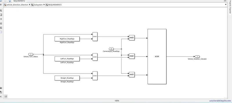
- Keep this requirement as a separate subsystem. Inputs to this requirement are local signal from requirement 1 (Signal Name: Vehicle_Turn_Status) & an input signal from camera (Signal Name: CameraInput_RoadSign), which confirms the occurrence of a road sign.
- Signal Vehicle_Turn_Status is compared against calibration values (Calibration Values: RightTurn_RoadSign, LeftTurn_RoadSign, Straight_RoadSign), if each of them is found equal, then each of the three corresponding output is compared against the camera input signal,
- Using a logical operator block, only one among them is finally given as output signal (Signal Name: Vehicle_Direction_Indicator).
PROCEDURE :
step:1: open a new simulink model.
step:2: analyse the requuirements
step:3: create the subsystem with 2 inputs and 1 output.
step:4: inside that subsystem create two more subsystem for requirement 1 & 2.
step:5: As per the requirement the switch block is used to compare the inputs with 3 other calibration values.
step:6: connect that output with the 2nd subsystem which is created for requirement 2 as a input(local).
step:7: using the logical operators the input is compared with 3 other callibration values.
step:8: These values are again compared with 2nd input.
step:9: As per the requirement single output is given out.
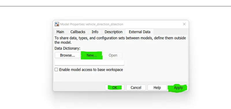
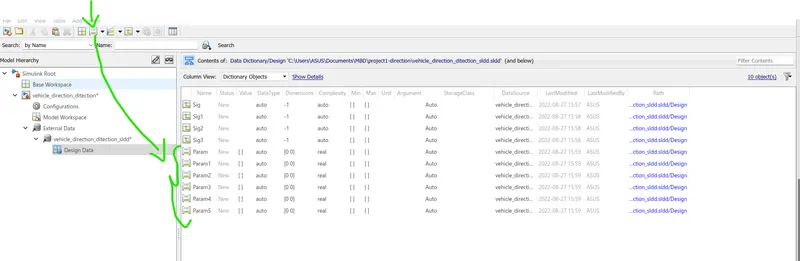
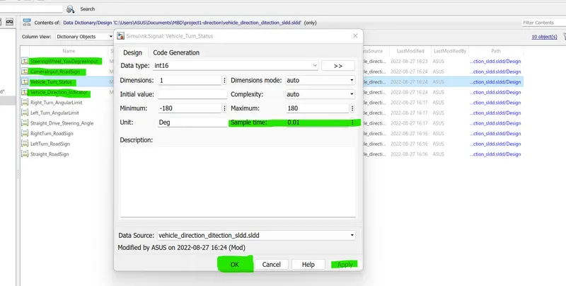
step:10:create the data dictionary for all the values.
step:11:By selecting the subsystem and right cllick>requirements and choose the option to add the requirements for both the subsystems.
step:12:In the modelling section the configuration parameters can changed from variable to fixed in solver and in code generation section embedded coder was selected.
step:13: finally using the build option the code was generated.
step:14:save the file.
SIMULINK BLOCKS: 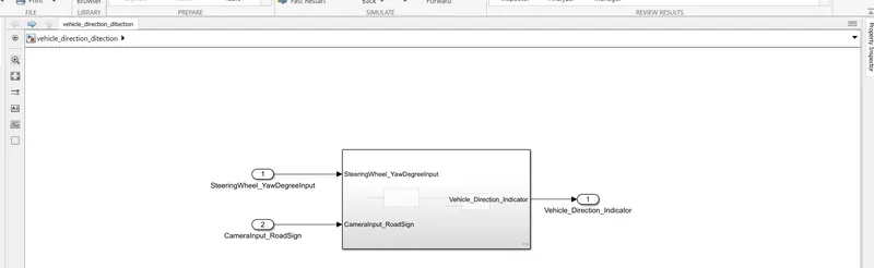
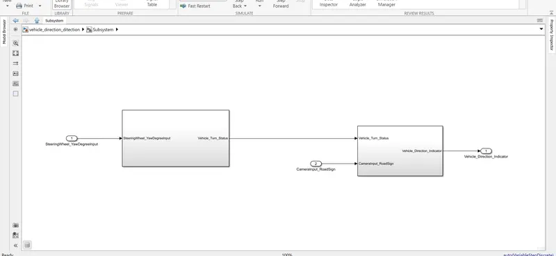
SIMULINK DATA DICTIONARY: 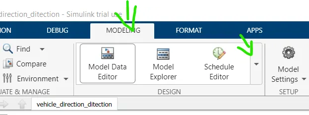
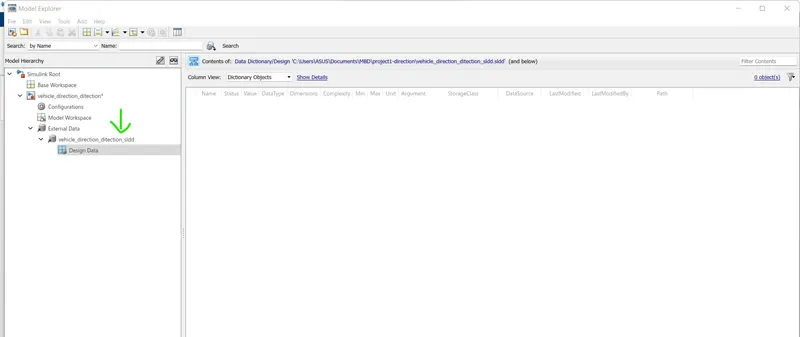
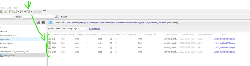
REQUIREMENT TAGGING:
CODE GENERATION :
ert_main.c
/*
 * File: ert_main.c
 *
 * Code generated for Simulink model 'vehicle_direction_ditection_'.
 *
 * Model version                  : 1.1
 * Simulink Coder version         : 9.5 (R2021a) 14-Nov-2020
 * C/C++ source code generated on : Sun Aug 28 17:07:34 2022
 *
 * Target selection: ert.tlc
 * Embedded hardware selection: Intel->x86-64 (Windows64)
 * Code generation objectives: Unspecified
 * Validation result: Not run
 */

#include <stddef.h>
#include <stdio.h>              /* This ert_main.c example uses printf/fflush */
#include "vehicle_direction_ditection_.h" /* Model's header file */
#include "rtwtypes.h"

/*
 * Associating rt_OneStep with a real-time clock or interrupt service routine
 * is what makes the generated code "real-time".  The function rt_OneStep is
 * always associated with the base rate of the model.  Subrates are managed
 * by the base rate from inside the generated code.  Enabling/disabling
 * interrupts and floating point context switches are target specific.  This
 * example code indicates where these should take place relative to executing
 * the generated code step function.  Overrun behavior should be tailored to
 * your application needs.  This example simply sets an error status in the
 * real-time model and returns from rt_OneStep.
 */
void rt_OneStep(void);
void rt_OneStep(void)
{
  static boolean_T OverrunFlag = false;

  /* Disable interrupts here */

  /* Check for overrun */
  if (OverrunFlag) {
    rtmSetErrorStatus(vehicle_direction_ditection__M, "Overrun");
    return;
  }

  OverrunFlag = true;

  /* Save FPU context here (if necessary) */
  /* Re-enable timer or interrupt here */
  /* Set model inputs here */

  /* Step the model */
  vehicle_direction_ditection__step();

  /* Get model outputs here */

  /* Indicate task complete */
  OverrunFlag = false;

  /* Disable interrupts here */
  /* Restore FPU context here (if necessary) */
  /* Enable interrupts here */
}

/*
 * The example "main" function illustrates what is required by your
 * application code to initialize, execute, and terminate the generated code.
 * Attaching rt_OneStep to a real-time clock is target specific.  This example
 * illustrates how you do this relative to initializing the model.
 */
int_T main(int_T argc, const char *argv[])
{
  /* Unused arguments */
  (void)(argc);
  (void)(argv);

  /* Initialize model */
  vehicle_direction_ditection__initialize();

  /* Attach rt_OneStep to a timer or interrupt service routine with
   * period 0.1 seconds (the model's base sample time) here.  The
   * call syntax for rt_OneStep is
   *
   *  rt_OneStep();
   */
  printf("Warning: The simulation will run forever. "
         "Generated ERT main won't simulate model step behavior. "
         "To change this behavior select the 'MAT-file logging' option.\n");
  fflush((NULL));
  while (rtmGetErrorStatus(vehicle_direction_ditection__M) == (NULL)) {
    /*  Perform other application tasks here */
  }

  /* Disable rt_OneStep() here */

  /* Terminate model */
  vehicle_direction_ditection__terminate();
  return 0;
}

/*
 * File trailer for generated code.
 *
 * [EOF]
 */
vehicle_direction_ditection.c
/*
 * File: vehicle_direction_ditection_.c
 *
 * Code generated for Simulink model 'vehicle_direction_ditection_'.
 *
 * Model version                  : 1.1
 * Simulink Coder version         : 9.5 (R2021a) 14-Nov-2020
 * C/C++ source code generated on : Sun Aug 28 17:07:34 2022
 *
 * Target selection: ert.tlc
 * Embedded hardware selection: Intel->x86-64 (Windows64)
 * Code generation objectives: Unspecified
 * Validation result: Not run
 */

#include "vehicle_direction_ditection_.h"
#include "vehicle_direction_ditection__private.h"

/* Exported data definition */

/* Const memory section */
/* Definition for custom storage class: Const */
const int16_T LeftTurn_RoadSign = -120;
                                   /* Referenced by: '<S3>/LeftTurn_RoadSign' */
const int16_T Left_Turn_AngularLimit = -120;
                              /* Referenced by: '<S2>/Left_Turn_AngularLimit' */
const int16_T RightTurn_RoadSign = 30;
                                  /* Referenced by: '<S3>/RightTurn_RoadSign' */
const int16_T Right_Turn_AngularLimit = 30;
                             /* Referenced by: '<S2>/Right_Turn_AngularLimit' */
const int16_T Straight_Drive_Steering_Angle = 0;
                       /* Referenced by: '<S2>/Straight_Drive_Steering_Angle' */
const int16_T Straight_RoadSign = 0;
                                   /* Referenced by: '<S3>/Straight_RoadSign' */

/* External inputs (root inport signals with default storage) */
ExtU_vehicle_direction_ditect_T vehicle_direction_ditection__U;

/* External outputs (root outports fed by signals with default storage) */
ExtY_vehicle_direction_ditect_T vehicle_direction_ditection__Y;

/* Real-time model */
static RT_MODEL_vehicle_direction_di_T vehicle_direction_ditection__M_;
RT_MODEL_vehicle_direction_di_T *const vehicle_direction_ditection__M =
  &vehicle_direction_ditection__M_;

/* Model step function */
void vehicle_direction_ditection__step(void)
{
  int16_T rtb_Switch;

  /* Switch: '<S2>/Switch' incorporates:
   *  Constant: '<S2>/Left_Turn_AngularLimit'
   *  Constant: '<S2>/Right_Turn_AngularLimit'
   *  Inport: '<Root>/SteeringWheel_YawDegreeInput  '
   *  Switch: '<S2>/Switch1'
   */
  if (vehicle_direction_ditection__U.SteeringWheel_YawDegreeInput >= 30.0) {
    rtb_Switch = Right_Turn_AngularLimit;
  } else if (vehicle_direction_ditection__U.SteeringWheel_YawDegreeInput >= 0.0)
  {
    /* Switch: '<S2>/Switch1' incorporates:
     *  Constant: '<S2>/Straight_Drive_Steering_Angle'
     */
    rtb_Switch = Straight_Drive_Steering_Angle;
  } else {
    rtb_Switch = Left_Turn_AngularLimit;
  }

  /* End of Switch: '<S2>/Switch' */

  /* Outport: '<Root>/Vehicle_Direction_Indicator' incorporates:
   *  Constant: '<S3>/LeftTurn_RoadSign'
   *  Constant: '<S3>/RightTurn_RoadSign'
   *  Constant: '<S3>/Straight_RoadSign'
   *  Inport: '<Root>/CameraInput_RoadSign'
   *  Logic: '<S3>/AND'
   *  Logic: '<S3>/AND1'
   *  Logic: '<S3>/AND2'
   *  Logic: '<S3>/OR'
   *  RelationalOperator: '<S3>/Equal'
   *  RelationalOperator: '<S3>/Equal1'
   *  RelationalOperator: '<S3>/Equal2'
   */
  vehicle_direction_ditection__Y.Vehicle_Direction_Indicator = (boolean_T)
    (((rtb_Switch == RightTurn_RoadSign) &&
      vehicle_direction_ditection__U.CameraInput_RoadSign) ^
     (vehicle_direction_ditection__U.CameraInput_RoadSign && (rtb_Switch ==
       LeftTurn_RoadSign
))) ^
    (vehicle_direction_ditection__U.CameraInput_RoadSign && (rtb_Switch ==
      Straight_RoadSign));
}

/* Model initialize function */
void vehicle_direction_ditection__initialize(void)
{
  /* (no initialization code required) */
}

/* Model terminate function */
void vehicle_direction_ditection__terminate(void)
{
  /* (no terminate code required) */
}

/*
 * File trailer for generated code.
 *
 * [EOF]
 */
vehicle_direction_ditection.h
/*
 * File: vehicle_direction_ditection_.h
 *
 * Code generated for Simulink model 'vehicle_direction_ditection_'.
 *
 * Model version                  : 1.1
 * Simulink Coder version         : 9.5 (R2021a) 14-Nov-2020
 * C/C++ source code generated on : Sun Aug 28 17:07:34 2022
 *
 * Target selection: ert.tlc
 * Embedded hardware selection: Intel->x86-64 (Windows64)
 * Code generation objectives: Unspecified
 * Validation result: Not run
 */

#ifndef RTW_HEADER_vehicle_direction_ditection__h_
#define RTW_HEADER_vehicle_direction_ditection__h_
#ifndef vehicle_direction_ditection__COMMON_INCLUDES_
#define vehicle_direction_ditection__COMMON_INCLUDES_
#include "rtwtypes.h"
#endif                       /* vehicle_direction_ditection__COMMON_INCLUDES_ */

#include "vehicle_direction_ditection__types.h"

/* Macros for accessing real-time model data structure */
#ifndef rtmGetErrorStatus
#define rtmGetErrorStatus(rtm)         ((rtm)->errorStatus)
#endif

#ifndef rtmSetErrorStatus
#define rtmSetErrorStatus(rtm, val)    ((rtm)->errorStatus = (val))
#endif

/* External inputs (root inport signals with default storage) */
typedef struct {
  real_T SteeringWheel_YawDegreeInput;
                                   /* '<Root>/SteeringWheel_YawDegreeInput  ' */
  boolean_T CameraInput_RoadSign;      /* '<Root>/CameraInput_RoadSign' */
} ExtU_vehicle_direction_ditect_T;

/* External outputs (root outports fed by signals with default storage) */
typedef struct {
  boolean_T Vehicle_Direction_Indicator;
                                      /* '<Root>/Vehicle_Direction_Indicator' */
} ExtY_vehicle_direction_ditect_T;

/* Real-time Model Data Structure */
struct tag_RTM_vehicle_direction_dit_T {
  const char_T * volatile errorStatus;
};

/* External inputs (root inport signals with default storage) */
extern ExtU_vehicle_direction_ditect_T vehicle_direction_ditection__U;

/* External outputs (root outports fed by signals with default storage) */
extern ExtY_vehicle_direction_ditect_T vehicle_direction_ditection__Y;

/* Model entry point functions */
extern void vehicle_direction_ditection__initialize(void);
extern void vehicle_direction_ditection__step(void);
extern void vehicle_direction_ditection__terminate(void);

/* Exported data declaration */

/* Const memory section */
/* Declaration for custom storage class: Const */
extern const int16_T LeftTurn_RoadSign;
                                   /* Referenced by: '<S3>/LeftTurn_RoadSign' */
extern const int16_T Left_Turn_AngularLimit;
                              /* Referenced by: '<S2>/Left_Turn_AngularLimit' */
extern const int16_T RightTurn_RoadSign;
                                  /* Referenced by: '<S3>/RightTurn_RoadSign' */
extern const int16_T Right_Turn_AngularLimit;
                             /* Referenced by: '<S2>/Right_Turn_AngularLimit' */
extern const int16_T Straight_Drive_Steering_Angle;
                       /* Referenced by: '<S2>/Straight_Drive_Steering_Angle' */
extern const int16_T Straight_RoadSign;
                                   /* Referenced by: '<S3>/Straight_RoadSign' */

/* Real-time Model object */
extern RT_MODEL_vehicle_direction_di_T *const vehicle_direction_ditection__M;

/*-
 * The generated code includes comments that allow you to trace directly
 * back to the appropriate location in the model.  The basic format
 * is <system>/block_name, where system is the system number (uniquely
 * assigned by Simulink) and block_name is the name of the block.
 *
 * Use the MATLAB hilite_system command to trace the generated code back
 * to the model.  For example,
 *
 * hilite_system('<S3>')    - opens system 3
 * hilite_system('<S3>/Kp') - opens and selects block Kp which resides in S3
 *
 * Here is the system hierarchy for this model
 *
 * '<Root>' : 'vehicle_direction_ditection_'
 * '<S1>'   : 'vehicle_direction_ditection_/Subsystem'
 * '<S2>'   : 'vehicle_direction_ditection_/Subsystem/REQUIREMENT1'
 * '<S3>'   : 'vehicle_direction_ditection_/Subsystem/REQUIREMENT2'
 */
#endif                          /* RTW_HEADER_vehicle_direction_ditection__h_ */

/*
 * File trailer for generated code.
 *
 * [EOF]
 */
vehicle_direction_ditection_private.h
/*
 * File: vehicle_direction_ditection__private.h
 *
 * Code generated for Simulink model 'vehicle_direction_ditection_'.
 *
 * Model version                  : 1.1
 * Simulink Coder version         : 9.5 (R2021a) 14-Nov-2020
 * C/C++ source code generated on : Sun Aug 28 17:07:34 2022
 *
 * Target selection: ert.tlc
 * Embedded hardware selection: Intel->x86-64 (Windows64)
 * Code generation objectives: Unspecified
 * Validation result: Not run
 */

#ifndef RTW_HEADER_vehicle_direction_ditection__private_h_
#define RTW_HEADER_vehicle_direction_ditection__private_h_
#include "rtwtypes.h"
#endif                  /* RTW_HEADER_vehicle_direction_ditection__private_h_ */

/*
 * File trailer for generated code.
 *
 * [EOF]
 */
vehicle_direction_ditection_types.h
/*
 * File: vehicle_direction_ditection__types.h
 *
 * Code generated for Simulink model 'vehicle_direction_ditection_'.
 *
 * Model version                  : 1.1
 * Simulink Coder version         : 9.5 (R2021a) 14-Nov-2020
 * C/C++ source code generated on : Sun Aug 28 17:07:34 2022
 *
 * Target selection: ert.tlc
 * Embedded hardware selection: Intel->x86-64 (Windows64)
 * Code generation objectives: Unspecified
 * Validation result: Not run
 */

#ifndef RTW_HEADER_vehicle_direction_ditection__types_h_
#define RTW_HEADER_vehicle_direction_ditection__types_h_

/* Model Code Variants */

/* Forward declaration for rtModel */
typedef struct tag_RTM_vehicle_direction_dit_T RT_MODEL_vehicle_direction_di_T;

#endif                    /* RTW_HEADER_vehicle_direction_ditection__types_h_ */

/*
 * File trailer for generated code.
 *
 * [EOF]
 */
FEW TEST CASES:
NOTE: To showcase the working of project the model was customized additionally with lamps and the inputs are replaced with constant blocks.
TEST CASE: 1 :
SteeringWheel_YawDegreeInput = 0
CameraInput_RoadSign = 1
DIRECTION OUTPUT= straight
IMAGE FOR REFERENCE: 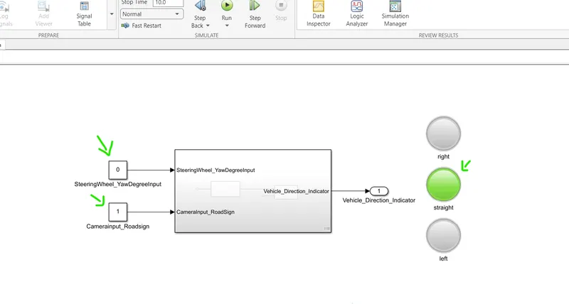
TEST CASE: 2 :
SteeringWheel_YawDegreeInput = 45
CameraInput_RoadSign = 1
DIRECTION OUTPUT= right
IMAGE FOR REFERENCE: 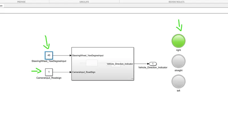
TEST CASE: 3 :
SteeringWheel_YawDegreeInput = -30
CameraInput_RoadSign = 1
DIRECTION OUTPUT= left
IMAGE FOR REFERENCE: 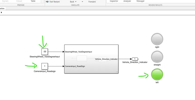
TEST CASE: 4 :
SteeringWheel_YawDegreeInput = -30
CameraInput_RoadSign = 0
DIRECTION OUTPUT= No output
IMAGE FOR REFERENCE: 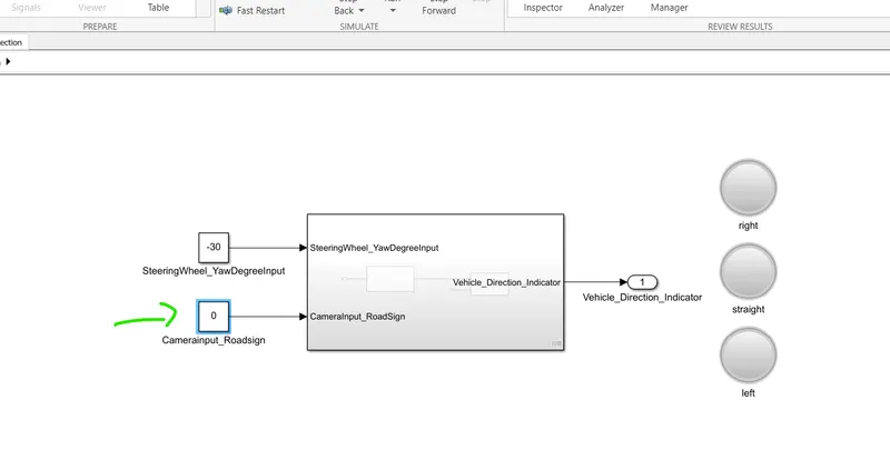
RESULTS:
In this project the given requirements are executed successfully.