Project 1 (Mini Project on Vehicle Direction Detection
Aim - To Create a Simulink Model as per the Requirement Data and Tag the Requirement Data to the Model.
Model -
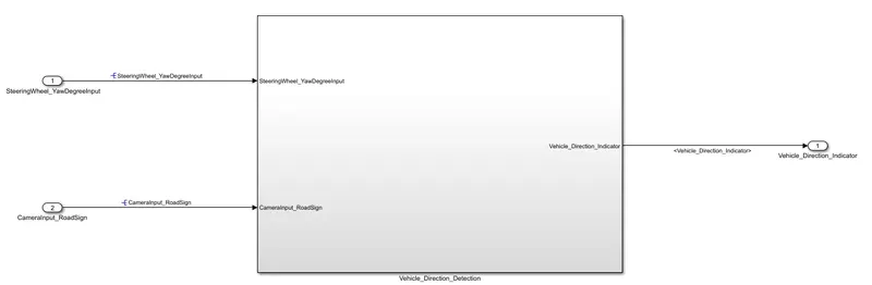
- We can see that SteeringWheel_YawDegreeInput and CameraInput_RoadSign are the two Inputs into the Vehicle_Direction_Detection Subsystem, which is our main Subsystem.
- Vehicle_Direction_Indicator will be output i.e it will tell us about the final direction indication to the driver.
Construction -
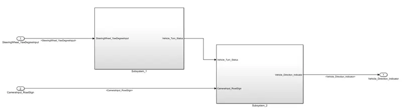
- This is inside the Vehicle_Direction_Detection Subsystem, Subsystem_1 will be about Requirement - 1 and Subsystem_2 will be about Requirement - 2.
- Let's look at the Subsystem_1 -
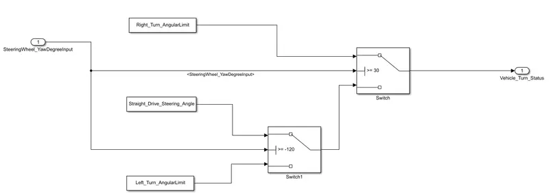
- We have SteeringWheel_YawDegreeInput as the Input with 3 constant blocks and 2 switch blocks in this Subsystem. The values of constant blocks are set by us from the Data list given to us. Let's look at the logic now -
- If the Input is equal or above 30 Right_Turn_AngularLimit will be passed on by 'Switch'. If the Input lies between -120 to 30, 'Switch1' and 'Switch' will pass Straight_Drive_Steering_Angle as the Output. If the Input is lesser than -120, Left_Turn_AngularLimit will be passed on.
- The output of this Subsystem will be Vehicle_Turn_Status.
- Let's look at Subsystem_2 -
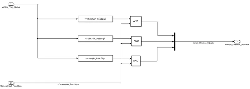
- In this Subsystem, we have two inputs Vehicle_Turn_Status and CameraInput_RoadSign. Then we have 3 Compare to Constant blocks, 3 Logical AND blocks and a MUX.
- The output of Subsystem_1 is one of the Inputs of SUbsystem_2. This Input will be compared with 3 constants, if the value match then '1' will be sent as an output from Compare block and if the value doesnt match '0' will be sent as an output from Compare block.
- Incase, if all the values come true the values are compared with the CameraInput_RoadSign. Logical AND Block helps us to determine the final direction, If CameraInput_RoadSign shows a true value for a direction only that direction will be sent to Vehicle_Direction_Indicator.
- MUX block combines all the signals and helps us to determine the final direction.
Data Dictionary -
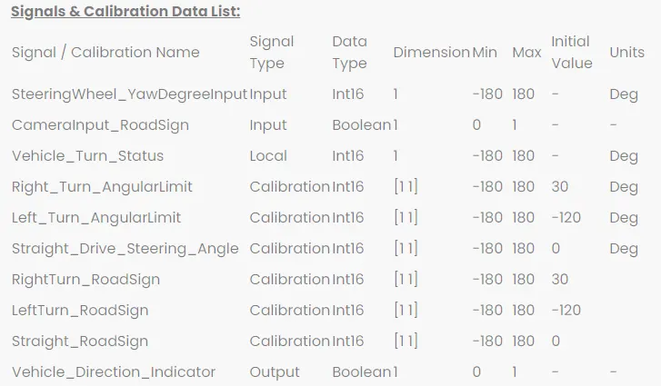
- This is the list of data given to us. We will create a data dictionary, create all the signals and load it with our model.
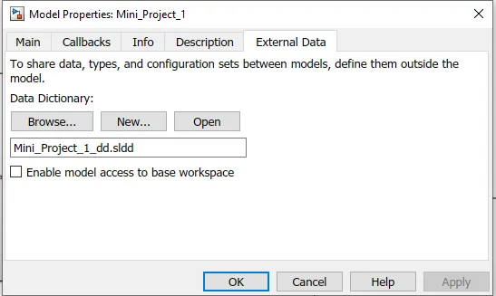
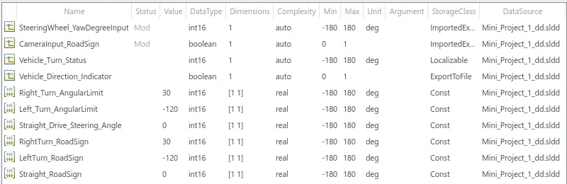
- We can create a SLDD from Model Properties. There will be a Section of External Data, we can load or create a new SLDD from there. As we can see below, Required Signals are created with appropriate value, data type, range, dimesnsion, unit and storage class.
Requirement Tagging -
- Requirement Tagging is also one of the Objective of the project. We can do the Requirement Tagging by simply selecting the heading of our requirement in the Word File and then Link the Selection in Word from Requirement section of subsystem.
- After clicking on the Requirement tagged, the Requirement document opens up and the Subsystem is highlighted.
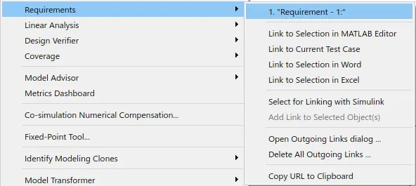

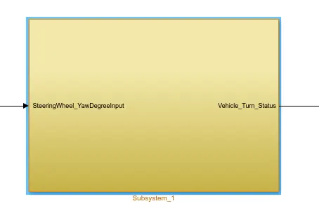
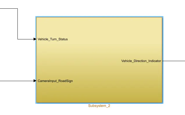
- Hence, Requirement Tagging is done Successfully.
Configuration Parameters -
- Few Configuration Settings are needed to be set in order to proceed for Code Generation, Results etc.
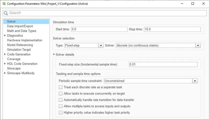
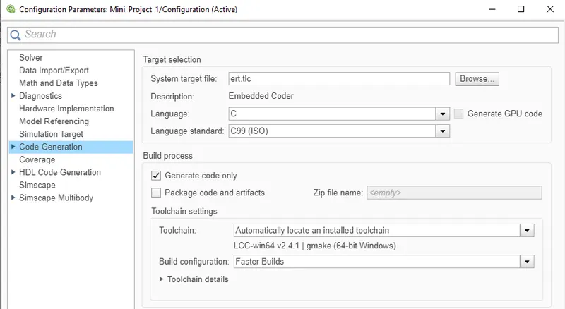
- We change the Solver Settings and Code Generation Settings in the Configuration Parameters. We dont touch Coverage Settings here as we are not interested in MIL or SIL for this Model. Further, during Model Advisor Checks we have to visit Configuration Parameters to eliminate the warnings shown in Model Advisor Checks.
Model Advisor -
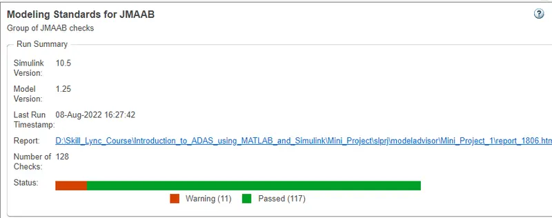
- Model Advisor tells us every small thing related to the Model, From maintaining MAAB guidelines to Resolving Signals of the model. We run few checks for this model as shown below -
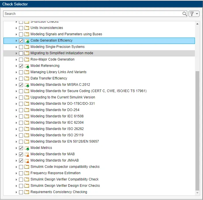
- The green ticks signal that every check is passed in that section. The Warning sign shows us that there are few warnings related to that section and we can try to eliminate them personally. Although,
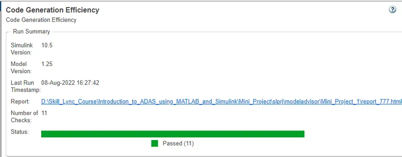
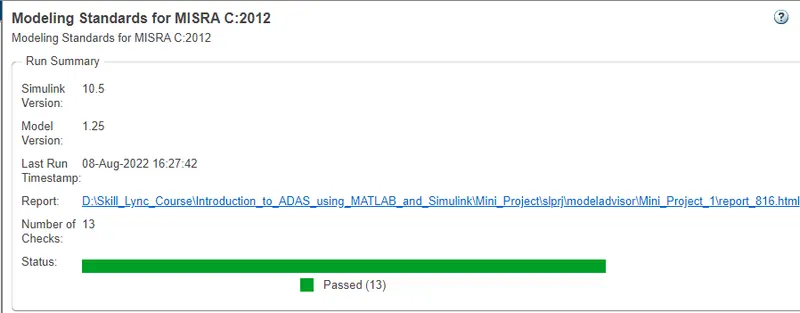
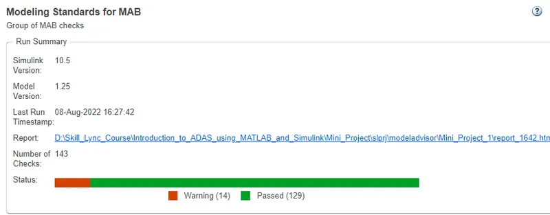
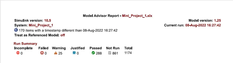
- After removing the warnings and running all the checks, we can download the report.
Code Generation -
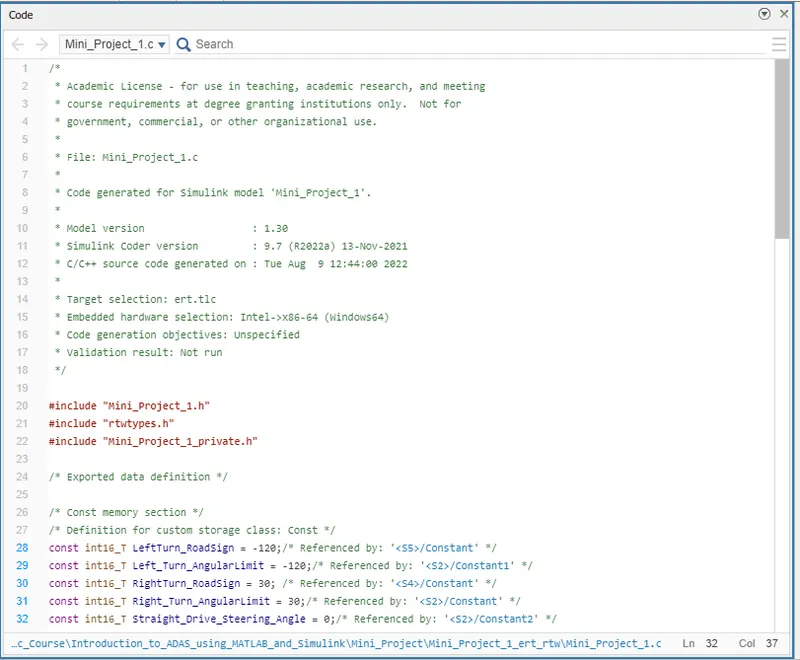
- Now we will proceed to the Code Generation process. We have already done the settings required in the Configuration Settings shown above. Now, we simply have to go to Apps section and click on Embedded Coder. Further, we click on Generate Code and we can a window pop-up with our Code. Simulink will create .c and .h files in our model folder, which means our code is successfully generated.
Results -
- We can set a value for SteeringWheel_YawDegreeInput from Model Explorer and observe the results by connecting a Display at Vehicle_Direction_Indicator. From Subsystem_2 we can clearly see the format of Turn Indicators. [1, 0, 0], [0, 1, 0] and [0, 0, 1] will show Right Direction, Left Direction and Straight Direction respectively.
- Case 1 -
SteeringWheel_YawDegreeInput > 30, CameraInput_RoadSign = 1, Direction = Right.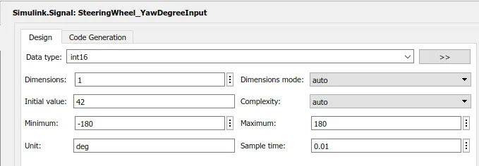
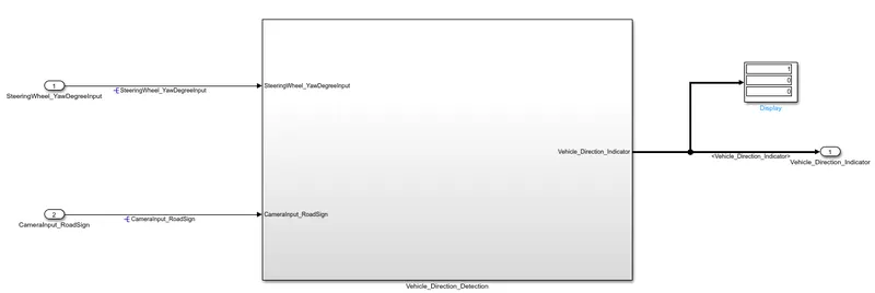
- As we can see, Display shows [1, 0, 0] which means the final direction is Right Turn.
- Case 2 -
SteeringWheel_YawDegreeInput < -120, CameraInput_RoadSign = 1, Direction = Left.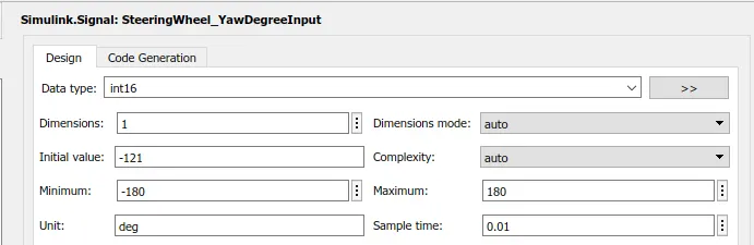
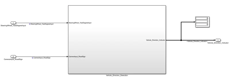
- As we can see, Display shows [0, 1, 0] which means the final direction is Left Turn.
- Case 3 -
SteeringWheel_YawDegreeInput between -120 to 30, CameraInput_RoadSign = 1, Direction = Straight.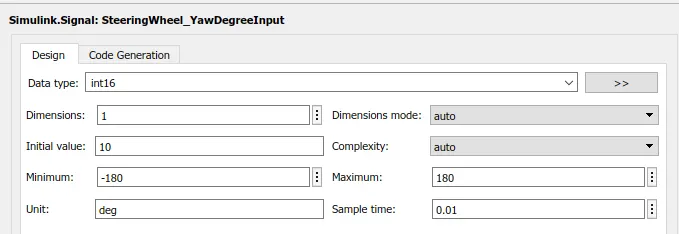
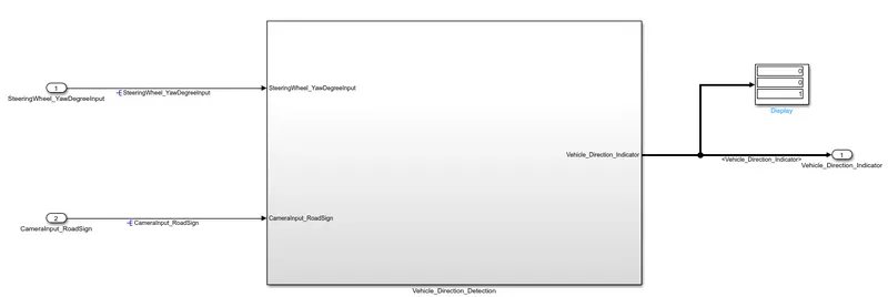
- As we can see, Display shows [0, 0, 1] which means the final direction is Straight.
- Hence, we have successfully created the model for the given requirements.