Week - 4
Washing Machine -
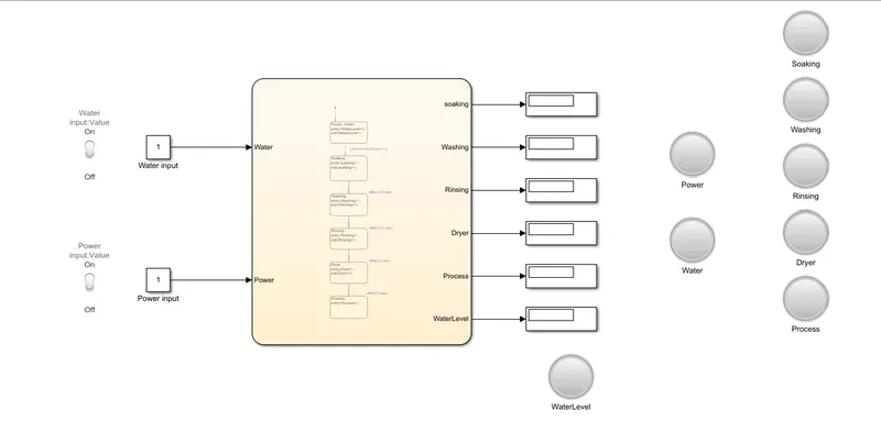
- This is the Basic Model Created to implement the control logic given to us.
- For the Input side of the model, we have 2 Constant Inputs, 2 Toggle Switches for the same.
- Then we have the Stateflow Chart - In which the control logic is implemented as per the problem given.
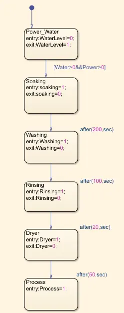
- From above, we can clearly see we have lots of state's in our model. The States are as follows - WaterLevel, Soaking, Washing, Rinsing, Dryer and Process. These all act as the output ports for our model.
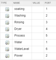
- So from the above image, it is clear that we have 2 Inputs - Water and Power and 6 Outputs - WaterLevel, Soaking, Washing, Rinsing, Dryer and Process. Hence, we have 8 Lamps for every port in the model for indication.
Procedure :-
Condition 1 - Power ON Indication and Water Supply Indication
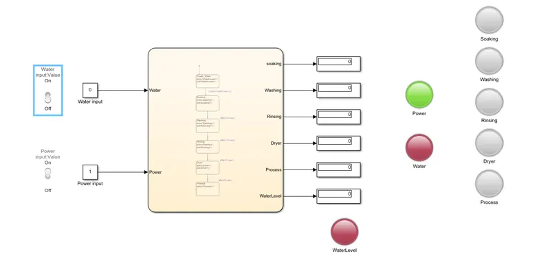
- As you can see from the above image, that Water Input has been kept OFF i.e 0. The Water Lamp and the WaterLevel Lamp will turn RED signalling there is no Water Supply available and the process is stopped. At the same time, we have the Power Switch ON i.e 1. The Power Lamp has indicated us that Power is available.
Condition 2 - Water Supply ON and then Soaking
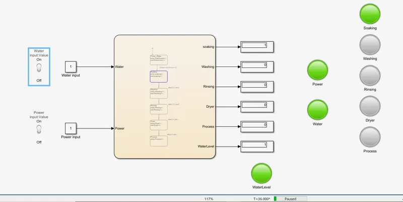
- As Power and Water both are available the Soaking process is run for total of 200 seconds as given in the control logic. Thus, Power Lamp, Water Lamp, WaterLevel Lamp and Soaking Lamp turns Green.
Condition 3 - Washing
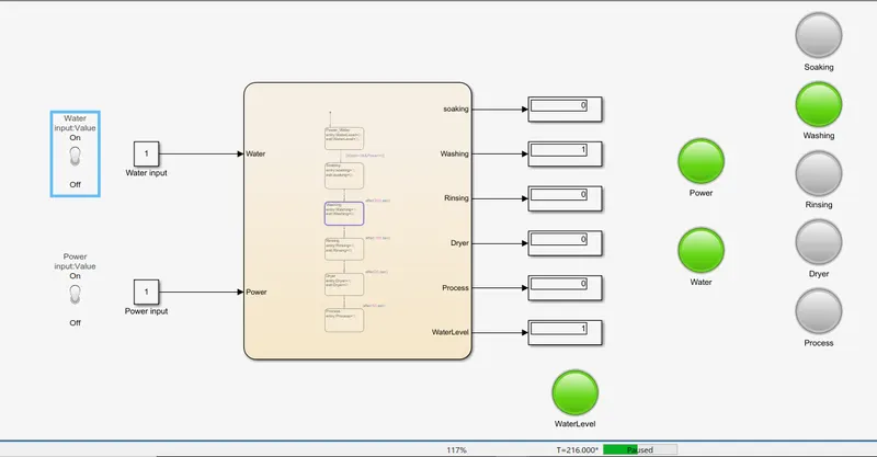
- As we can see from the time indicator that the Simulation time is more than 200 seconds, so the Washing Process is now activated. Hence, Washing Lamp has turned Green.
Condition 4 - Rinsing
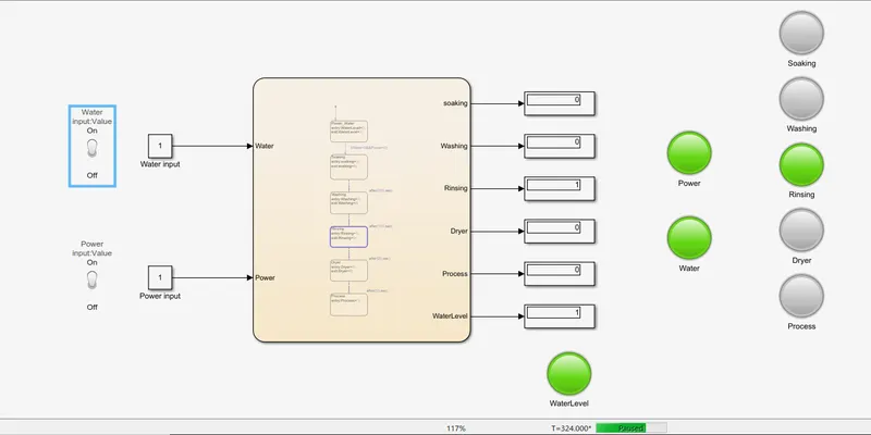
- After 100 seconds of Washing, Rinsing process is followed and the Rinsing Lamp has turned Green.
Condition 4 - Dryer
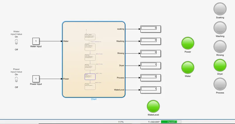
- Similarly, Dryer process is activated after the Rinsing Process is finished(20 Seconds) . Hence Dryer Lamp has turned Green.
Condition 5 - The End Process
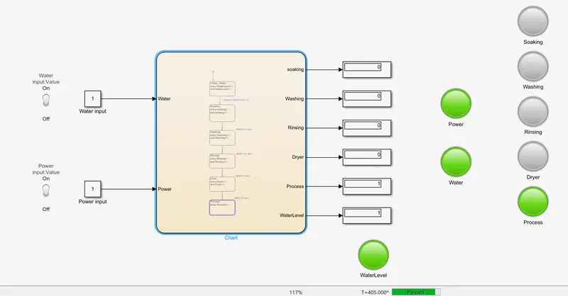
- After Dryer runs for 50 seconds, The Process Lamp is turned Green indicating the End of the Washing Machine Control Logic Processes. Hence, we have implemented the control logic of washing machine as per the given conditions.
Gear Shift -
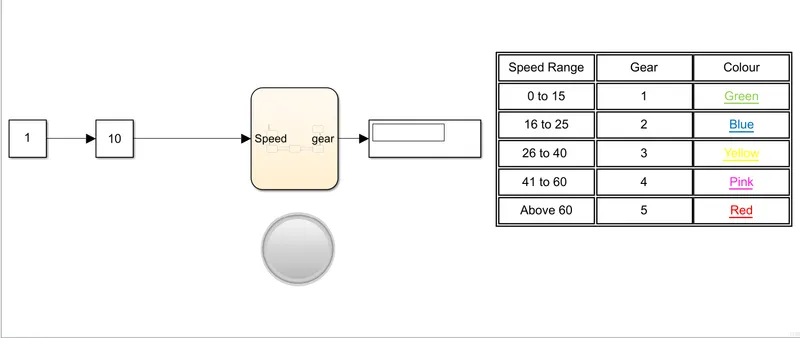
- This is the model we have created to implement the 'Gear Shift' mechanism.
- We have one input and one output only for this model. Speed is input given through Slider Gain, Gear will be our output.
- Slider Gain is used to vary the input while the simulation is running. Constant(1) is the input for Slider gain.
- Gear is connected with Display and Lamp to indicate which gear is runnung in the model.
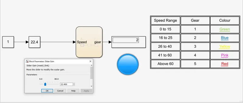
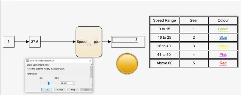
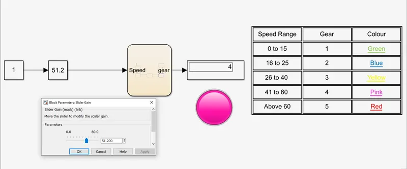
- On the right hand side, we have shown the table which contains Speed Range, Gear and Colour. The Lamp will turn Green, Blue, Yellow, Pink and Red for Gear 1, 2, 3, 4 and 5 Respectively.
- The Simulation Time for this model is set as Infinity as we need to change input when the Simulation is running.
- Let's have a look at the Stateflow Chart for this Model -
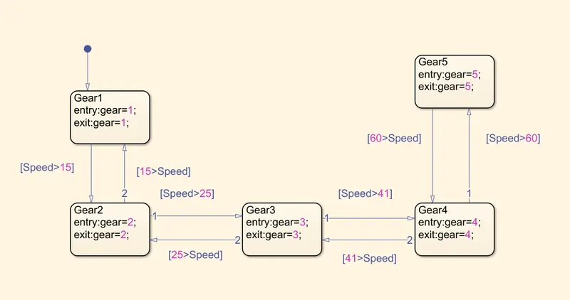
- The control Logic is implemented as per the given conditions. Further we have also added logic, when speed drops down the gear is changed as per the speed limits.
Procedure -
Condition 1 - Speed = 11.2, Gear = 1, Colour = Green.
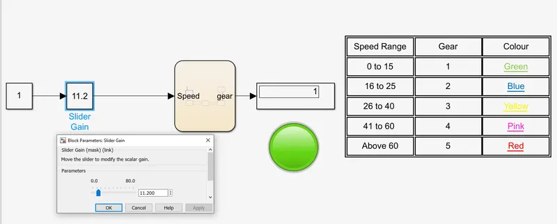
Condition 2 - Speed = 22.4, Gear = 2, Colour = Blue.
Condition 3 - Speed = 37.6, Gear = 3, Colour = Yellow.
Condition 4 - Speed = 51.2, Gear = 4, Colour = Pink.
Condition 5 - Speed = 73.6, Gear = 5, Colour = Red.
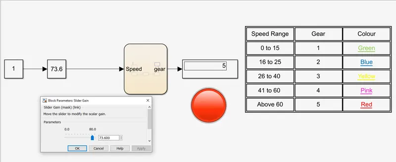
Hence, we have succesfully created Stateflow Chart and implemented the control logic for Gear Shift Mechanism.