Project 2 Adaptive Cruise Control
Aim - To Develop Adaptive Cruise Control feature as per the Requirement Document using MATLAB Simulink and follow all the MBD realted processes.
Model -
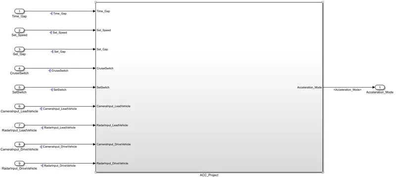
- This is our main subsystem named 'ACC_Project'. Inside this Subsystem we will find other subsystem required for the Adaptive Cruise Control feature.
- As we can see, there are total 9 Inputs and 1 output for this subsystem.
- Time_Gap, Set_Speed. Set_Gap, CruiseSwitch, SetSwitch, CameraInput_LeadVehicle, RadarInput_LeadVehicle, CameraInput_DriveVehicle, RadarInput_DriveVehicle are all the inputs. Acceleration_Mode becomes our sole output.
Construction -
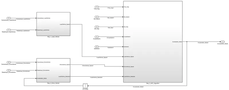
- This is Inside of ACC_Project SUbsystem. We can see 3 Subsystems here interconnected with each other those are the 3 Major Requirements for the Project. We will have a look at them below.
- Requirement 1 - Lead Vehicle:-
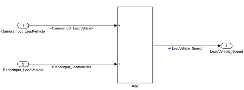
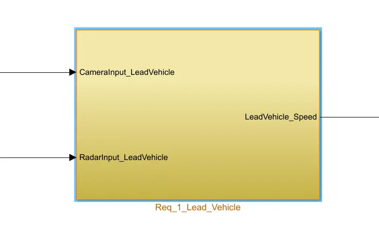
- This is our Requirement 1, there are two Inputs and one output for this Subsystem. CameraInput_LeadVehicle and RadarInput_LeadVehicle are the inputs. LeadVehicle_Speed is the output.
- Here, we simply add the two inputs which gives us the output.
- Requirement 2 - Drive Vehicle:-
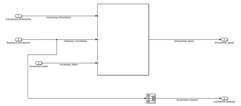
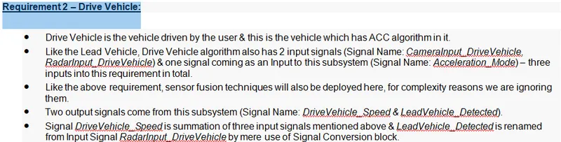
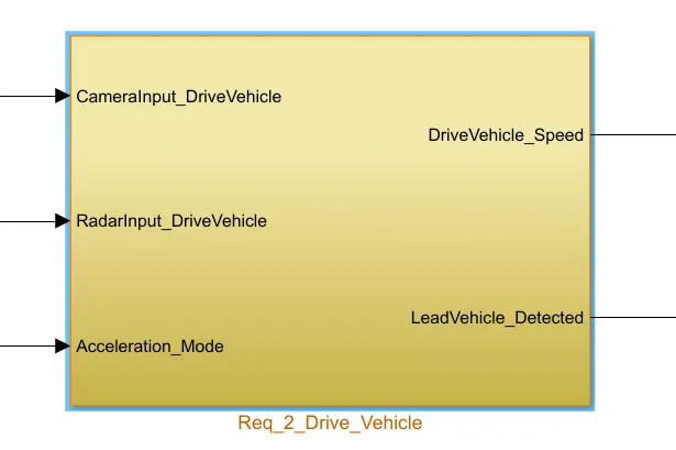
- This is our Requirement 2, here we can see 3 inputs and 2 outputs.
- CameraInput_DriveVehicle, RadarInput_DriveVehicle and Acceleration_Mode are the Inputs. DriveVehicle_Speed and LeadVehicle_Detected are our outputs.
- The 3 Inputs are directly added together which gives us DriveVehicle_Speed output. We have to not that, Acceleration_Mode is coming from Requirement 3 through a Unit Delay block.
- Further, RadarInput_DriveVehicle is Signal converted through Signal Converter Block which give us LeadVehicle_Detected our 2nd output for the Subsystem.
- Requirement 3 – Adaptive Cruise Control Algorithm:-
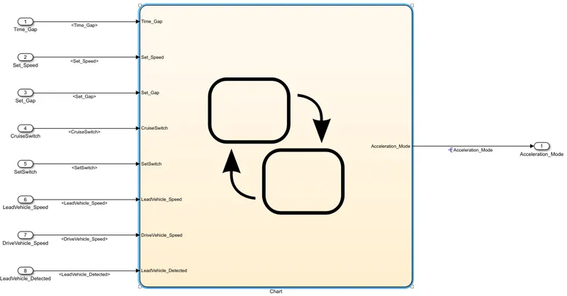
- This is our Requirement 3, In this Requirement we have to Implement State Machine Logic.
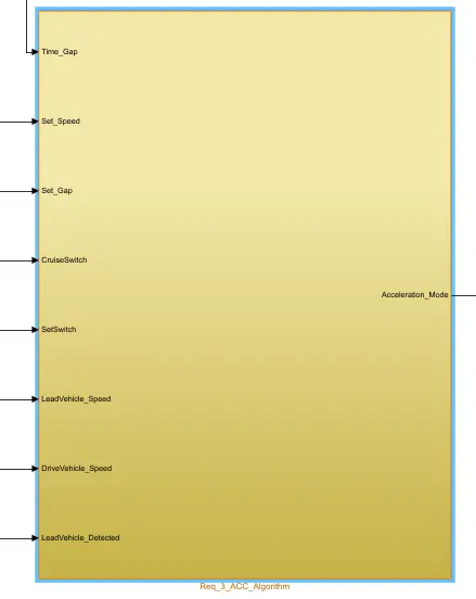
- Here, we have total of 8 Inputs and 1 Output. The sole output is Acceleration_Mode.
- Time_Gap, Set_Speed, Set_Gap, CruiseSwitch, SetSwitch are the direct inputs to the Stateflow chart. LeadVehicle_Speed, DriveVehicle_Speed and LeadVehicle_Detected are the inputs coming from Requirement 1 and Requirement 2 to this Stateflow Chart.
- Stateflow Chart:-
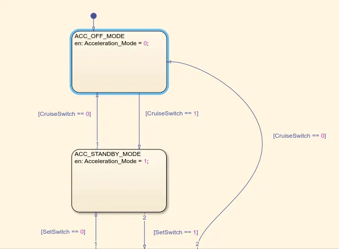
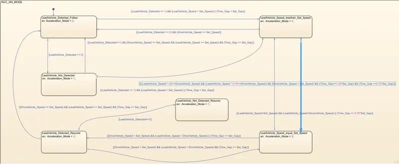
- There are 3 States in the Stateflow chart. ACC_ON_MODE, ACC_STANDBY_MODE and ACC_OFF_MODE.
- ACC_ON_MODE has 6 sub-states as shown above.
- The Conditions for switching the states and sub-states are given as per the instructions.
- This is the Symbols Pane for identifying all the Inputs and Outputs in the Stateflow chart.
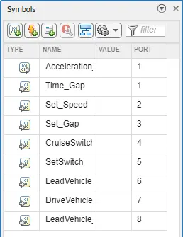
Configuration Parameters -
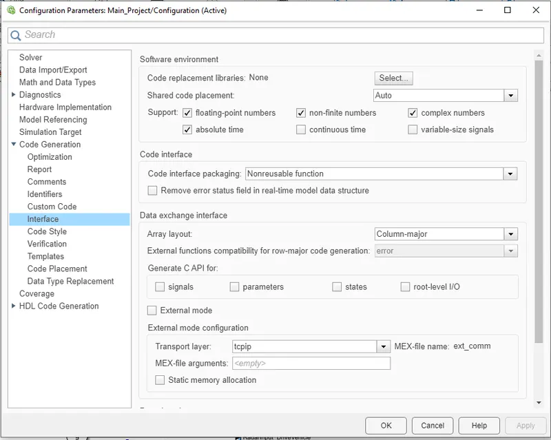
- Few Configuration Settings are needed to be set in order to proceed for Code Generation and Results. We have to enable 'Support Floating Numbers' under Code Generation settings as instructed.
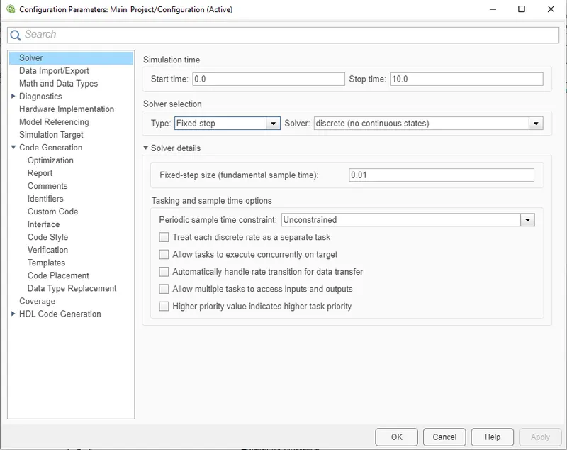
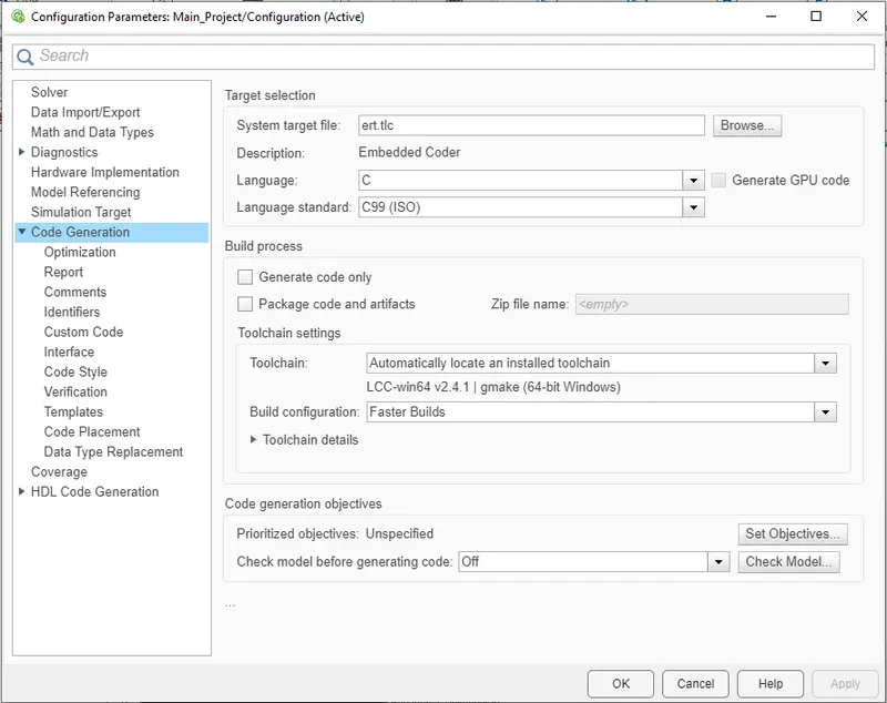
- We change the Solver Settings and Code Generation Settings in the Configuration Parameters. As we can see Fixed-Step and Discrete Solver for this project, even Fixed-Step Size is also set.
- In Code Genereation Settings, we select the Embedded Coder i.e ert.tlc in system target file.
- Further, we have also enabled 'Support Floating Numbers'.
- For any other changes, we have to visit COnfiguration Parameters during Model Advisor Checks.
Data Dictionary -
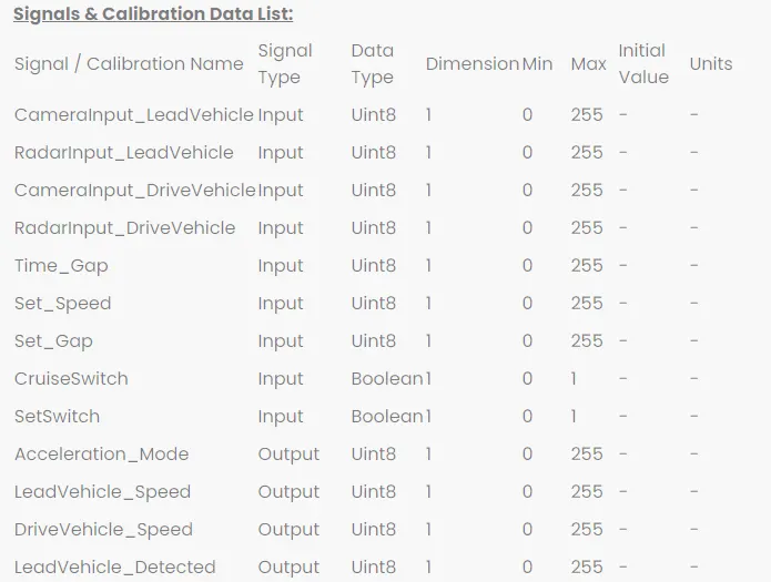
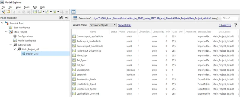
- This is the list of data given to us. We will create a data dictionary, create all the signals and load the dictionary to our model.
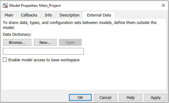
- We can create a SLDD from Model Properties. There will be a Section of External Data, we can load or create a new SLDD from there.
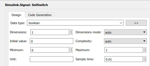
- As we can see below, Required Signals are created with appropriate value, data type, range, dimesnsion, unit, sample time and storage class.
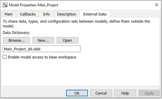
- To check which SLDD is loaded, we can simply go to Model Properties and check External Data.
Requirement Tagging -
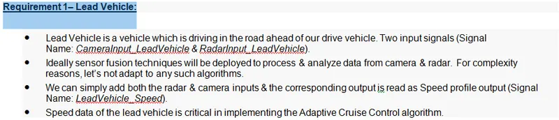
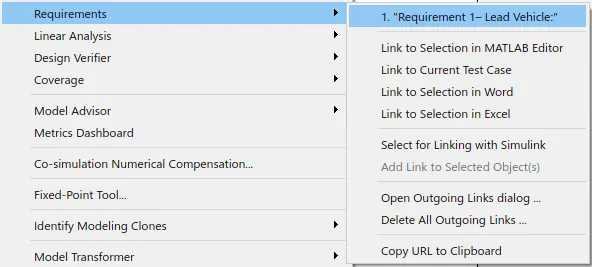
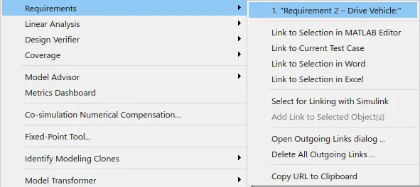
- Requirement Tagging helps us to identify the Requirement related to the Subsystem. In this Project we have 3 major Requirements. We can simply select the Subsystem and Link to Selection in the in Word, Excel, Test Case etc. When we click on the Linked Requirement, the file pops up with the Selection Highlighted.
- Requirement 1 -
- Requirement 2 -
- Requirement 3 -
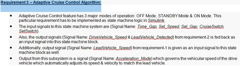
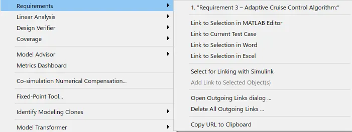
- Thus, Requiremenrt Tagging is done for all the Requirements.
Model Advisor Report -
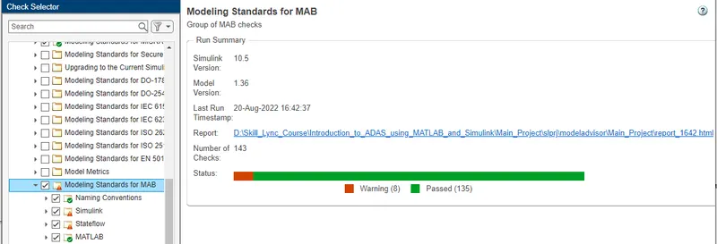
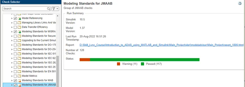
- Model Advisor checks everything related to the Model. Modelling standards for MAB, JMAAB, MISCRA are checked here. We run few selected checks for this model as shown below -
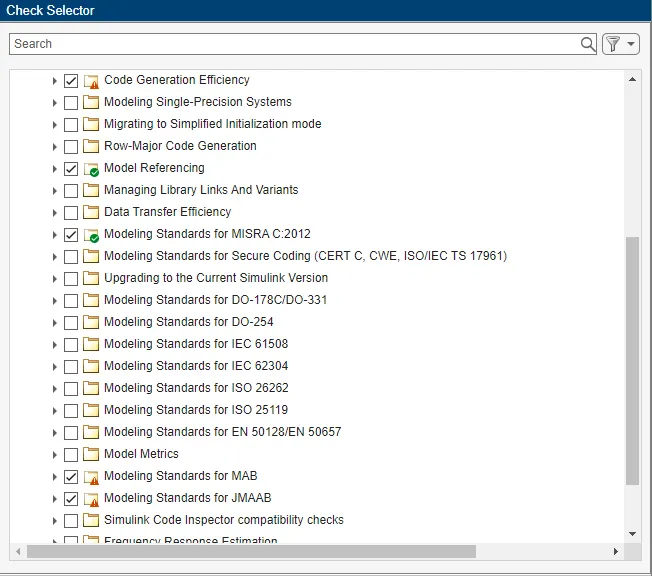
- As we can see Green ticks signals that every check is passed while warning symbol signals that there are warnings related to these checks and we can go and personally eliminate those warnings. Not all the warnings can be eliminated, we have to keep the warnings as low as possible. Let's look at every check we ran -
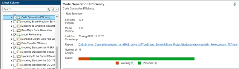
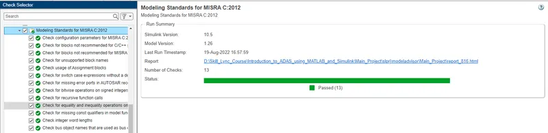
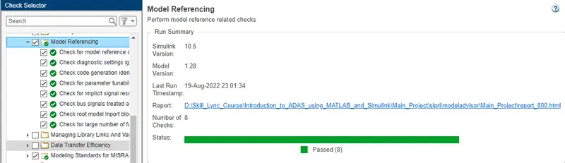
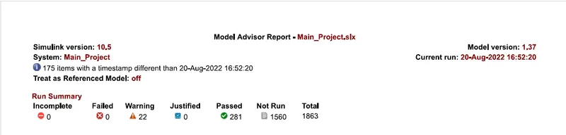
- After minimising the warnings and eliminiating the failures, we can generate the Model Advisor Report in html or pdf format.
Code Generation -
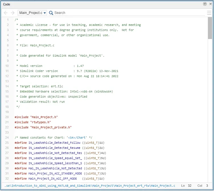
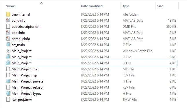
- After Generating the Model Advisor Report, we will proceed to the Code Generation process. We have already done the settings required in the Configuration Settings shown above. Now, we simply have to go to Apps section and click on Embedded Coder. Further, we click on Generate Code and we can a window pop-up with our Code. Simulink will create .c and .h files in our model folder, which means our code is successfully generated.
Results -
- Now, we will look at the Results for this Project. We can change the values of our inputs from Model Explorer. For Analysing the results we have connected a display at the output side and we have chnaged the Simulation time to 'inf' as we have to check the results in Stateflow as well. Infinity Simulation time will show us the exact Stateflow state for the output.
- We will have a look at ACC_OFF_MODE, ACC_STANDBY_MODE and few sub-states of ACC_ON_MODE. We are not looking at all the sub-states of ACC_ON_MODE because it is a lenghty process and something which is not the main aim of this project.
- Case 1 -
CruiseSwitch = 0, Mode = ACC_OFF_MODE, Acceleration_Mode = 0.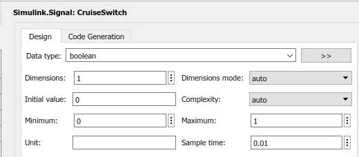
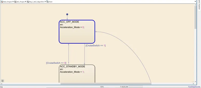
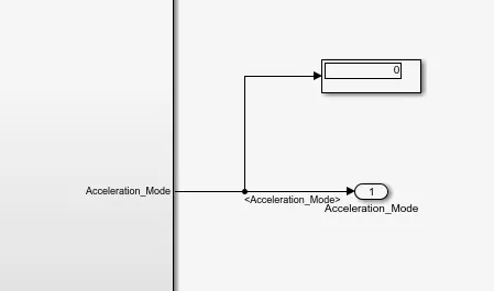
- As CruiseSwitch = 0, ACC_OFF_MODE will be active and we will obtain Acceleration_Mode output as 0.
- Case 2 -
CruiseSwitch = 1, SetSwitch = 0 Mode = ACC_STANDBY_MODE, Acceleration_Mode = 1.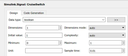
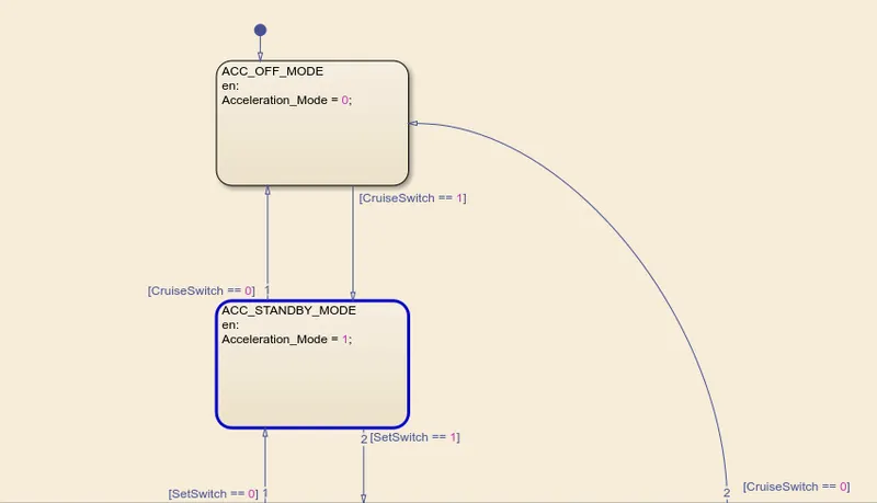
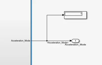
- As we can see, CruiseSwitch is set to 1 but SetSwitch is 0. This condition will activate ACC_STANDBY_MODE as ACC_ON_MODE cannot be active if SetSwitch is 0. Thus, we obtain output as 1.
- Case 3 -
CruiseSwitch = 1, SetSwitch = 1 Mode = ACC_ON_MODE, Sub-State = LeadVehicle_Detected_Follow, Acceleration_Mode = 2, All the LeadVehicle and DriveVehicle Inputs = 1, TimeGap = 5, SetSpeed = 1, SetGap = 4.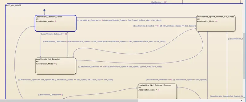
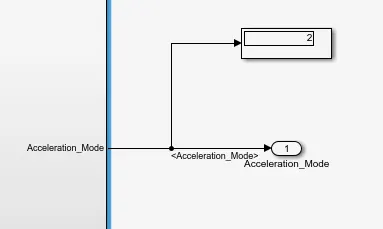
- All the Inputs have been set accordingly to obtain LeadVehicle_Detected_Follow Sub-state. This Sub-state gives us Acceleration_Mode output as 2. We can see the output in the display block.
- The Simulation sticks with this sub-state because the inputs does not satisfy any condition which takes the Simulation to any other sub-state.
- As LeadVehicle_Detected is not equal to 0, Simulation will not enter LeadVehicle_Not_Detected. Similarly, the Simulation will not enter LeadVehicle_Speed_lessthan_Set_Speed as SetSpeed is less than LeadVehicle_Speed and TimeGap is greater than SetGap.
- Case 4 -
CruiseSwitch = 1, SetSwitch = 1 Mode = ACC_ON_MODE, Sub-State = LeadVehicle_Speed_lessthan_Set_Speed, Acceleration_Mode = 4, All the LeadVehicle and DriveVehicle Inputs = 1, TimeGap = 5, SetSpeed = 5, SetGap = 6.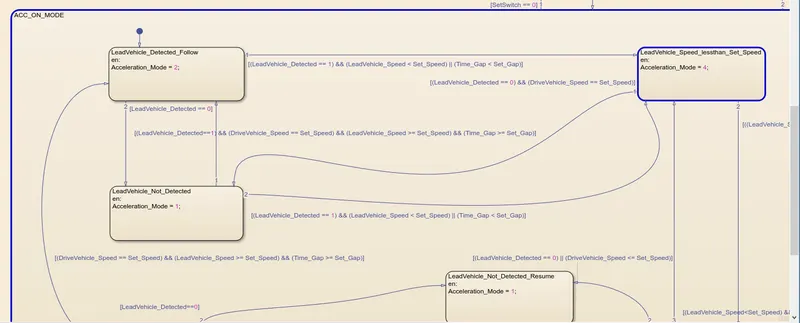
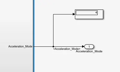
- All the Inputs have been set accordingly to obtain LeadVehicle_Speed_lessthan_Set_Speed Sub-state. This Sub-state gives us Acceleration_Mode output as 4. We can see the output in the display block.
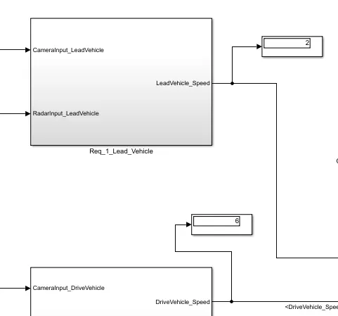
- The Simulation will not enter LeadVehicle_Not_Detected as As LeadVehicle_Detected is equal to 1. Simillarly, the Simulation will not enter LeadVehicle_Speed_equal_Set_Speed because our inputs do not satisfy LeadVehicle_Speed*1.25>=DriveVehicle_Speed. We can check this condition below.
- Case 5 -
CruiseSwitch = 1, SetSwitch = 1 Mode = ACC_ON_MODE, Sub-State = LeadVehicle_Not_Detected, Acceleration_Mode = 1, RadarInput_DriveVehicle = 0, TimeGap = 5, SetSpeed = 5, SetGap = 6.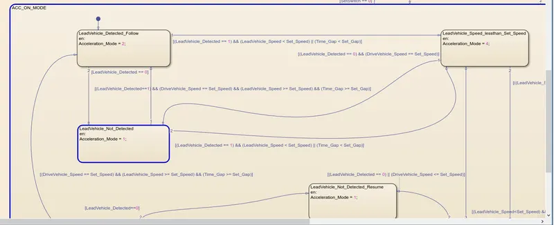

- All the Inputs have been set accordingly to obtain LeadVehicle_Not_Detected Sub-state. This Sub-state gives us Acceleration_Mode output as 1. We can see the output in the display block.
- The Simulation enters this sub-state because LeadVehicle_Detected = 0, we obtain this value because our input RadarInput_DriveVehicle = 0. We know that LeadVehicle_Detected is obtained from Input Signal RadarInput_DriveVehicle by mere use of Signal Conversion block.
- We can see the LeadVehicle_Detected value below -
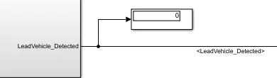
- Unless LeadVehicle_Detected value changes to 1, the simulation will not enter any other sub-state.
- So, we have shown all the Stateflow States and few Sub-states for the Adaptive Cruise Control Project.
- Hence, we have successfully created the model for Adaptive Cruise Control feature as per the Requirement and implemented all the MBD related processes.