Vehicle Direction Detection
AIM: To design a model which detects the vehicle direction using steering wheel input which is compared against traffic signs detected using camera (installed in vehicle in itself) to know whether vehicle is turning/moving in permitted direction or not.
OVERVIEW:
Identifying the direction of the vehicle is one of the important & diverse features in Autonomous driving & Advanced Driver Assistance Features. This particular sub-feature of identifying the direction of vehicle is basically identifying the direction the vehicle is taking based on the camera input.
Camera reads the road signs & stores into its memory with unique values for left turn, right turn & straight drive. Depending on the direction it is taking, final indication is given to the driver – as an indication if he is driving in the recommended direction or not.
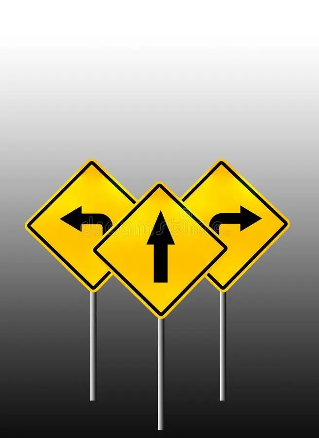
MODEL REQUIREMENTS:
Requirement - 1:
- Steering wheel input as yaw rate (Signal name: SteeringWheel_YawDegreeInput) is the input for this system.
- This is compared against 3 angular values, one each for left turn, right turn & straight drive (Calibration Values: Right_Turn_AngularLimit, Left_Turn_AngularLimit, Straight_Drive_Steering_Angle) to say which specific direction the steering wheel is turning towards.
- Use switch blocks to compare & develop this requirement. Keep this requirement in a subsystem & output of this requirement is a local signal (Signal Name: Vehicle_Turn_Status).
Requirement – 2:
- Keep this requirement as a separate subsystem. Inputs to this requirement are local signal from requirement 1 (Signal Name: Vehicle_Turn_Status) & an input signal from camera (Signal Name: CameraInput_RoadSign), which confirms the occurrence of a road sign.
- Signal Vehicle_Turn_Status is compared against calibration values (Calibration Values: RightTurn_RoadSign, LeftTurn_RoadSign, Straight_RoadSign), if each of them is found equal, then each of the three corresponding output is compared against the camera input signal,
- Using a logical operator block, only one among them is finally given as output signal (Signal Name: Vehicle_Direction_Indicator).
Signals & Calibration Data List:
|
Signal / Calibration Name |
Signal Type |
Data Type |
Dimension |
Min |
Max |
Initial Value |
Units |
|
SteeringWheel_YawDegreeInput |
Input |
Int16 |
1 |
-180 |
180 |
- |
Deg |
|
CameraInput_RoadSign |
Input |
Boolean |
1 |
0 |
1 |
- |
- |
|
Vehicle_Turn_Status |
Local |
Int16 |
1 |
-180 |
180 |
- |
Deg |
|
Right_Turn_AngularLimit |
Calibration |
Int16 |
[1 1] |
-180 |
180 |
30 |
Deg |
|
Left_Turn_AngularLimit |
Calibration |
Int16 |
[1 1] |
-180 |
180 |
-120 |
Deg |
|
Straight_Drive_Steering_Angle |
Calibration |
Int16 |
[1 1] |
-180 |
180 |
0 |
Deg |
|
RightTurn_RoadSign |
Calibration |
Int16 |
[1 1] |
-180 |
180 |
30 |
|
|
LeftTurn_RoadSign |
Calibration |
Int16 |
[1 1] |
-180 |
180 |
-120 |
|
|
Straight_RoadSign |
Calibration |
Int16 |
[1 1] |
-180 |
180 |
0 |
|
|
Vehicle_Direction_Indicator |
Output |
Boolean |
3 |
0 |
1 |
- |
- |
MODELLING OF VEHICLE DIRECTION DETECTION SYSTEM IN SIMULINK:
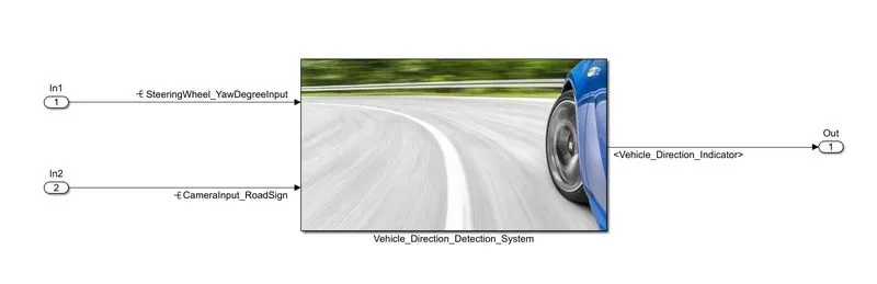
(i) The following figure shows the top view for the required model:
(ii) Let us observe the model in detail by diving into the subsystem:
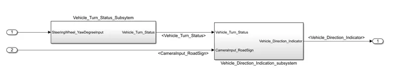
(iii) Now, let us look into the 'Vehicle Turn Status' subsystem:
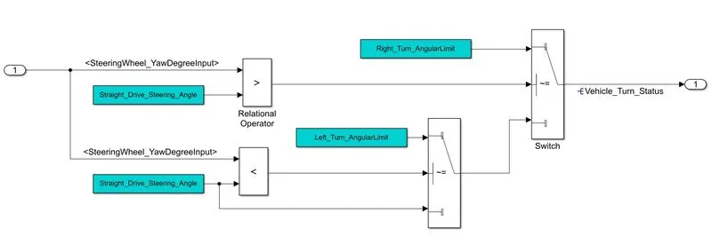
- This subsystem is modelled according to the data provided in Requirement 1.
- Here, initially the input signal, SteeringWheel_YawDegreeInput is compared to the Straight_Drive_Steering_Angle (whose value is zero degrees) using 'greater than' and 'less than' relational operator and there outputs are applied to the control input or second input of the switch.
- Right_Turn_Angular_Limit (30°) and Left_Turn_Angular_Limit (-120°) are applied at first input terminals of swtiches.
- Straight_Drive_Steering_Angle (0°) is applied at the third input terminal of 2nd switch whose output is applied at the third input of first switch.
- The output signal of the first switch is also the output of this subsystem is named as Vehicle_Turn_Status.
- The switches passes through the first input terminals if the the input 2 satisfies the selected criteria otherwise it passes through the third input terminal of the switch.
- The criteria of the switch is choosen as u2~=0 (i.e, second input is not equal to the zero).
(iv) Now, let us look inside the 'Vehicle Direction Indication' subsytem:
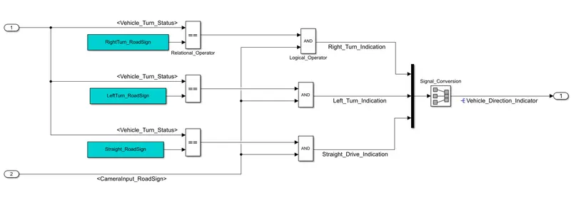
- This subsystem is modelled according to the Requirement 2.
- Initially, input signal, Vehicle_Turn_Status is compared to Right_Turn_RoadSign (30°), Left_Turn_RoadSign (-120°) & Straight_RoadSign (0°) using 'equal to' relational operator blocks.
- The outputs of the relational operators are applied to the first input terminals of three logical operators i.e, AND blocks and another input signal CameraInput_RoadSign is applied to the second input terminals of AND blocks.
- The output signals of logical operators are applied at the inputs of Bus creator whose output is named as Vehicle_Direction_Indicator which is also output signal of this subsystem and required model.
TAGGING THE REQUIREMENTS TO THE SIMULINK MODEL:
Here, we need to tag the two subsystems named as Vehicle_Turn_Status_Subsystem and Vehicle_Direction_Indication_Subsystem to Requirement 1 and Requirement 2 respectively which are present in the Requirement document.
Make sure the Requirement document is stored in the current directory of the MATLAB.
Open the document and select the text (which is to be tagged) in the Requirement document as shown below.

Right click on the subsystem which is needed to be tagged, which opens list of options as shown below.
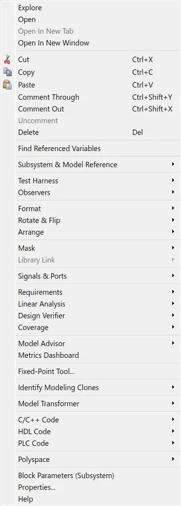
Click on Requirements from list of options, which displays few options as shown below:
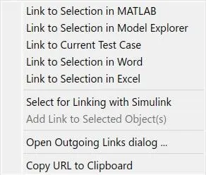
By clicking on the Link to Selection in Word, the tagged subsystem flashes around two times which means the tagging is carried successfully.
Likewise, Requirement 2 is also tagged to its corresponding subsystem.
All the tagging links are stored in .slmx extension file in the current directory.
STEPS TO CREATE SIMULINK DATA DICTIONARY (SLDD):
Click on Model settings in Modelling tab of simulink tool bar and then click on Model properties which will open window as shown below:
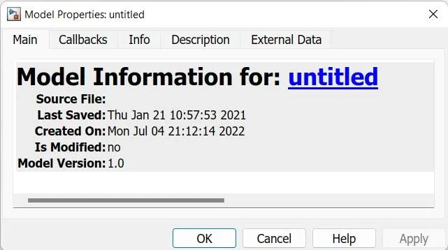
From above window, click on External Data option then interface is displayed as shown below:
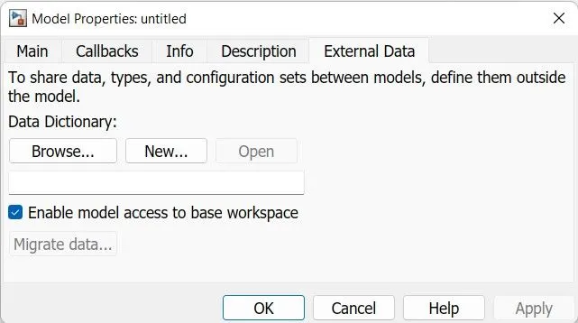
Now, click on New option which will create a file with an extension .sldd for that you can name it as per your requirement.
Here, we had untick the 'Enable model access to base workspace' which forces the created .sldd file not to accessing the base workspace.
After creating .sldd file, we can open it from your directory where it was saved or by clicking on Model data icon on bottom left corner of simulink as shown below:
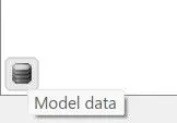
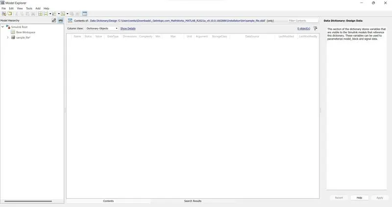
By clicking on above icon, it will ask to select one of the two options i.e, Model workspace and External data. Click on External data then a window will be opened within the Model Explorer as shown below:
Creating new signals and constants (calibrations) in SLDD file:
By double clicking on Model file name (here, it was 'sample_file') in above window, Design Data option will be displayed then click on it.
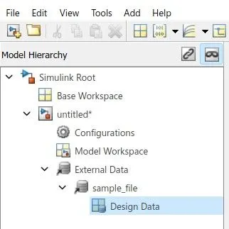
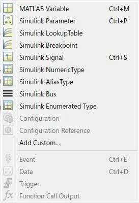
Now by clicking on Add option in tool bar, a list of options will be displayed (as shown below) from which you can add required new simulink signals & parameters (constants).
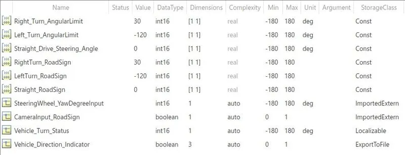
When we click on simulink signal and parameter (constant/calibration), then those will be added to file as shown below:

Now, you can edit/select the Initial value, Data type, Dimensions, Complexity Min, Max, Unit, Storage class as per given information in input file for signals and parameters.
Whenever you edit/add the data into the SLDD, right click on the file name in Model Hierarchy and then click on 'Save Changes'.
Setting the sample time for signals in SLDD:
Select the signal for which you want to change the sample time, which opens a window as shown below:
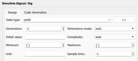
For all signals, Sample time is changed to 0.01 seconds (given) from default value of -1 and then click on Apply at the bottom right of the screen.
The following image shows all the required objects (signals and parameters) are added to the SLDD file:
RESOLVING SIGNALS & ITS PROPAGATION:
We have created objects (signals and parameters)data dictionary for the signals and calibration values.
When created Parameters used in simulink, those are directly linked to the data dictionary but that doesn't happens for signals.
So, we need to resolve the signals to corresponding simulink signal objects inorder to do that follow below steps:
(i) Right click on the signal which need to be resolved, which displays list of options as shown below.
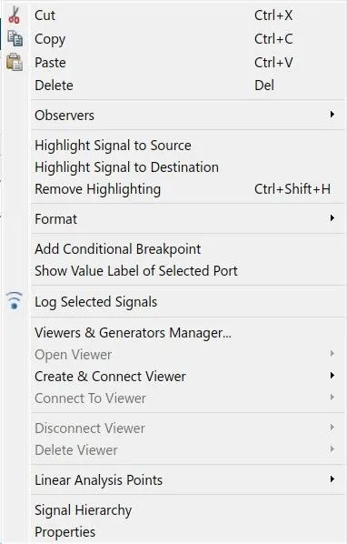
(ii) Now, click on Properties, then a window is displayed as shown below:
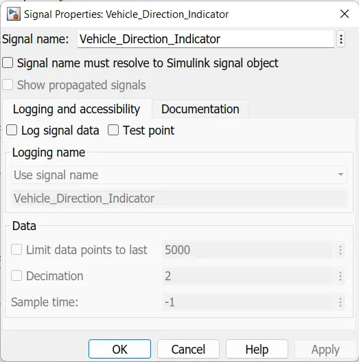
(iii) Finally, tick the box beside the 'Signal name must resolve to Simulink signal object' and click on OK.
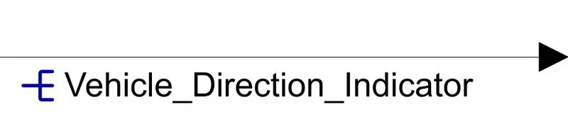
(iv) After resolving the signal to its object, a resolution icon appears onto the left of label on the signal.
Propagation of signals:
To write signal names at every instant of signal occurance is hectic. So we can label the signal once, and we can propagate the label names at every occurance of signal.
For propagation of signals, follow same steps as for resolving the signal until signal properties window appears as shown below:
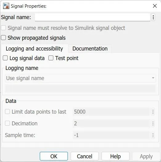
Now, enable the option 'Show propagated signals' and click on OK. After propagation of signal, the label is displayed inside the angle brackets (<>).
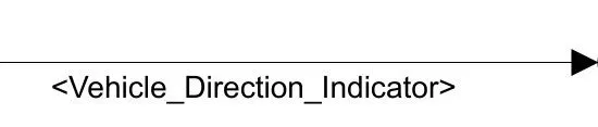
Shortcut: You can even double click on the signal & type the label name as <> and then hitting the Enter button, does the propagation of signals.
MODEL ADVISORY REPORT:
Click on Modelling tab in tool bar of simulink.
Now, click on Model Advisor option which opens a window as shown below:
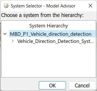
You can select whole model or particular subsystem and click on OK. (Here, whole model is selected). Then, a window a shown below is displayed:
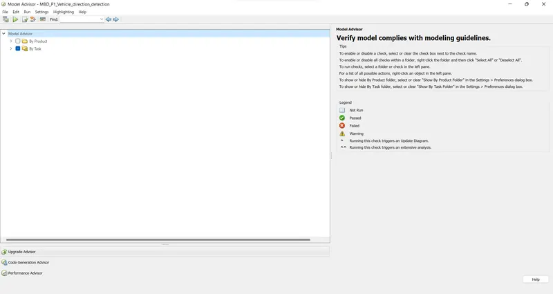
Now, you can select different types of checks to be run by checking the tick box beside them. Here, only Modelling Standards for MAAB from By task category is selected as shown below. Click on Run Selected Checks for report.
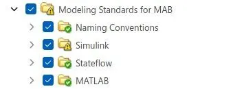
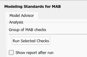
The following figure shows summarized report for the model:

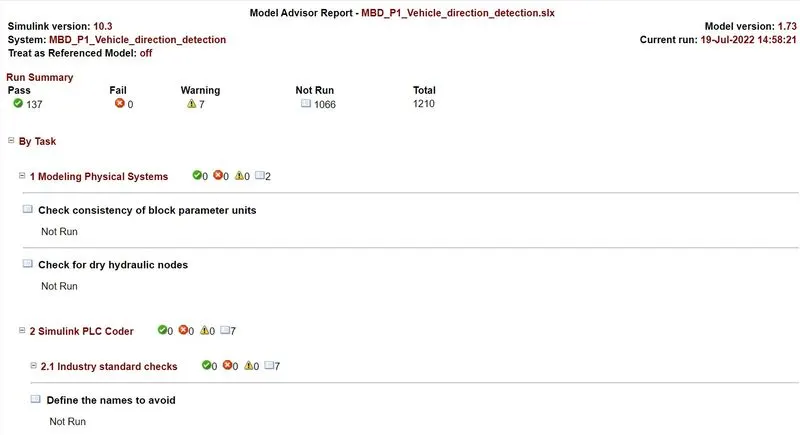
We can even run individual checks (which initially displayed as errors/warnings) as many times we need, until we rectify them.
Model Advisory Report (in detail) is generated when you click on Generate Report in above window. The following image is a part of Model Advisory Report.
CODE GENERATION:
- Head to 'Configuration parameters' by clicking on Model settings in Modelling tab from tool bar of simulink.
- Change the solver type to Fixed-step and solver to Discrete (non continous states) as shown in below figure.

- Now, click on Code generation in Configuration parameters, by clicking on 'Browse' option, change the 'System target file' to ert.tlc (Embedded codder).

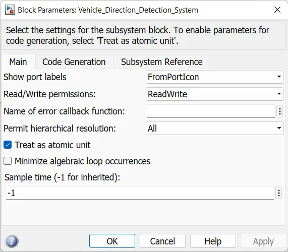
- Now, right click on main subsystem and click on 'Block parameters (Subsystem)' and tick the box for Treat as atomic unit and click on OK.
Again, right click on the main subsystem, select C/C++ code >> Generate S function from the list of options displayed. Then a window is displayed as shown below:
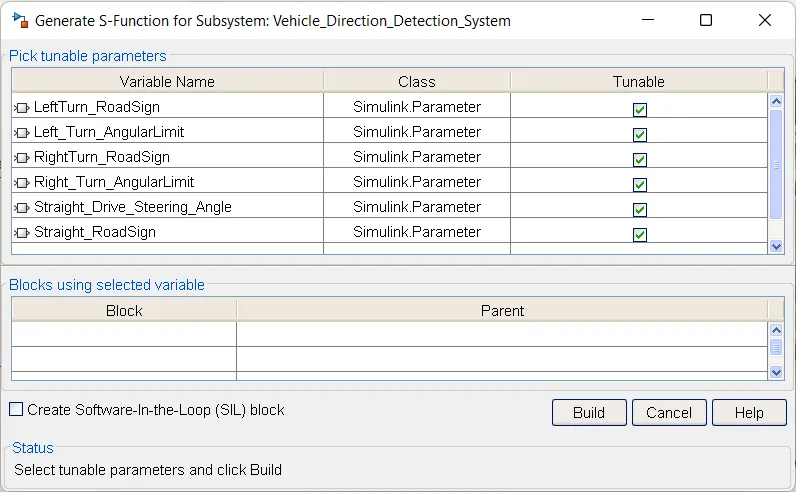
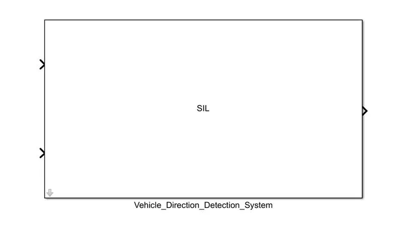
Now, check the box for Create Software-In-the-Loop (SIL) block and click on Build. Then a model is created as shown below:
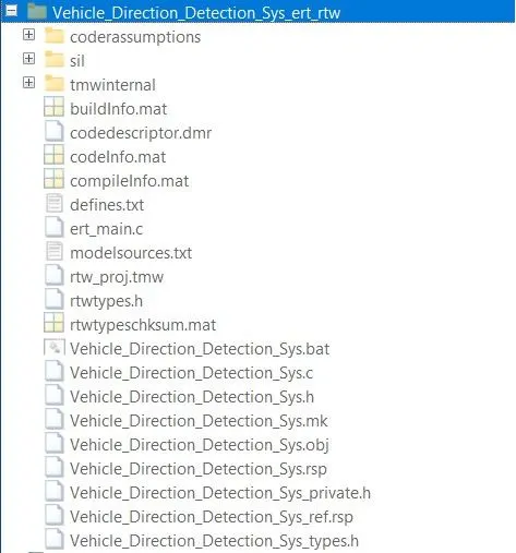
Also, a file named with Subsystem_name_ert_rtw is created in current directory which includes files with .c & .h extensions as shown below:
We can access the C-code from above files or Click on Harness icon(as shown below) in bottom right of the simulink model page.
Now, select the Enter Code Perspective, then interface appears as shown below:
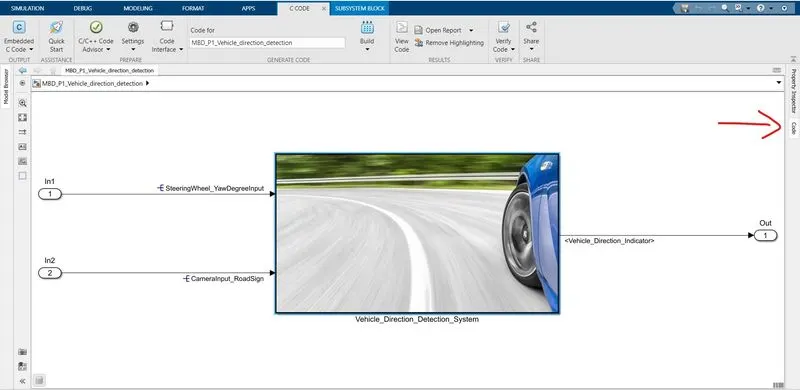
By clicking on Code in tool strip onto your right side of screen (shown in above image through indication), the generated code is displayed as shown below:
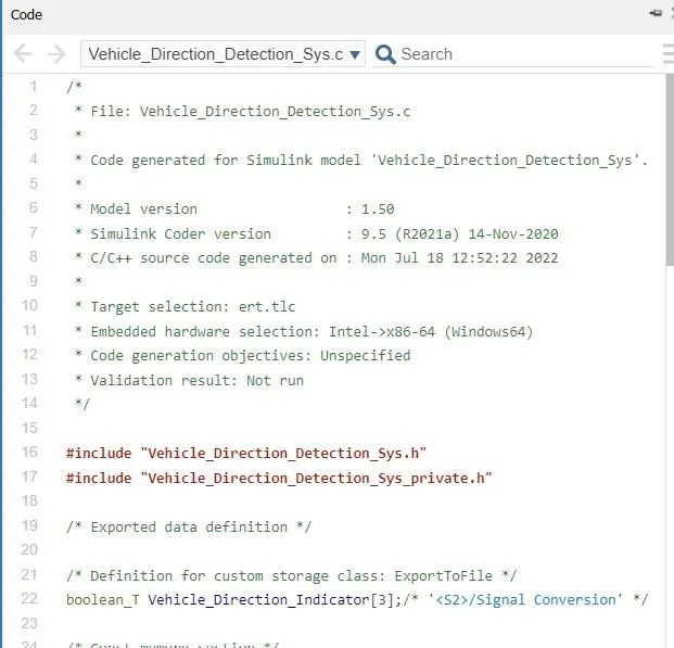
The following code shows the complete generated C-code for designed model:
/*
 * File: Vehicle_Direction_Detection_Sys.c
 *
 * Code generated for Simulink model 'Vehicle_Direction_Detection_Sys'.
 *
 * Model version                  : 1.50
 * Simulink Coder version         : 9.5 (R2021a) 14-Nov-2020
 * C/C++ source code generated on : Mon Jul 18 12:52:22 2022
 *
 * Target selection: ert.tlc
 * Embedded hardware selection: Intel->x86-64 (Windows64)
 * Code generation objectives: Unspecified
 * Validation result: Not run
 */

#include "Vehicle_Direction_Detection_Sys.h"
#include "Vehicle_Direction_Detection_Sys_private.h"

/* Exported data definition */

/* Definition for custom storage class: ExportToFile */
boolean_T Vehicle_Direction_Indicator[3];/* '/Signal Conversion' */

/* Const memory section */
/* Definition for custom storage class: Const */
const int16_T LeftTurn_RoadSign = -120;/* Referenced by: '/Constant1' */
const int16_T Left_Turn_AngularLimit = -120;/* Referenced by: '/Constant1' */
const int16_T RightTurn_RoadSign = 30; /* Referenced by: '/Constant' */
const int16_T Right_Turn_AngularLimit = 30;/* Referenced by: '/Constant' */
const int16_T Straight_Drive_Steering_Angle = 0;/* Referenced by:
                                                 * '/Constant3'
                                                 * '/Constant4'
                                                 */
const int16_T Straight_RoadSign = 0;   /* Referenced by: '/Constant2' */

/* Real-time model */
static RT_MODEL_Vehicle_Direction_De_T Vehicle_Direction_Detection__M_;
RT_MODEL_Vehicle_Direction_De_T *const Vehicle_Direction_Detection__M =
  &Vehicle_Direction_Detection__M_;

/* Model step function */
void Vehicle_Direction_Detection_Sys_step(void)
{
  /* local block i/o variables */
  int16_T Vehicle_Turn_Status;

  /* Outputs for Atomic SubSystem: '/Vehicle_Direction_Detection_System' */
  /* Switch: '/Switch' incorporates:
   *  Constant: '/Constant3'
   *  Constant: '/Constant4'
   *  Inport: '/SteeringWheel_YawDegreeInput'
   *  RelationalOperator: '/Relational Operator'
   *  RelationalOperator: '/Relational Operator1'
   *  Switch: '/Switch3'
   */
  if (SteeringWheel_YawDegreeInput > Straight_Drive_Steering_Angle) {
    /* Switch: '/Switch' incorporates:
     *  Constant: '/Constant'
     */
    Vehicle_Turn_Status = Right_Turn_AngularLimit;
  } else if (SteeringWheel_YawDegreeInput < Straight_Drive_Steering_Angle) {
    /* Switch: '/Switch3' incorporates:
     *  Constant: '/Constant1'
     *  Switch: '/Switch'
     */
    Vehicle_Turn_Status = Left_Turn_AngularLimit;
  } else {
    /* Switch: '/Switch' incorporates:
     *  Constant: '/Constant3'
     *  Switch: '/Switch3'
     */
    Vehicle_Turn_Status = Straight_Drive_Steering_Angle;
  }

  /* End of Switch: '/Switch' */

  /* SignalConversion: '/Signal Conversion' incorporates:
   *  Constant: '/Constant'
   *  Constant: '/Constant1'
   *  Constant: '/Constant2'
   *  Inport: '/CameraInput_RoadSign'
   *  Logic: '/Logical Operator'
   *  Logic: '/Logical Operator1'
   *  Logic: '/Logical Operator2'
   *  RelationalOperator: '/Relational Operator'
   *  RelationalOperator: '/Relational Operator1'
   *  RelationalOperator: '/Relational Operator2'
   */
  Vehicle_Direction_Indicator[0] = ((Vehicle_Turn_Status == RightTurn_RoadSign) &&
    CameraInput_RoadSign);
  Vehicle_Direction_Indicator[1] = ((Vehicle_Turn_Status == LeftTurn_RoadSign) &&
    CameraInput_RoadSign);
  Vehicle_Direction_Indicator[2] = ((Vehicle_Turn_Status == Straight_RoadSign) &&
    CameraInput_RoadSign);

  /* End of Outputs for SubSystem: '/Vehicle_Direction_Detection_System' */
}

/* Model initialize function */
void Vehicle_Direction_Detection_Sys_initialize(void)
{
  /* (no initialization code required) */
}

/* Model terminate function */
void Vehicle_Direction_Detection_Sys_terminate(void)
{
  /* (no terminate code required) */
}

/*
 * File trailer for generated code.
 *
 * [EOF]
 */
RESULT:
Let us test our model by applying few test cases:
(i) Here, SteeringWheel_YawDegreeInput = 15° and CameraInput_RoadSign =1 are applied as inputs.
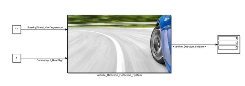
From 'Vehicle_Direction_Indication_Subystem', we can say that the first output displayed is for Right turn indication, second for Left turn indication and last for Straight drive indication.
We can observe that the applied steering angle is equal to 15° (steering wheel rotated in clockwise direction) which is between 0° to 30°, so output 1 is displayed for 'Right turn indication' only which means vehicle is turning in permitted direction only.
(ii) Here, SteeringWheel_YawDegreeInput = 15° and CameraInput_RoadSign =0 are applied as inputs.
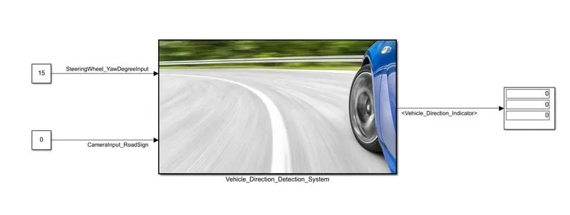
Even though the applied steering angle is between 0 to 30°, output 1 is not displayed for 'Right turn indication' because the CamperInput_RoadSign is zero (camera didn't detected the traffic sign). So, driver must be aware whether he is driving in permitted direction or not.
(iii) Here, SteeringWheel_YawDegreeInput = -40° and CameraInput_RoadSign =1 are applied as inputs.
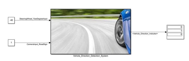
The applied steering angle is equal to -40° (steering wheel is rotated in anti-clockwise direction) which is between -120° to 0°, so output 1 is displayed for 'Left turn indication' only which means vehicle is turning in permitted direction only.
(iv) Here, SteeringWheel_YawDegreeInput = 0° and CameraInput_RoadSign =1 are applied as inputs.
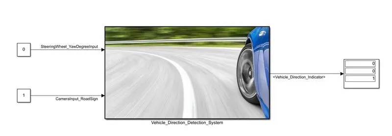
The applied steering angle is equal to 0° (steering wheel is not rotated), so output 1 is displayed for 'Straight drive indication' only which means vehicle is moving in permitted direction only.
The following table shows all possible inputs and their corresponding outputs of the model:
| Steering Angle | Camera_Input |
Right turn Indication |
Left Turn Indication |
Straight Drive Indication |
| 0 to 30° | 1 | 1 | 0 | 0 |
| 0 to 30° | 0 | 0 | 0 | 0 |
| -120° to 0° | 1 | 0 | 1 | 0 |
| -120° to 0° | 0 | 0 | 0 | 0 |
| 0° | 1 | 0 | 0 | 1 |
| 0° | 0 | 0 | 0 | 0 |
SUMMARY:
- Model is designed according to the given requirements.
- SLDD file is created and linked to the model.
- All given signals in the model are resolved to simulink.signal objects in SLDD.
- Model Advisory Report is generated for the model.
- C-code is generated for the designed model.
- Model is verified by applying few test cases.
Links which opens the source pages for some of the above uploaded images: