Project 1 (Mini Project on Vehicle Direction Detection
I am online student from EV batch -16
Aim:-
To create an MBD model in MATLAB Simulink model for Vehicle Direction Detection as per the specified requirements.
Objective:-
Develop Matlab Simulink model as per necessity.
select sample time 0.01 sec for all signals.
Do requirement tagging to requirement 1 and requirement 2.
MBD changes, Change in data dictionary and code generation is added in this project.
storage signals are classified according to the requirement like input, output, constant and localizable.
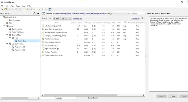
- First of all, create a sldd file according to the data given. And include every little notation and specify thee signals.
- Create a new folder and include every file in it otherwise the model will not run properly.
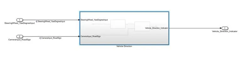
- Now according to requirements make subsystem of vehicle direction with two inputs and one output.
- In subsystem, it requires two subsystems as it mentioned requirement1 and requirement2.
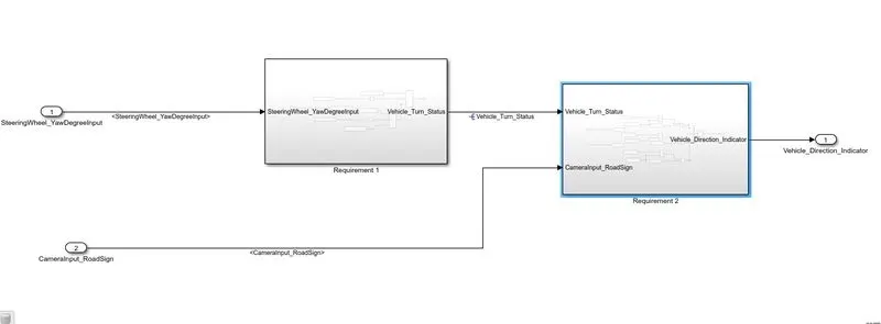
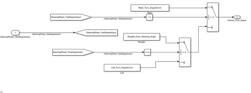
- Requirement 1 needed Steering wheel input as yaw rate (Signal name: SteeringWheel_YawDegreeInput) is the input for this system.
- Compared against 3 angular values, one each for left turn, right turn & straight drive (Calibration Values: Right_Turn_AngularLimit, Left_Turn_AngularLimit, Straight_Drive_Steering_Angle) to say which specific direction the steering wheel is turning towards.
- Use switch blocks to compare & develop this requirement. Keep this requirement in a subsystem & the output of this requirement is a local signal (Signal Name: Vehicle_Turn_Status).
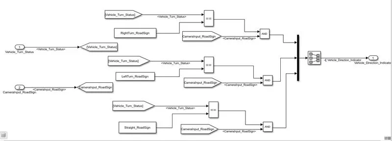
- For requirement a Keep this requirement as a separate subsystem. Inputs to this requirement are a local signal from requirement 1 (Signal Name: Vehicle_Turn_Status) & an input signal from the camera (Signal Name: CameraInput_RoadSign), which confirms the occurrence of a road sign.
- Signal Vehicle_Turn_Status is compared against calibration values (Calibration Values: RightTurn_RoadSign, LeftTurn_RoadSign, Straight_RoadSign), if each of them is found equal, then each of the three corresponding output is compared against the camera input signal.
- Using a logical operator block, only one among them is finally given as output signal (Signal Name: Vehicle_Direction_Indicator).
The next step is to solve signals and propagate them.
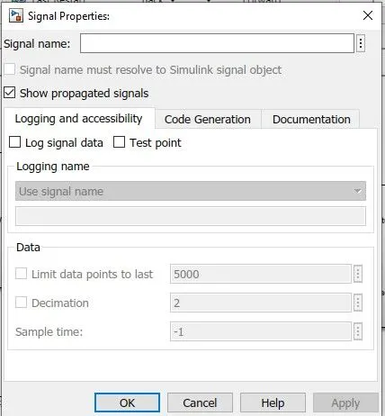
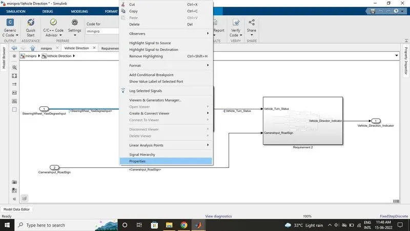
- As given below image select one signal > properties and give a signal name with a checkbox with signal name must resolve.
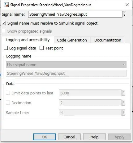
- To propagate a select signal go to Properties and check show propagated signals another option is to select signal double click and then write <> signal will be propagated.
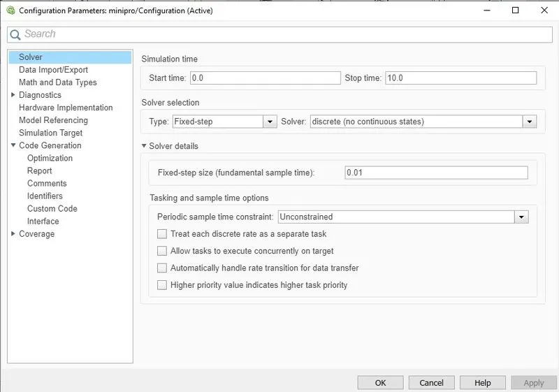
- Change the solver configuration settings from variable time step to fixed-step with discrete solver and stepsize would be 0.01seconds.
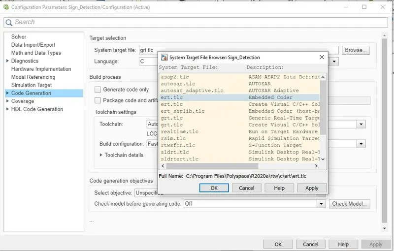
- Choose the target file ert.tlc embedded codder.
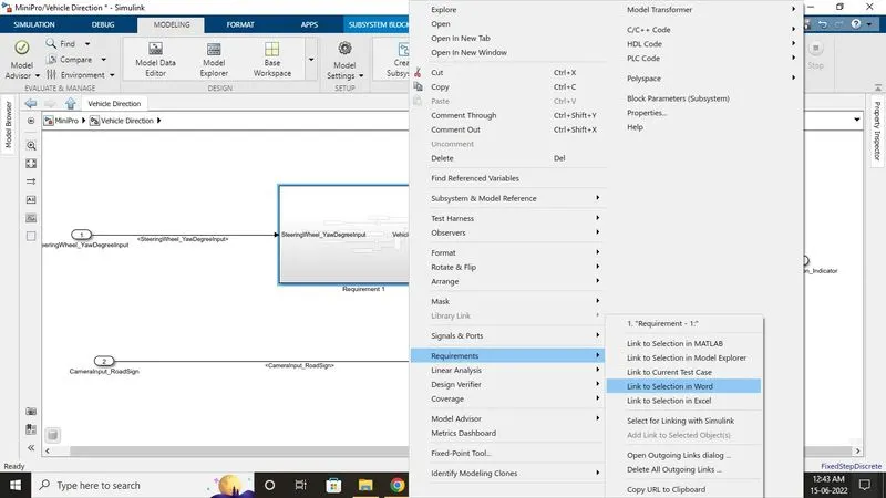
- To tag the system select requiremtn1 subsystem right-clicks> requirements and select link to word it will link to the word file and information will be open of that subsystem.
- Same process with requirement 2.
- To Check errors and warnings model advisor check is a must to comply with different guidelines.
- Open model advisor check and just select modelling standards with MAB.
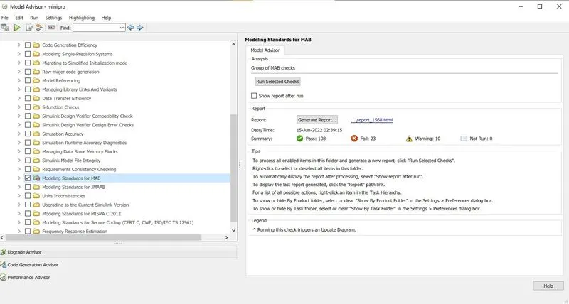
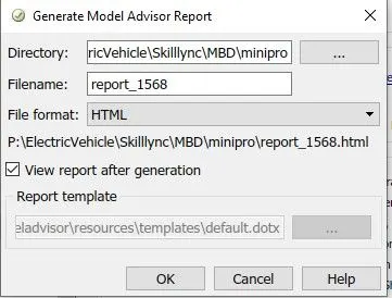
- It will generate a report with warnings fails and pass. Minimum warnings and failures should be there. It will create a report in HTML and saves it in a folder.
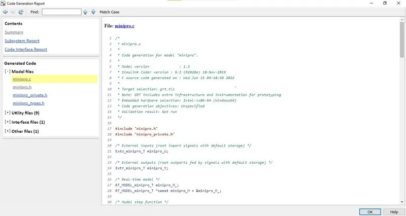
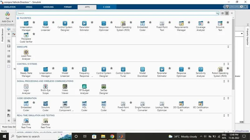
- To generate code go to APPS >Simulink coder.
- To generate code system target file should be in grt.tlc format then only it generates C code.
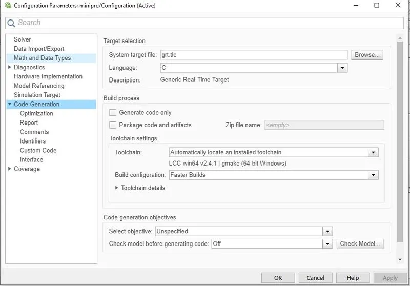
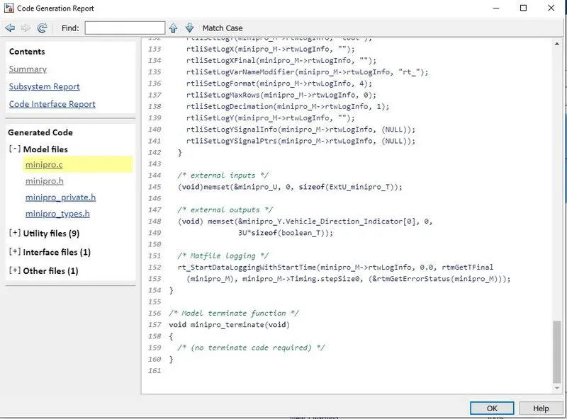
- Now select the build option to generate the whole system code.

- Code file will generate with the .c extension and we can see it in the base workspace too.