Project 1 (Mini Project on Vehicle Direction Detection
Objective -
- To develop a MBD compliant Simulink model for the Vehicle Direction Determination following the instructions as per Requirement Document.
- To create a Data Dictionary File for the model.
- To Tag the requirements in Requirement Document.
- To generate C code for the developed model.
- To perform Model in Loop (MIL) Test.
- To perform Software in Loop (SIL) Test
Development of the Model -
1. Creation of Data Dictionary File -
- In the Modelling Tab, select Link Data Dictionary Option.
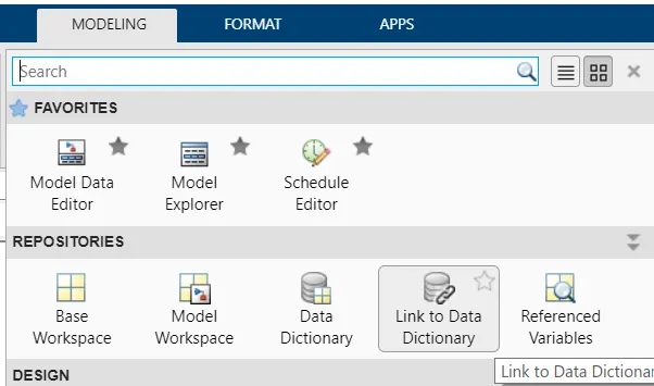
Fig 1 - Link to Data Dictionary Option in Modelling Tab
- Add a New File and rename the file.
- Also, uncheck the "Enable model access to base workspace".
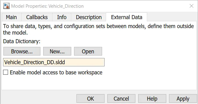
Fig 2 - Link to Data Dictionary Dialogue Box
- Click OK.
- From the Modelling tab, open Model Explorer.
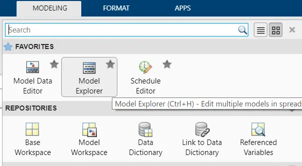
Fig 3 - Model Explorer in Modelling Tab
- In the Model Explorer window, locate the sldd file in the External Data.
- Make entries to sldd file from the Requirement Document.
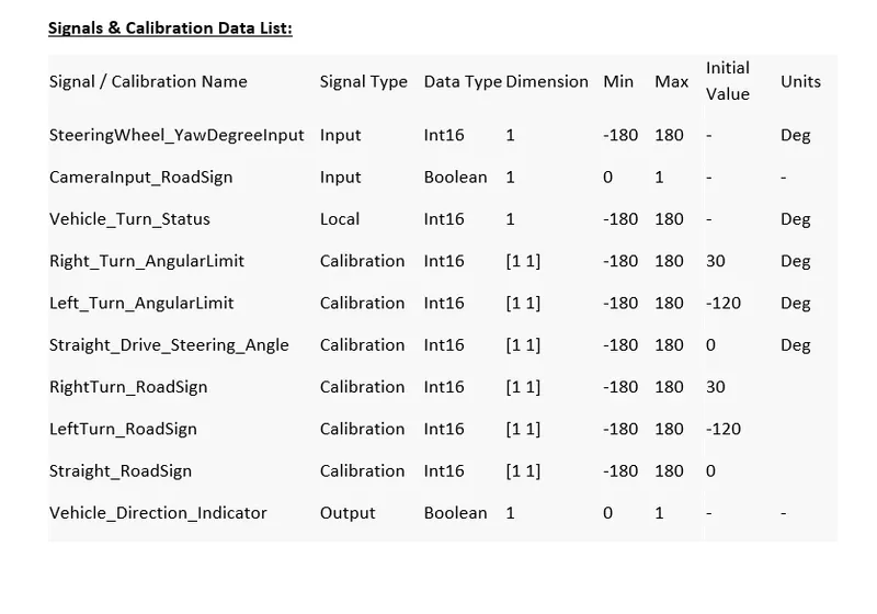
Fig 4 - Signals and Parameters List from Required Document
- For the Input Signal,Storage Class used is ImportedExtern.
- For the Output Signal, Storage Class used is Export to File.
- For the Local Signal, Storage Class used is Localizable.
- For the Clibration Signal, Storage Class used is Const.
- After making all the entries in the sldd file, Save the file.
- The sldd file is shown below after making all entries
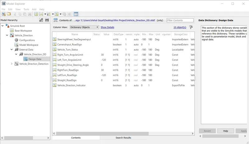
Fig 5 - sldd File after making all entries
2. Model Settings -
- In the model settings, Solver Configuration and Code Generation setting is configured.
- In the Solver Configuration, the solver is set to Fixed Step Discrete solver.
- The Step Size is given as 0.01 as provided in the Required Document.
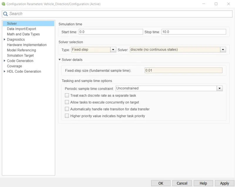
Fig 6 - Solver Setting
- In the Code Generation settings, the Embedded Coder file ert.tlc is selected as System Target File.
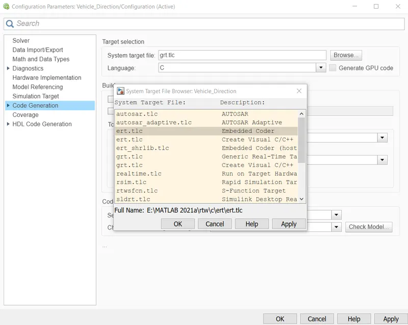
Fig 7 - Code Generation Settings
3. Development of Model -
- As provided in the Required Document, the Input Signals are SteeringWheel_YawDegreeInput and CameraInput_RoadSign.
- The Output Signal is Vehicle_Direction_Indicator.
- A Subsystem is created to implement the required logic.
- This Subsystem is named as Vehicle_Direction_Detection.
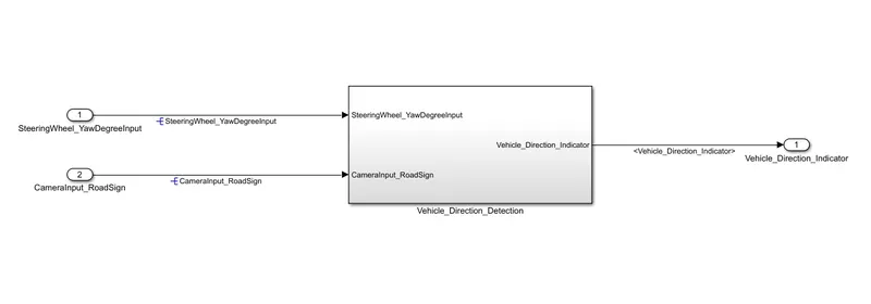
Fig 8 - Model for Vehicle Direction Detection
- In this subsystem, the input and output signals are same.
- For each Requirement a separate Subsystem is created and name of subsystem is given as requirement number.
- For this model, Two requirements are given so two subsystems are created.
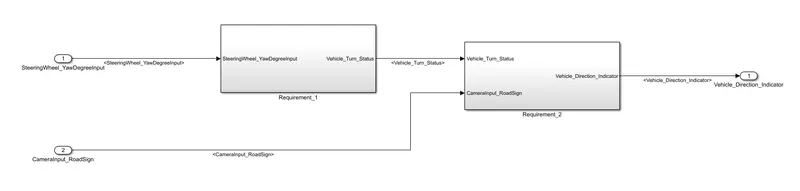
Fig 9 - Subsystem for each Requirement
- For Requirement 1 -
- Steering wheel input as yaw rate (Signal name: SteeringWheel_YawDegreeInput) is the input for this system.
- This is compared against 3 angular values, one each for left turn, right turn & straight drive (Calibration Values: Right_Turn_AngularLimit, Left_Turn_AngularLimit, Straight_Drive_Steering_Angle) to say which specific direction the steering wheel is turning towards.
- Switch blocks are used to compare values.
- The output of this requirement is a local signal (Signal Name: Vehicle_Turn_Status).
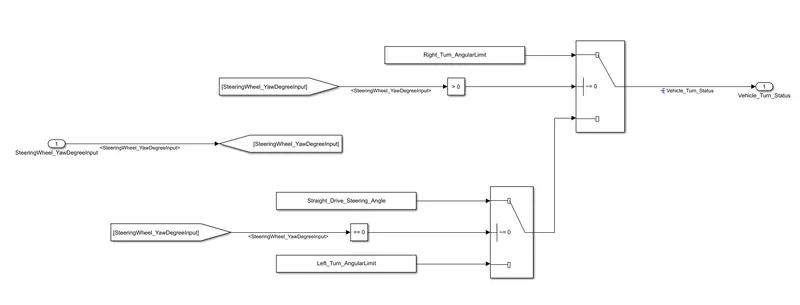
Fig 10 - Requirement 1 Logic
- For Requirement 2 -
- Inputs to this requirement are local signal from requirement 1 (Signal Name: Vehicle_Turn_Status) & an input signal from camera (Signal Name: CameraInput_RoadSign), which confirms the occurrence of a road sign.
- Signal Vehicle_Turn_Status is compared against calibration values (Calibration Values: RightTurn_RoadSign, LeftTurn_RoadSign, Straight_RoadSign).
- If each of them is found equal, then each of the three corresponding output is compared against the camera input signal using Logical AND Block.
- The output of this signal is model output signal (Signal Name: Vehicle_Direction_Indicator).
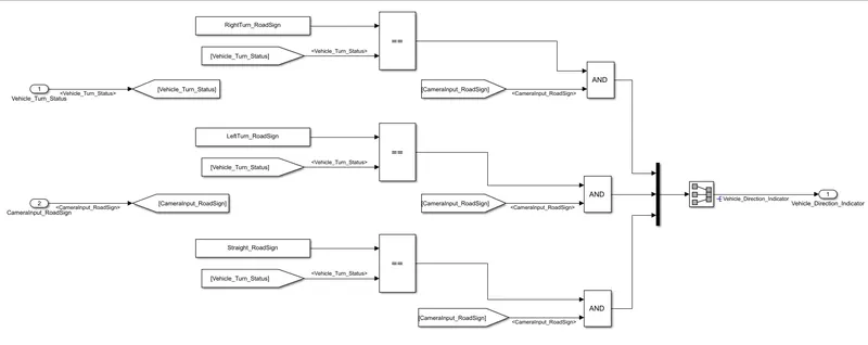
Fig 11 - Requirement 2 Logic
- A Signal Conversion Block is used between Mux and Outport.
- It is used in Signal Copy Mode.
4. Signals Tagging -
- The signals that are present in sldd file are need to named and tagged in the model.
- When the signal is originated, this signal need to be Resolved.
- When the resolved signal goes into different subsystem it needs to be Propagated.
- It can be done either using Property Inspector or Right click the Signal and select Signal Properties.
- To resolve the signal, select the signal.
- In the Property Inspector, give the name of the signal and check the box "Signal name must resolve to Simulink signal object".
- A blue colour symbol will appear in front of Signal name after resolving as shown in Fig 12.
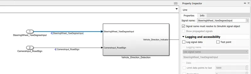
Fig 12 - Signal Resolving
- As this signal goes into the subsystem it is needed to propagated because one signal is resolved for only one time at the point of origination.
- To propagate the signal after resolving, select the signal.
- In the Property Inspector, tick the second check box "Show Propagated Signal".
- This Propagated Signal show between < > symblos.
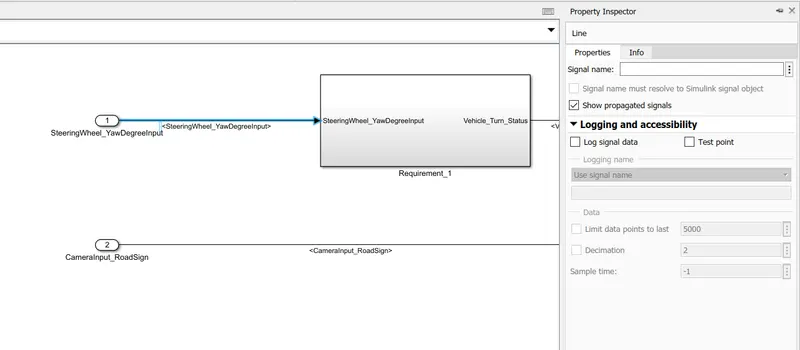
Fig 13 - Propagated Signal
- This resolving and propagation is done for all signals present in sldd file.
Requirement Tagging -
- The Requirement Tagging is linking the model with the description present in the Requirement Document.
- This tagging is done for both the requirement subsystem.
- To Tag the subsystem, select the description in Required Document which has to linked with the model.
- Right Click the subsystem.
- Select the Link to Selection in Word in the Requirements Options.
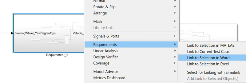
Fig 14 - Requirement Tagging
- The link is created.
- To check the link created, again right click on subsystem and go to Requirements options.
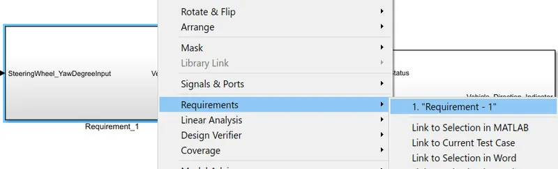
Fig 15 - Requirement Tag
- This tagging is done for all the requirement subsystem created.
Model Advisor Check -
- To check the model developed is up to par with Modelling Standards for MAB.
- To run this check, go to Modelling Tab.
- Open Model Advisor.
- Select the whole system in the System Selector.
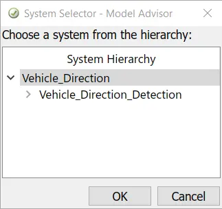
Fig 16 - Model Advisor System Selector
- Model Advisor Dialogue Box will Open.
- In this Advisor menu, uncheck all the check boxes and expand the By Task Option.
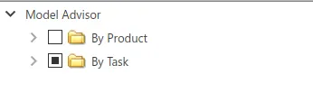
Fig 17 - Model Advisor Checks
- In this select only Modelling Standards for MAB.
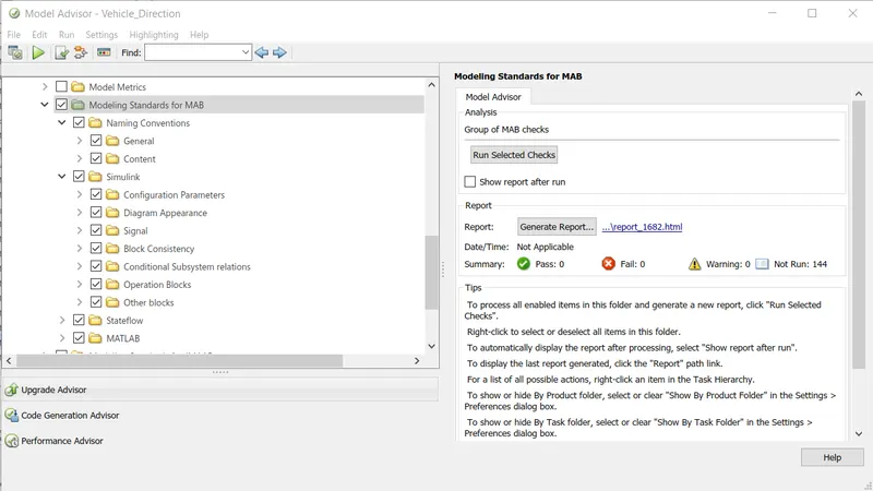
Fig 18 - Modelling Standards for MAB
- This contain a total of 144 checks.
- Click on Run Selected Checks.
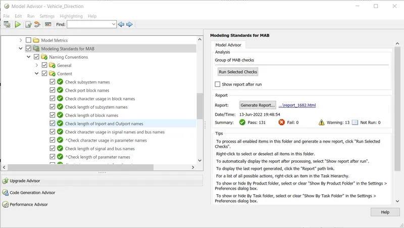
Fig 19 - Model Advisor MAB conditions Checks
- For the model developed out of 144 checks, it passes 131 checks and the remaining 13 checks are warnings.
- The number of warnings can be reduced by clicking the checks containing yellow exclamatory mark.
- In the description of the selected check, cause of warning and its redeemption is given.
- Follow the instructions and try to reduce as much warnings as possible.
- After removing all possible warnings, again run the checks with warning sign.
- It will show the pass green mark.
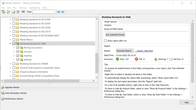
Fig 20 - MAB Analysis after Removing all Possibe Warnings
- After removing all possible warnings, th e number of warnings reduced to 7.
- After this Generate Report for the Checks Done in Model Advisor by clicking Generate Report Option.
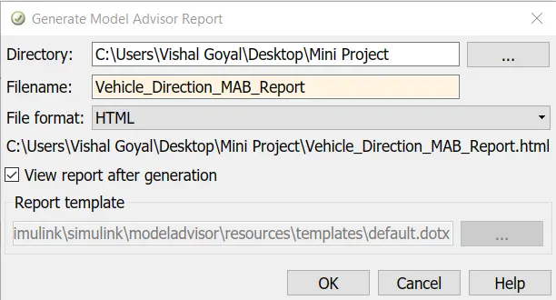
Fig 21 - Model Advisor Report Generation
- Provide Name and Directory Path in Model Advisor Report Generation Dialogue Box.
- This will generate the report.
Code Generation -
- For the model developed C code is generated to provide it to the Electrical Control Unit (ECU).
- To generate the code, in the Apps tab select the Embedded Coder.
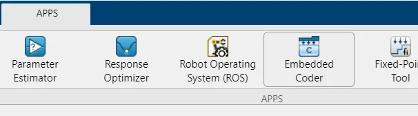
Fig 22 - Embedded Coder in Apps Tab
- Select Build Option to generate the C code for the developed model.
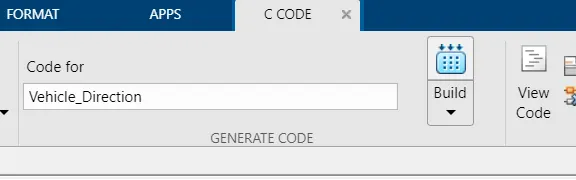
Fig 23 - Code Generation
- When the code is generated select View Code option to open the generated code file.
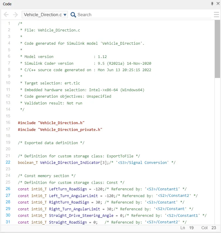
Fig 24 - Generated C Code
Model in Loop (MIL) Test -
- The Model in Loop (MIL) Test is done to test the mathematical model developed whether provides the expected output or not.
- A Test Harness is generated for the Test.
- To generate a test harness, select everything between inports and outports and create a subsystem.
- Right Click the subsystem, select Create for Subsystem option in Test harness.
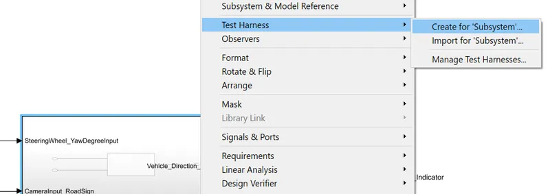
Fig 25 - Test Harness Creation
- In the Test Harness Creation window, for the Source Signal Builder is selected and rename the test harness as MIL_Test_Harness.
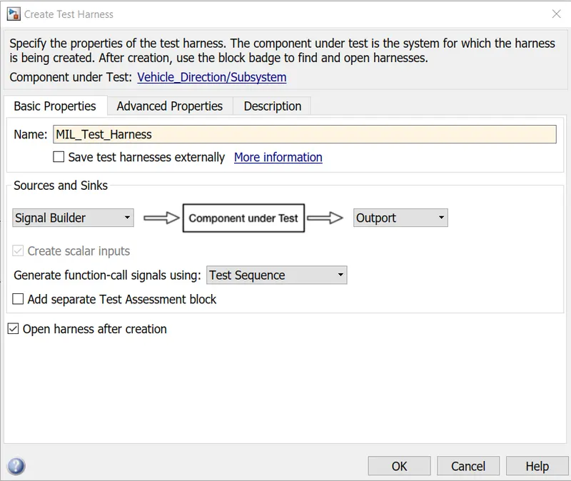
Fig 26 - MIL Test Harness Creation
- In the Advanced Properties, for MIL test Verification Mode is set to Normal.
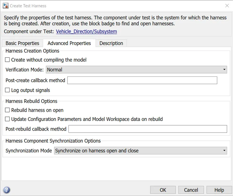
Fig 27 - Test Harness setting for MIL Test
- The MIL Test Harness generated is shown below
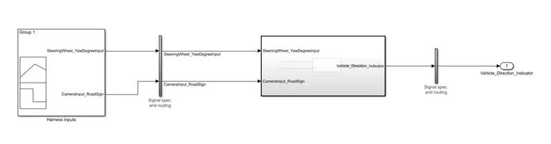
Fig 28 - MIL Test Harness
- In the Signal Builder provide the Test Case.
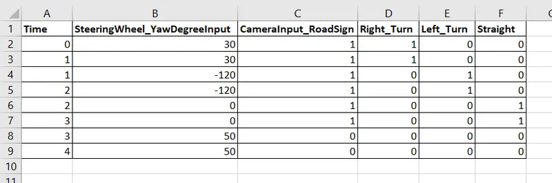
Fig 29 - Test Cases for Signal Builder
- In the Signal Builder, using the Import from File option Test Cases are imported from Excel File.
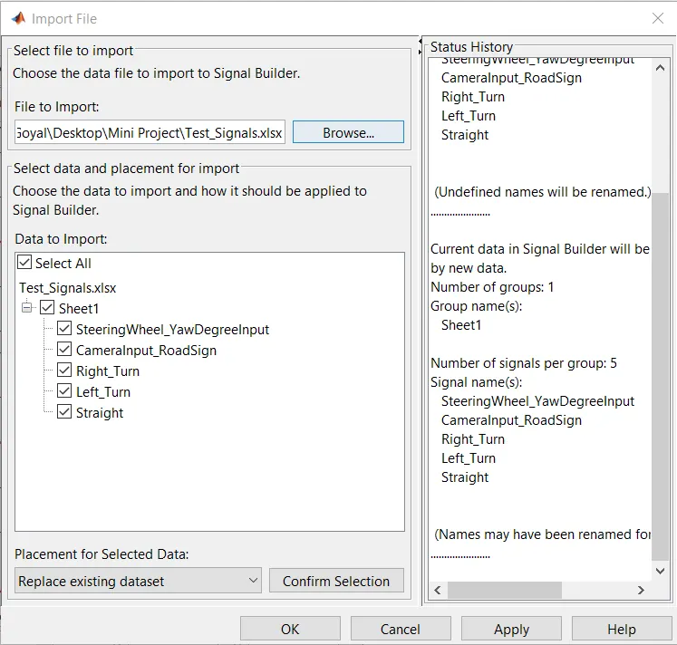
Fig 30 - Import Data in Signal Builder
- Select all in Data to Import section and Choose Replace Existing Dataset.
- The Signal Builder will import the test cases data.
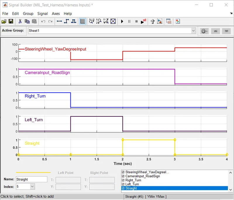
Fig 31 - Test Cases Data in Signal Builder
- To verify the output obtained is as expected or not, connect three subtract block and scope after seperating the signals using Demux and connect output signal and signal builder input.
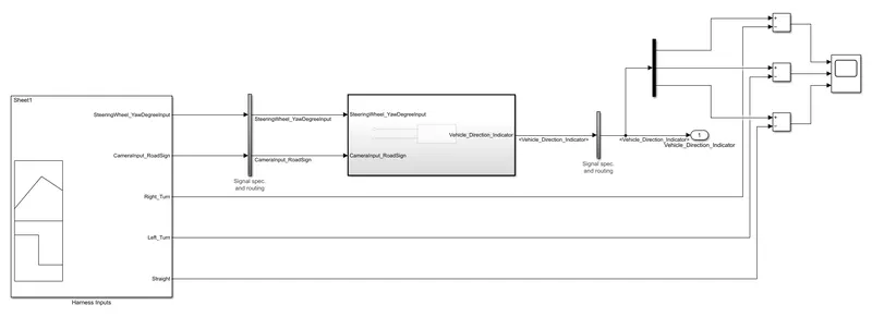
Fig 32 - MIL Test Model Verification
- After running the simulation the scope should show zero if obtained output is same as expected output.
- The scope shows zero for all three signals.
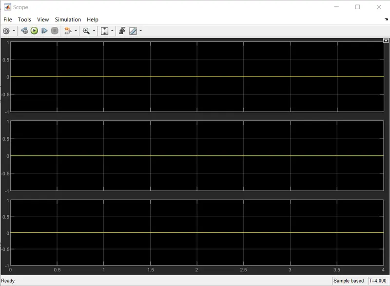
Fig 33 - Scope Result for MIL Test
Software in Loop (SIL) Test -
- The Software in Loop Test is conducted to check the C Code generated produces output as required.
- The process to create Test Harness is same as in MIL Test.
- In the Test Harness menu, select Signal Builder as Source and rename the Harness as SIL_Test_Harness.
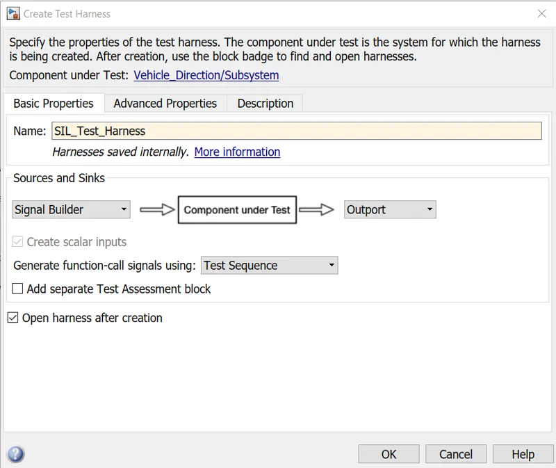
Fig 34 - SIL Test Harness Creation
- In the Advanced Properties settings, select Software in Loop in the Verification Mode.
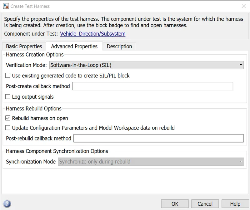
Fig 35 - Test Harness Setting for SIL Test
- The SIL Test Harness will open as shown
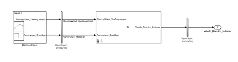
Fig 36 - SIL Test Harness
- The signal builder data is imported from the test cases excel file as done in MIL Test.
- To verify the the results output signals are separated using Demux and subtract blocks are connected to them and signal builder and a scope is used to check the results.
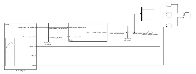
Fig 37 - SIL Test Model Verification
- After running the simulation scope difference beween signal builder signal and outpu signal should be zero.
- The scope shows zero which means the output obtained is the expected output.
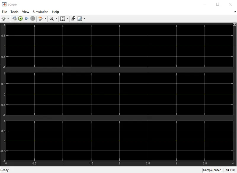
Fig 38 - Scope Result for SIL Test
Conclusions -
- The Vehicle Direction Detection is successfully developed according to the MAB guidelines.
- The creation of Data Dictionary File and Requirement Tagging is successfully done.
- The signals are resolved and propagated successfully.
- The C Code is generated for the model successfully.
- The MIL and SIL Test are performed without any errors.
Google Drive Link for Project Folder - Project_Vehicle_Direction_Detection