Project 1 (Mini Project on Vehicle Direction Detection
A vehicle direction determination model is created using MATLAB Simulink as per the requirements given. Firstly a blank model is created to which a data dictionary is linked. This SLDD file is defined using the given parameters as shown in the figure below.
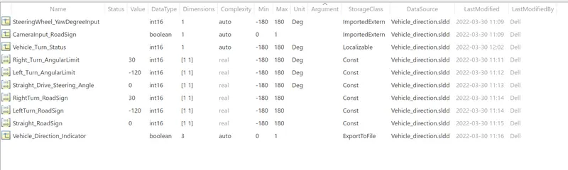
Based on the conditions given, all inputs are set to ImportedExtern, all outputs are set to ExportToFile, constants are set to Const and local signals are set to localizable storage classes. The minimum and maximum values are set as per the given data.
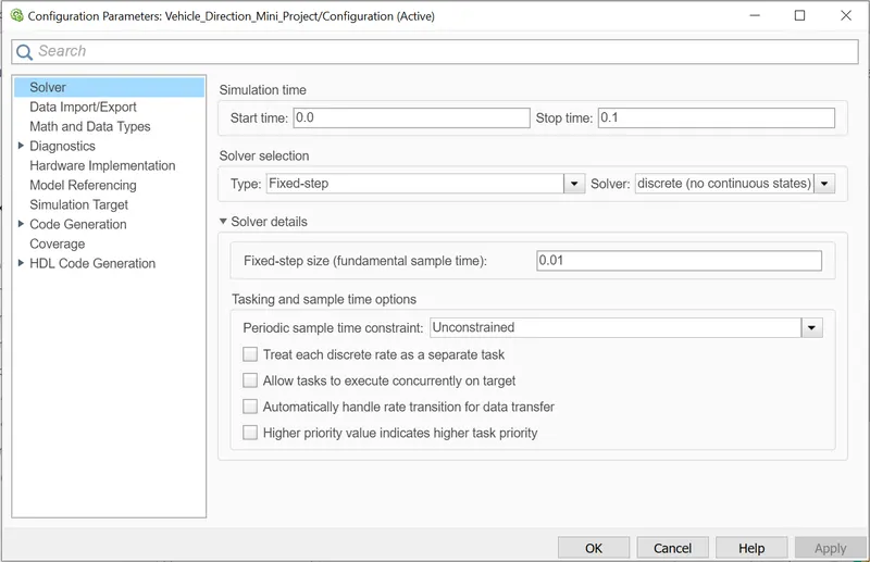
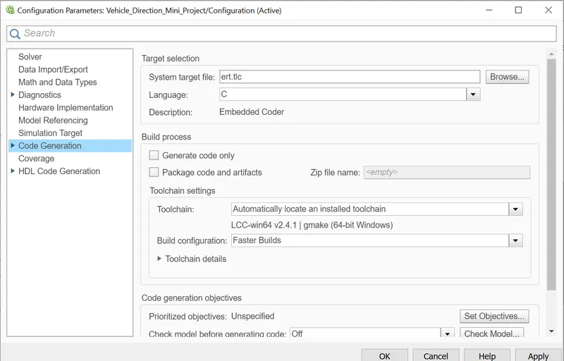
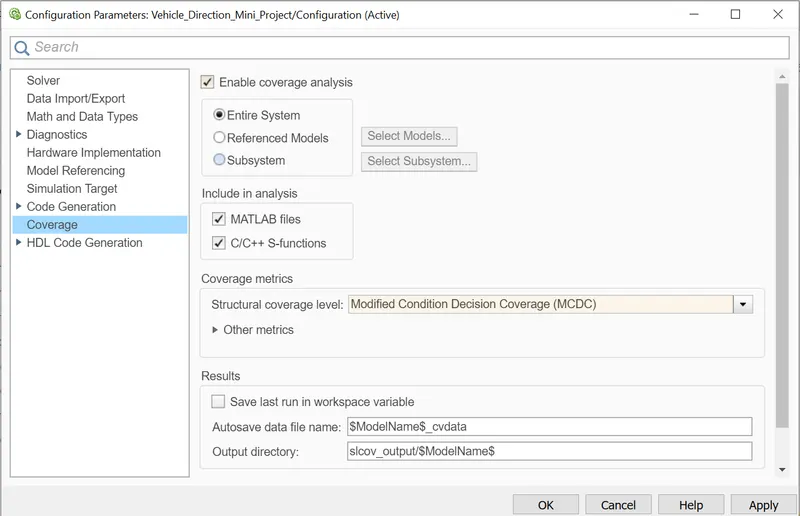
The configurations of the model are set under the model settings tab. Solver is set discrete fixed type. The code is generated using an embedded coder. The coverage is enabled and is set to modified condition decision coverage.
Now the model is created by creating a primary subsystem, inside which two sub systems are created for two requirement models.
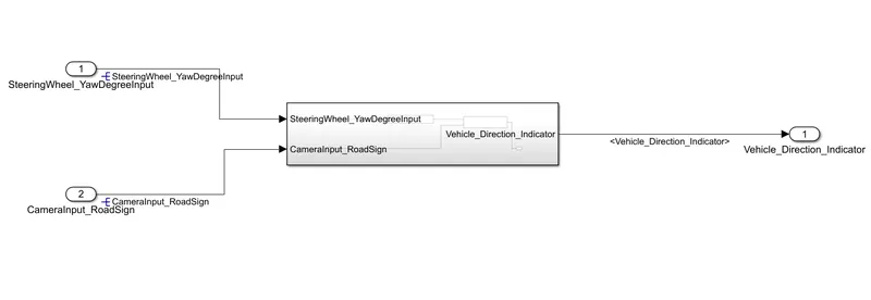
The SteeringWheel_YawDegreeInput and CameraInput_RoadSign are the input to the main subsystem, vehicle direction indicator acts as the output of the model.
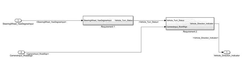
The steeringWheel_YawDegreeInput acts as the input for requirement 1 subsystem, CameraInput_RoadSign and the output of requirement1 vehicle turn status acts as the input of requirement 2 subsystem.
The Requirement 1 subsystem consists of relational operators and a switch to perform the operations as per the data.
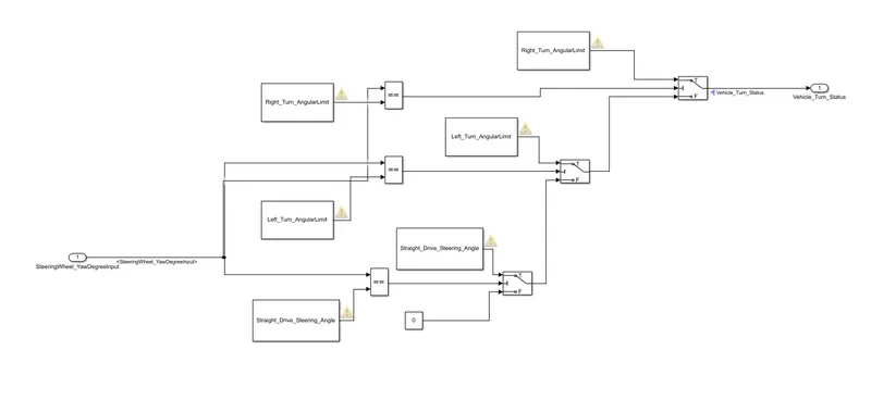
The SteeringWheel_YawInput is compared with Right_Turn_AngularLimit value, If it is equal then, Vehicle status will be Right_Turn_AngularLimit Value. If not the value is compared with Left_Turn_AngularLimit value. If the value is equal,the latter value is sent to the output. If the input value is not equal, It is compared with Straight_Drive_Steering_Angle. If the value compared is equal that value occurs at the output. If the comparison is false, 0 constant value occurs at the output.
This value acts as the input for the requirement 2 subsystem.
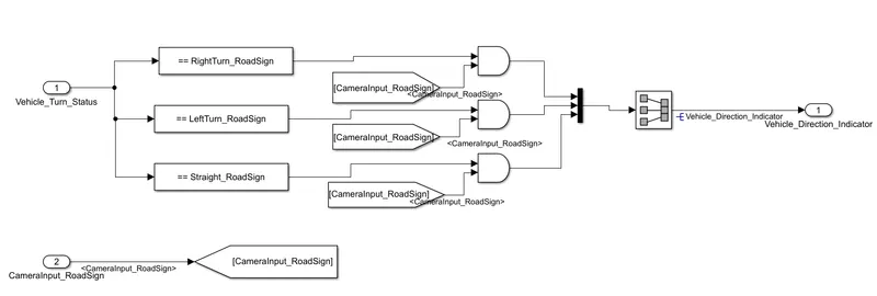
The vehicle turn status is compared with the camera input value and a vehicle direction indicator is sent as the output when compared with RightTurn_RoadSign, LeftTurn_RoadSign and Straight_RoadSign respectively.
The from and goto blocks, Compare to constant blocks are used for modeling this system.
All these signals are resolved and propagated throughout the model to reduce confusion and to use efficient modeling technique.
With Model Advisor Tool, The rules are checked and tested. If in case there are any errors it can be resolved, warnings can be corrected by performing this check.
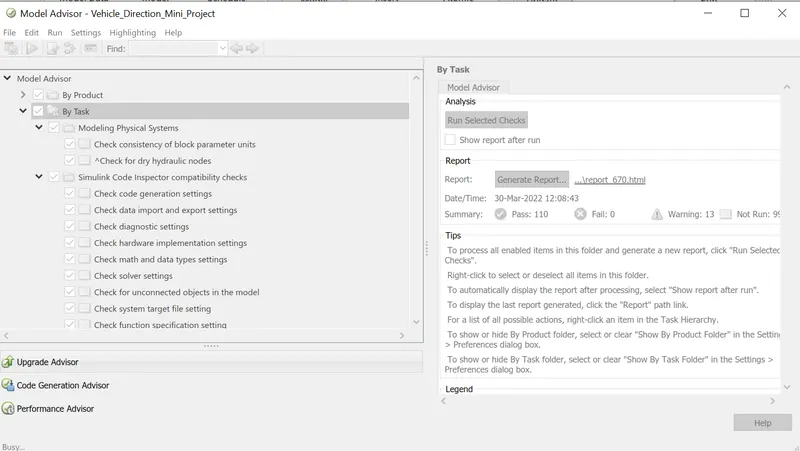
All the tests are checked and Run Selected Checks option is selected.
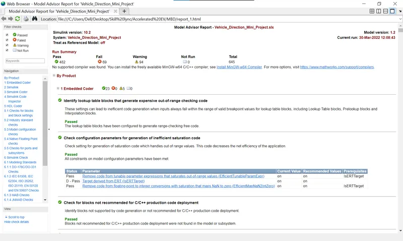
And a report is generated based on the results from this test.
Under APPS, Embedded Coder, we can generated the firmware for this mini project. This code can be saved and used in the controller.
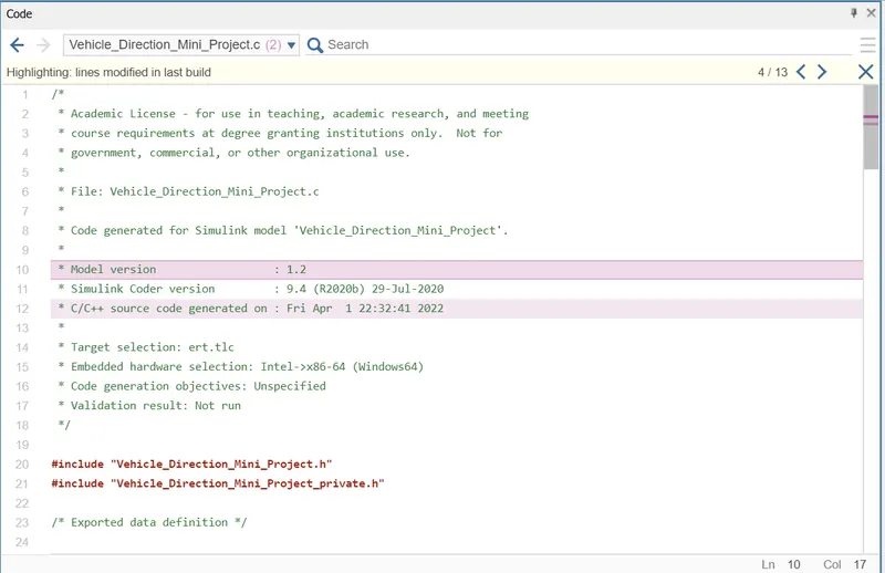
With also these steps the model is developed, tested, executed and, generated C code.