Project 1 (Mini Project on Vehicle Direction Detection
SOLUTION :
Objective of Mini Project:
- Development of MATLAB Simulink model as per requirement
Signals & Calibration Data List:
|
Signal / Calibration Name |
Signal Type |
Data Type |
Dimension |
Min |
Max |
Initial Value |
Units |
|
SteeringWheel_YawDegreeInput |
Input |
Int16 |
1 |
-180 |
180 |
- |
Deg |
|
CameraInput_RoadSign |
Input |
Boolean |
1 |
0 |
1 |
- |
- |
|
Vehicle_Turn_Status |
Local |
Int16 |
1 |
-180 |
180 |
- |
Deg |
|
Right_Turn_AngularLimit |
Calibration |
Int16 |
[1 1] |
-180 |
180 |
30 |
Deg |
|
Left_Turn_AngularLimit |
Calibration |
Int16 |
[1 1] |
-180 |
180 |
-120 |
Deg |
|
Straight_Drive_Steering_Angle |
Calibration |
Int16 |
[1 1] |
-180 |
180 |
0 |
Deg |
|
RightTurn_RoadSign |
Calibration |
Int16 |
[1 1] |
-180 |
180 |
30 |
|
|
LeftTurn_RoadSign |
Calibration |
Int16 |
[1 1] |
-180 |
180 |
-120 |
|
|
Straight_RoadSign |
Calibration |
Int16 |
[1 1] |
-180 |
180 |
0 |
|
|
Vehicle_Direction_Indicator |
Output |
Boolean |
1 |
0 |
1 |
- |
- |
Development of the Model :
The model in the figure given below is the main model of our Vehicle Direction detection model .
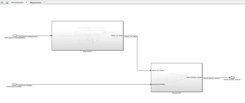
We have given here 2 inputs according to our requirements, which are SteeringWheel_YawDegreeInput and CameraInput_RoadSign. We will have to resolve these 2 signas here , because this is where the signals have appeared for the first time in our project . From the Signal Settings we can resolve it easily . The following image illustrates it better .
According to the given condition , these signals are used to detect and confirm the presence of the road signs with the help of a camera , which is interpreted by one of the inputs used , CameraInput_RoadSign as Right Turn , Left Turn or Straight Drive . When the driver takes the direction then a corresponding a final feedback will be given to the driver if has taken the correct direction required or not . An output signal is used Vehicle_Direction_Indicator , which is a boolean type value , which specifies whether the vehicle is turning right , left or straight .
We have the main subsystem here named as Vehicle_Direction . We have two more subsystems inside this main subsystem which are used to follow up with the 2 requirements we are provided with in the question . , namely Requirement1 and Requirement2 .
The first subsystem will be as follows :
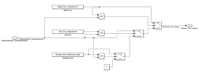
Here we are feeding the SteeringWheel_YawDegreeInput and comparing with the three Direction limits, Right_Turn_AngularLimit, Left_Turn_AngularLimit and Straight_Drive_Steering_Angle . This is then given to a switch and then finally we are getting the Output as Vehicle_Turn_Status . This output will be fed into the 2nd subsystem 'Requirement2 ' .
The second subsystem willl be as shown in the below diagram :
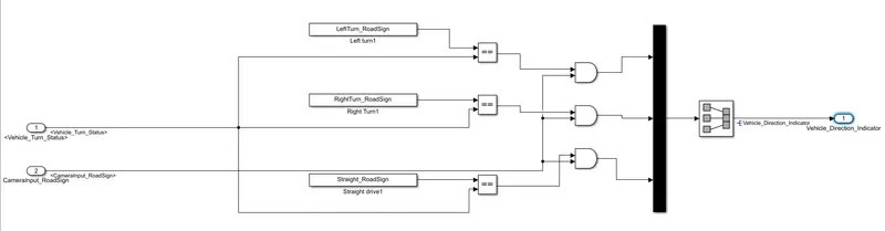
The output from the first subsystem and the other input , CameraInput_RoadSign is also fed as inputs into the second subsystem . We have three Calliberation values given . So this Vehicle_Turn_Status is compared here with these constants : RightTurn_RoadSign, LeftTurn_RoadSign, Straight_RoadSign and if it is found equall then we do an operation with AND gate and find output for each Directions . Only if it is true the output will be set and then fed into a MUX block. Then output through a Signal conversion block is fed into the Output , which is the Vehicle_Direction_Indicator.
Now we have all the signls and parameters given to us , which we have added in the sldd file .So we will have to resolve the signals and propagate it respectively according to its order of appearance in the model .
The following dialog box shows how we resolve a signal .

The signal SteeringWheel_YawDegreeInput is resolved initially before it gets to the subsystem 1 , because that is where it appears for the first time in the model .
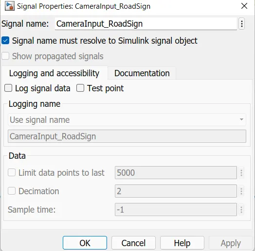
Similarly we make all the signals resolve by getting into the right place . Then we propagate the signals appropriately .
Then we change the Solver Settings from the Model Settings from Variable Step Solver into Fixed Step Solver .Sample time is changed to 0.01 and the type is discrete .In the Code Generation we change the Target file from grt.tlc to ert.tlc .
These details are added into the Simulink Data Dictiinary which is created as 'vehicle1.sldd' :
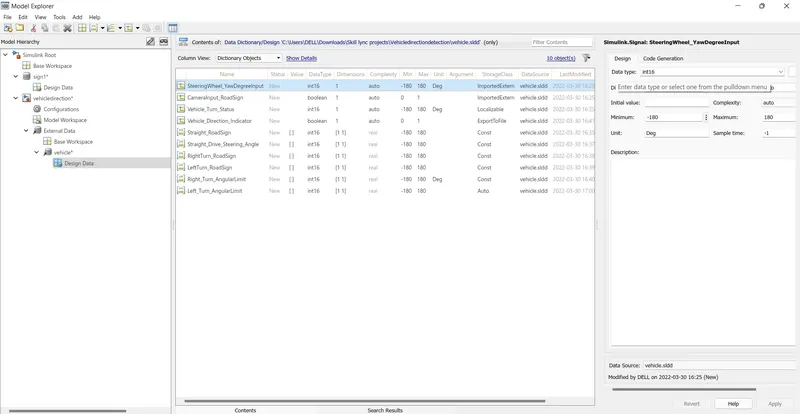
The input signals are given the storage type ImportedExtern and output signals as ExporttoFile. Local signals are given Localizable . Sample time for each signal is given as 0.01 Seconds .
For the Constant Simulink Parameters in the Code generation settings of sldd we change the header file and definition file to :
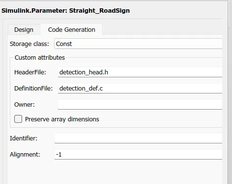
Next we goonto tagging the Requirements file . For that we convert the question given here into a word document and do the necessary highlighting and tagging it under the requirement section .
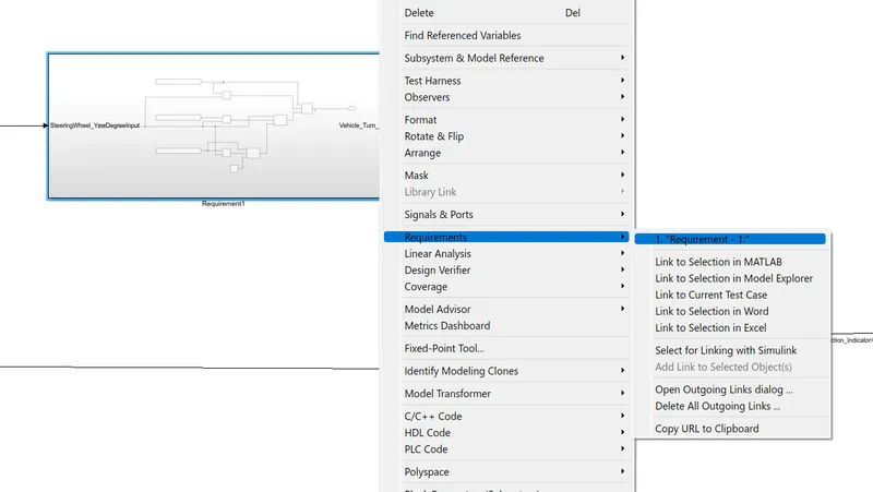
This is how it looks on tagging a requirement file .
Now , next we go with the model advisor check , for this we go to the Model Settings and then Model Advisor is selected .
From this we select our required model to check .
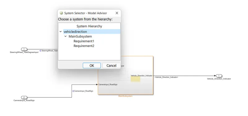
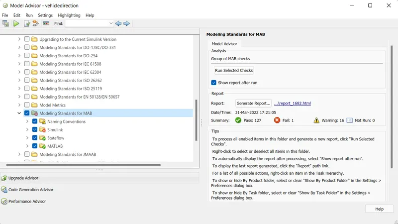
The Model Advisor report has also been generated . That is attached with this answer .
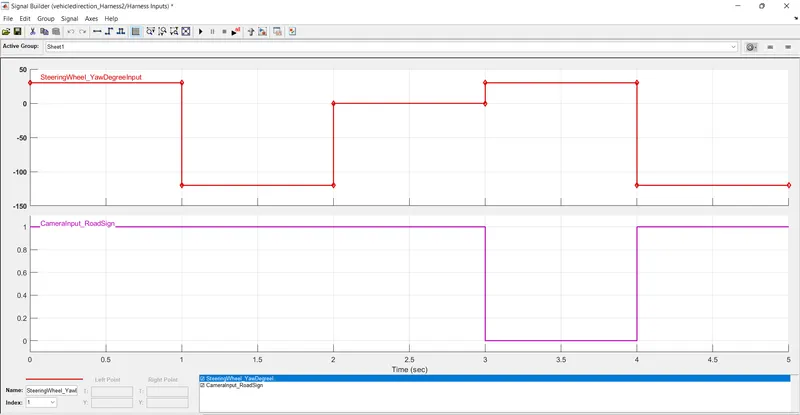
Now we carry out the MIL Test here . For that we does the test harness and make the source as Signal Builder .
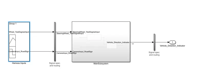
So now we have to write Test Cases for the same .
So the Model is created successfully and also the MILTest is done .