Project 1 (Mini Project on Vehicle Direction Detection
Objective:
- Simulink model to be developed for vehicle direction.
- Sldd file to be created
- And requirement tagging has to be done.
Study/:
- Sldd file has to be created and following data to be added in it.
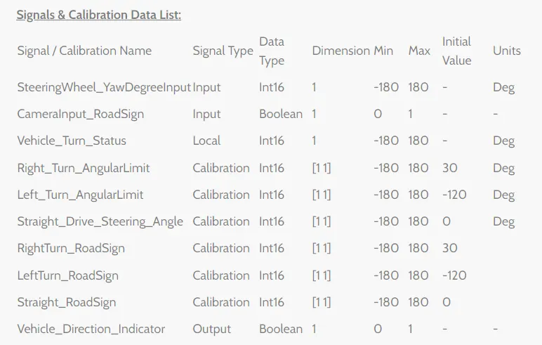
sldd file:
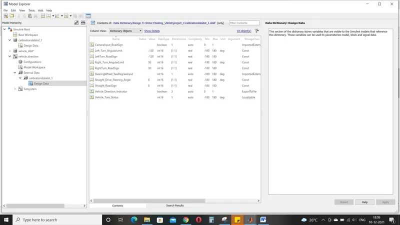
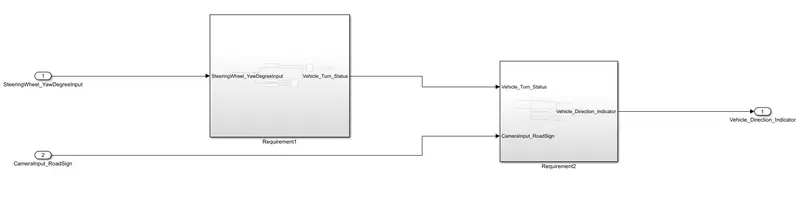
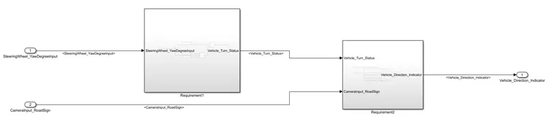
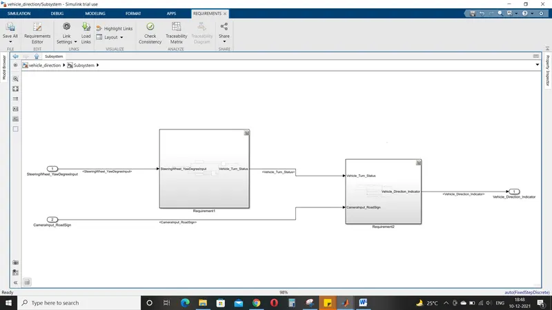
- The simuink model as 2 requirement and below image is the subsystem of requiements
- The 2 input signal are connected to the subsystem and a output signal i.e vehicle direction indicator

- As shown below inside the subsystem 2 requirement subsystem are developed
Requirement 1:
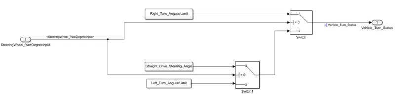
- Requirement1 is developed based on the objective.
- Three angular values are assigned in sldd file so the same is implemented using constant block.
- These 3 angular values are compared with input signal (steering wheel yaw degree input) and using the switch block the comparison is made.
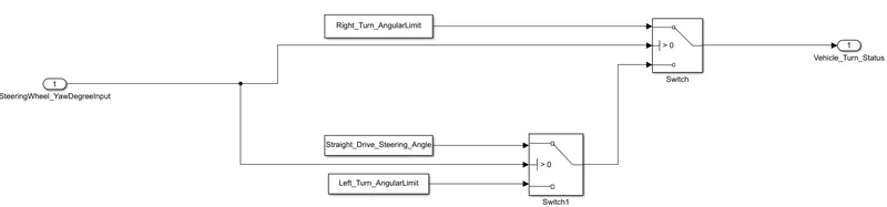
- The output of these is the resultant vehicle turn status
Requirement2:
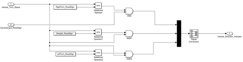
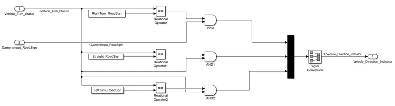
- In the requirement2 ; we have provided 3 calibration values and this values has to be compared with 2 input signals.
- Signal Vehicle_Turn_Status is compared against calibration values , if each of them is found equal, then each of the three corresponding output is compared against the camera input signal.
- And comparison is done with using logical operator 'AND' block
- One input signal is taken from the output of the requirement1 subsystem and the other is the camera input read sign.
- Now the input and output signals has to be compared
- This can be done by selecting the connecting signal
- select connecting signal->properties->click on it
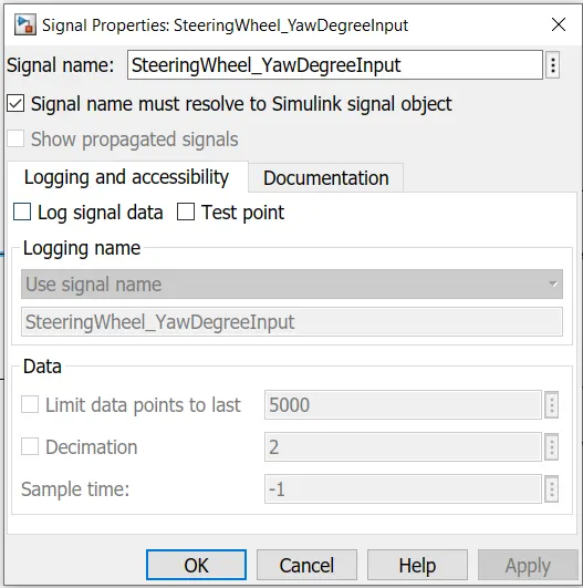
- In the signal properties , we need to give the signal name and click on ->signal name must resolve to simulink signal object ->ok
- And to propogate the signal
select the connecting signal ->properties -> click on show propogated signals->ok
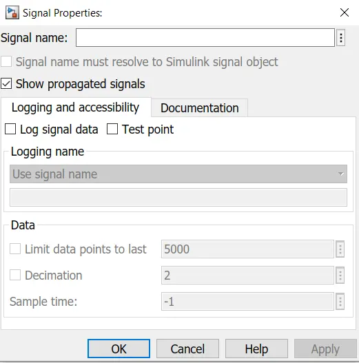
The below are imgaes of the signals resolving and propogated .
The signals are propogated in the 2 requirements and resolved wherever required
Requirement tagging:
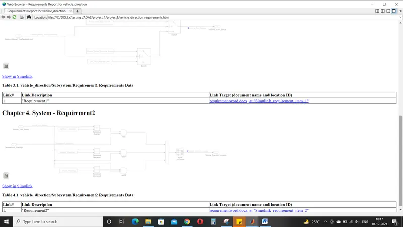
- The requirement tagging is done for both the subsystems
- Word document to be created as shown for both the requirements
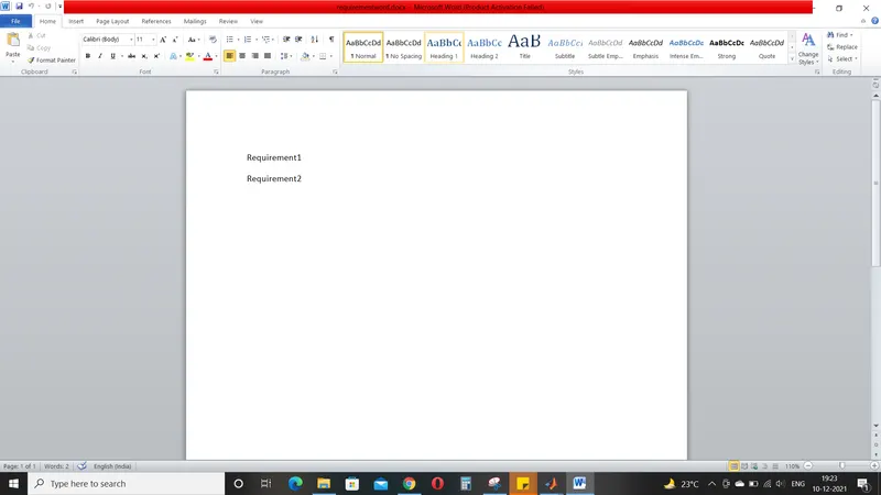
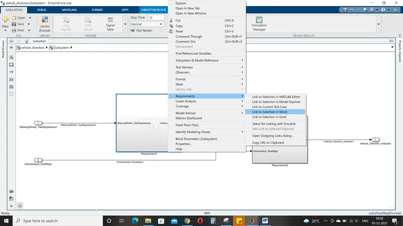
- Select the requirement1 in the word document and click right click on the subsystem , click on the requirement to link the word to the requirement1 as shown
- After linking the word doc ; the model is displayed as shown
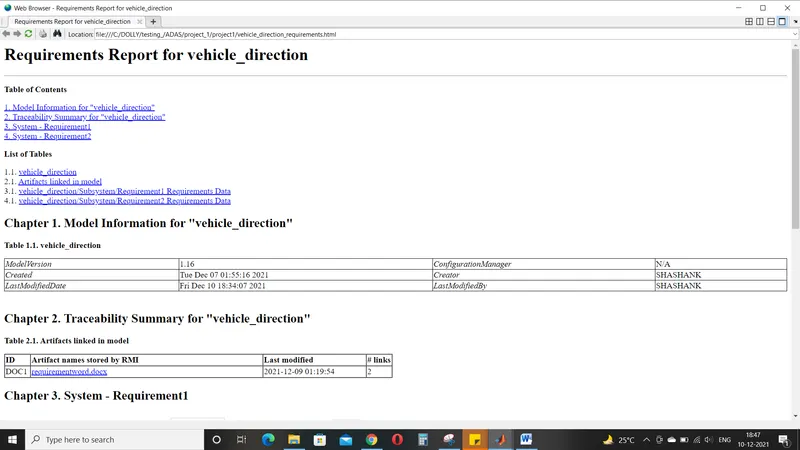
- In the requirements we need to generate the tracebility report by click the share option beloow the requirements
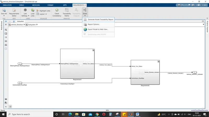
- The tracebility report is generated as shown below for both the requirements.