Project 1-Meshing of Rear Wheel Holder challenge
Objective: Objective of this challenge is to create the mesh with required quality parameters, after extracting the mid surface of the given model
Procedure:- To start working with the model, first we will import the given 3d file into the hypermesh working window, using the import option.
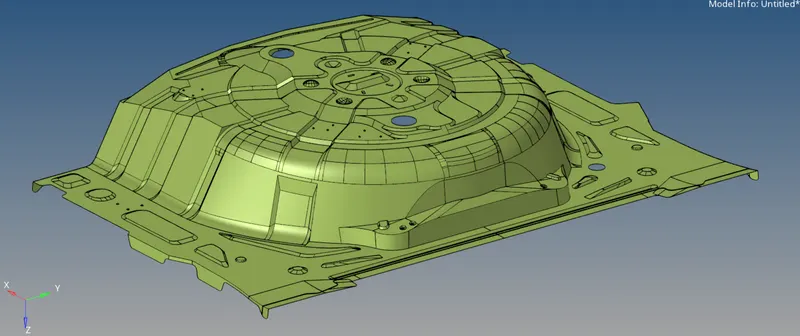
Figure 1: Showing the imported 3D file in hypermesh
After importing we will look for the geometrical errors in the part, by switching the view option to topo view. Here, we will look for the inappropriate single, double or tripple edges.
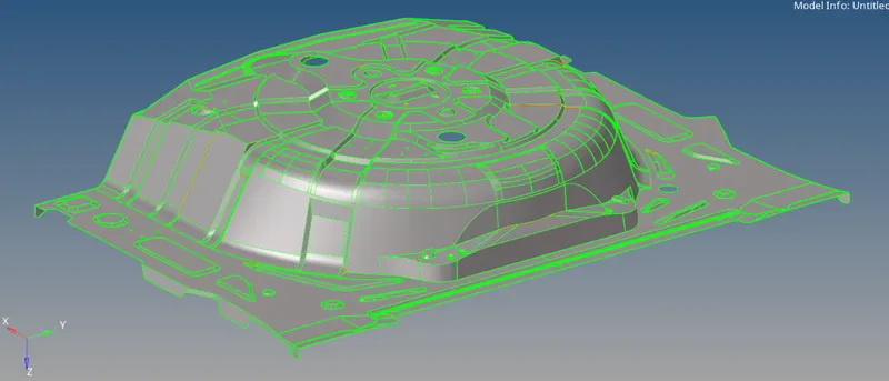
Figure 2: Image showing model in topo view
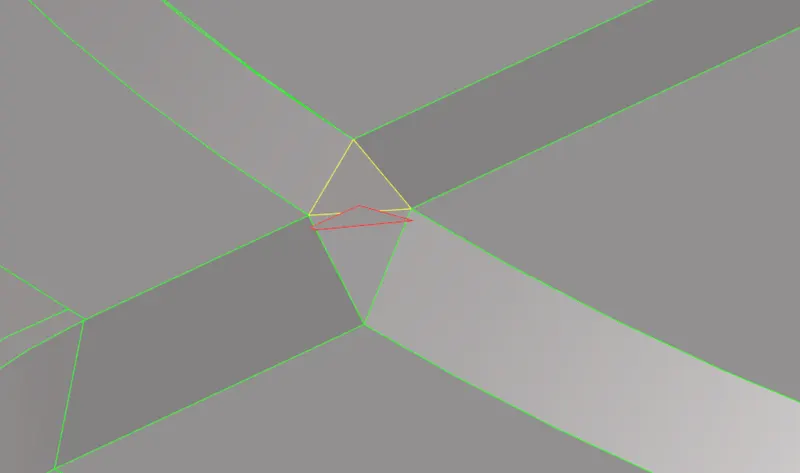
Figure 3: Showing inexact edges
Before extracting the mid surface, first we will fix all the in-exact edges and remove all the unwanted features from the model.
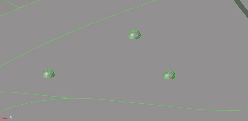
Figure 4: Showing all unwanted features
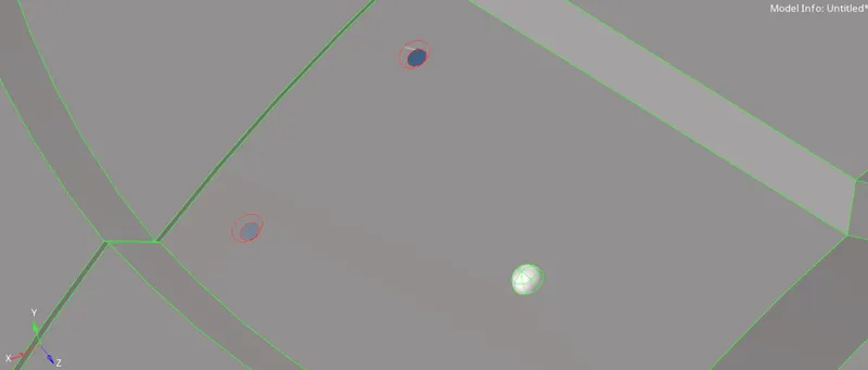
Figure 5:Showing the fixing of unwanted features
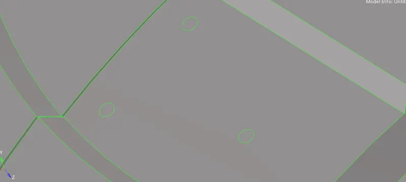
Figure 6: Showing clean geometry
After fixing all the geometrical errors and simplifying the geometry, we will extract the mid surface of the model. Since, it's a complicated part, with non-uniform thickness across the edges, the auto mid option will not give the best results. So, we will use the manual offset option to extract the mid surface of the model.
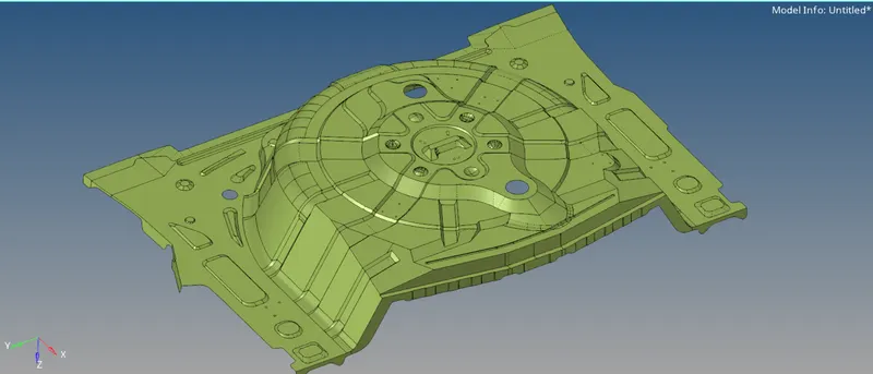
Figure 7: Image showing extracted mid surface
There were some errors in the extracted mid surface, that need to be fixed before starting meshing. That errors will be fixed by using various commands available in geom section, by deleting irregular surfaces, creating new ruled surface, or by filler surface. There will also be the use of toogle edges to make the geometry clean and improve the mesh flow.
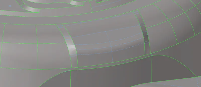
Figure 8: Image showing suppressed lines to improve the mesh flow.
Now we will add the quality parameters according to which the mesh will be created.
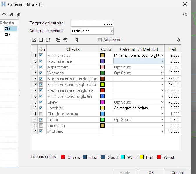
Figure 9: Showing the quality parameters setting window.
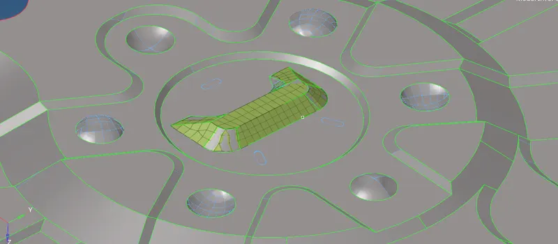
Figure 10: Showing mesh creation from center surface.
To obtain the good mesh flow, we will start creating the mesh from the center surface and then gradually moves towards outer surfaces.
At the same time we will also monitor the mesh quality of the created surfaces, to obtain good mesh flow. this can be done by setting the view option to mesh quality.
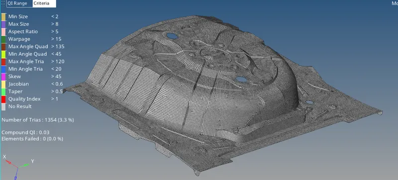
Figure 11: Image showing the mesh quality index for the created mesh.
After crating the mesh for all the surfaces, and fixing the quality, the model will be ready for the furthur proceddings. Now, the other important task is to create the material, which will be done by creating the new material in the tree. In this challenge, i have used the ABS for the material.
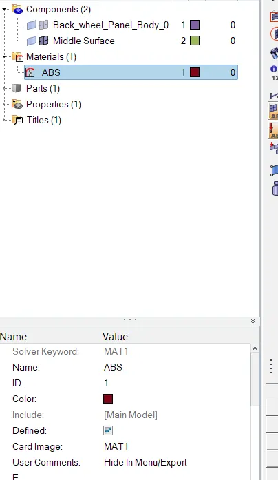
Figure 12: Image showing created material with it's name and property.
Now, we will create a new property named PSHELL in which we assign the thickness value. and after that we will assign this property to the middle surface which we have created earlier. This will give the thickness to the shell elements of the mesh.
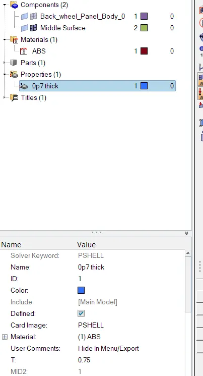
Figure 13: Showing created PSHELL property, with material and thickness assigned.
After assigning this property to the mid surface, our model is finally ready for applying boundary conditions.
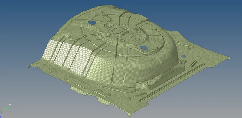
Figure 14: Showing final image of the ceated mesh.