Project 1-Meshing of Rear Wheel Holder challenge
Meshing of Rear Wheel Holder challenge
Aim:
- To pre-process the Rear Wheel Holder (Spare Wheel Floor Panel) Sheet Metal component using HyperMesh.
Objectives:
- Manually extract the mid-surface and perform geometry clean up on the component.
- Generate a mesh with a smooth flow and minimize Tria element concentration.
- Ensure the mesh meets the specified quality criteria.
- Assign appropriate thickness values to the component.
Phase 1 - Importing the Geometry:
- The first step involves importing the given CAD geometry into HyperMesh.
- Common CAD file formats like IGES, STEP, and Parasolid are widely used in various CAD and CAE software.
- However, HyperMesh supports the import of the following three file formats:
- IGES (Initial Graphics Exchange Specification)
- STEP (Standard for the Exchange of Product Model Data)
- SolidWorks
- IGES and STEP are industry-standard formats that are frequently utilized, though Parasolid has gained popularity in recent years.
- When importing the geometry into the HyperMesh interface, ensure that the file is in either .step or .iges format.
- The process for importing is as follows:
- Go to File > Import > Import Model > Choose the file type > Open the file > Import.
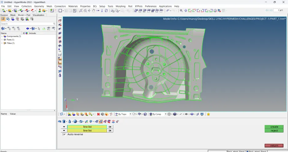
FIG - 1 IMPORTING THE CAD MODEL.
Phase 2 - Examining the Geometry:
- Before starting any work on the model, it is essential to inspect the geometry for potential issues, such as:
- Damaged or corrupted geometry.
- Free edges in areas where they are not required.
- Unnecessary points along lines.
- Incorrect or redundant connections and connectivity errors.
- If free edges are found, they should be resolved in the parent component. Properly addressing these issues ensures that the mid-surface can be extracted without errors or glitches in the geometry.
- Upon inspecting the model, there are 17 components present.
- Organize all relevant components into a single component or delete any unnecessary ones.
- Elements such as lines, surfaces, solids, points, and connectors can be copied or moved into component collectors or groups.
- In this step, we are selecting the desired collectors and organizing them into a single collector.
- To do this:
- Go to Tool > Organize > Collector SubPanel > Switch to Surfaces > Select by Collector > Move.
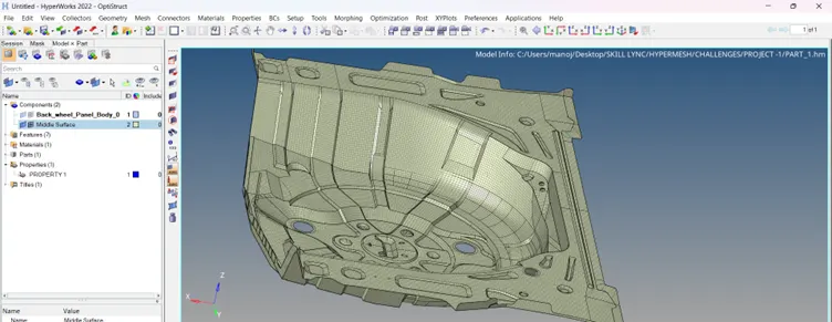
FIG - 2 COMPONENTS ORGANISED
Phase 3 - Geometry Clean-up on the Parent Component:
- Geometry clean-up can be done either on the parent component or after extracting the mid-surface.
Note: It is more efficient to perform the clean-up after extracting the mid-surface, as working on the parent geometry can be time-consuming. Therefore, it's recommended to skip clean-up on the parent component and focus on the mid-surface geometry instead.
Check for Geometric Deformations:
- It is important to inspect the model for any geometric deformations, including:
- Damaged geometry in certain areas.
- Overlapping surfaces.
- Free edges.
- Unnecessary connections such as extra points or lines.
- Connectivity errors.
Fixing Damaged Geometry in Surfaces:
- Deformed surfaces can result from various issues, such as:
- Overlapping surfaces
- Connectivity problems
- Multiple point replacements during editing
- To address these deformations, specific tools can be utilized for efficient repairs.
Note: Avoid replacing points repeatedly. Instead, use surface splitting and proper connections to fix geometry.
Quick Edit Tools can be used to resolve most geometry issues. Below are the available sub-tools and their functions:
- Geometry >> Quickedit >> Split Surface (Node-based):
- Select two nodes to define the splitting line, then choose a third node to extend the surface split further.
- Geometry >> Quickedit >> Split Surface (Line-based):
- Choose a node and then a line; the surface will be split perpendicularly to the selected line.
- Geometry >> Quickedit >> Adjust/Set Density:
- This tool allows you to adjust the mesh density after meshing a surface. By increasing node density, you can improve mesh flow, either before or after meshing.
- Geometry >> Quickedit >> Release Points:
- Select and drag over a surface to release points. After releasing, free edges may appear in those areas.
- Geometry >> Quickedit >> Replace Points:
- This function allows you to move points from one location to another, placing them where needed.
- Geometry >> Quickedit >> Add/Remove Points:
- Use a window selection (with the left and right mouse buttons) to add or remove points within the selected area.
- Geometry >> Quickedit >> Add Points on Line:
- Define how many points you want to add on a selected line and then apply it to the model.
- Geometry >> Quickedit >> Delete Surface:
- Select and remove any surface that needs to be deleted from the model.
These tools help ensure smooth geometry and resolve any deformations or connectivity issues effectively.
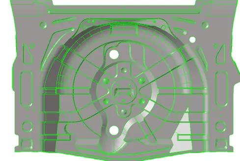
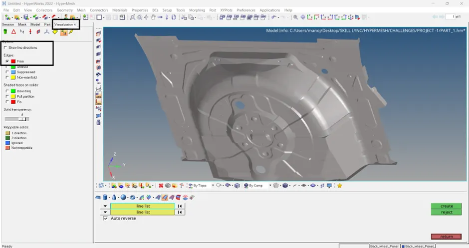
FIG 3 & 4 - GEOMETRY CLEANUP COMPLETED.
Phase 4 - Extracting the Mid Surface:
- The mid-surface is extracted for components with a thickness of less than 6 mm, specifically targeting sheet metal and plastic parts.
Extracting the Mid Surface:
- For this component, I will use the Auto Mid Surface Extraction feature.
- The Auto Mid Surface function allows for the extraction of the mid-surface from complex groups of surfaces that represent a solid part in a single step.
- I am utilizing the Offset + Planes + Sweeps method for extraction, as this component contains multiple features and sweeps.
- The Offset + Planes + Sweeps technique identifies areas where a planar piece or a sweep surface can serve as a mid-surface. In regions where these cannot be applied, a mid-surface is created using the same algorithm applied to the model’s offset sides.
Extraction Steps:
- Navigate to Geom >> Mid Surface >> Auto Midsurface.
- Select the extraction method (Offset + Planes + Sweeps).
- Proceed with Auto Extraction (Closed Volume).
- Ensure the relevant surfaces are displayed and click Extract.
This process will effectively yield the mid-surface needed for further analysis.
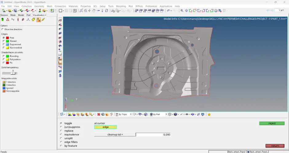
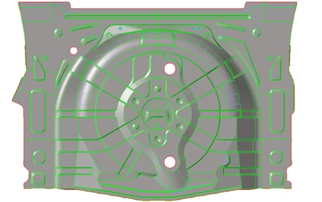
FIG 5 - MID SURFACE GENERATED .
Phase 6 - Performing Mesh on the Surfaces:
- After completing the geometry cleanup—ensuring that surfaces are stitched together and eliminating any unwanted free surface edges within the geometry—the next step is to proceed with meshing.
QUALITY CRITERIA
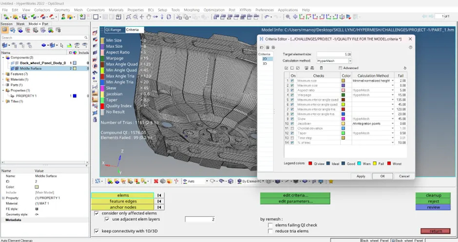
FIG 6 - SETTING UP THE QUALITY CRITERIA
Re-mesh and Rebuild Mesh
Re-mesh:
Remeshing is the process of generating a mesh of plate elements based on surface geometry or existing shell elements that define the mesh area. This process employs the Hyper-Mesh inferred surface algorithm, which requires geometry for the selected elements to be present in the model.
Rebuild Mesh:
Rebuilding the mesh involves remeshing existing meshes to create a new mesh that improves quality and flow. The rebuild mesh functionality uses the same parameter and criteria files employed by Batch Mesher to define quality standards and relevant mesh parameters. This approach saves significant time compared to traditional auto meshing and quality correction methods.
Using Quality Index Cleanup Tools
|
SI. NO |
Tool |
Purpose |
|
1 |
Place Node |
Moves a node along the plane or curvature of the surface or away from the surface. |
|
2 |
Swap Edge |
Cycles through the next valid configuration of an edge each time it is clicked. |
|
3 |
Element Optimize |
Moves the mid-nodes attached to the element being optimized. Enable the "with attached mid-nodes" checkbox for this function. |
|
4 |
Smooth |
Enhances the quality of surface elements. |
|
5 |
Split/Collapse Edge |
To split an edge, left-click on it; Hyper Mesh will divide the elements sharing the selected edge to achieve optimal quality. |
|
6 |
Drag Tria Element |
Click on a triangular element and drag it to a desired location; Hype rMesh highlights the selected tria element in pink. Dragging two trias together can combine them if they face opposite directions. |
|
7 |
Split Quad Element |
Left-click on the quad element you wish to split; Hyper Mesh will divide it into two triangular elements. |
|
8 |
Combine Tria Element |
To merge two triangular elements, left-click on their shared edge; Hyper Mesh will combine them into one quadrilateral element. |
Post-Meshing Checks
After completing the meshing of the entire component, it’s essential to perform the following checks:
- Connectivity (Free Edges)
- Use the Edge Tool to identify any connectivity issues, such as free edges.
- Normals
- Check the orientation of element normals, which can be displayed and reversed as needed. The orientation follows the right-hand rule based on the order of nodes.
- Normals can be reviewed visually using vectors or colors: vectors indicate the positive normal direction, while color mode displays the positive side of a shell or surface in red and the negative side in blue.
- To verify normals, navigate to: Toolbar >> Mesh >> Check >> Elements >> Normals.
- Additionally, to find free edges, go to: Tool >> Edge >> Elements >> Find Edges.
- Duplicates
- It’s important to check for any duplicate elements in the mesh.
- To identify duplicates, go to: Tool >> Check Elements >> Duplicates
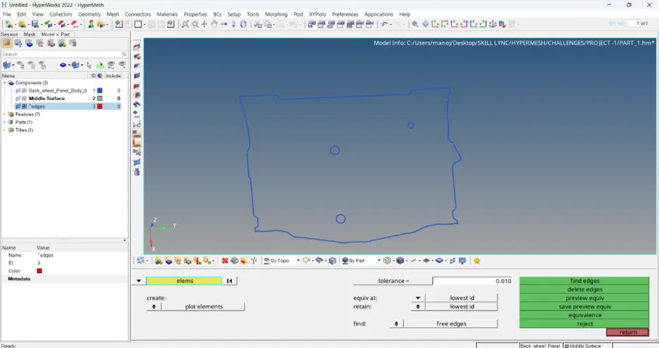
FIG 7 - CHECKING THE MESHED MODEL FOR FREEE EDGES.
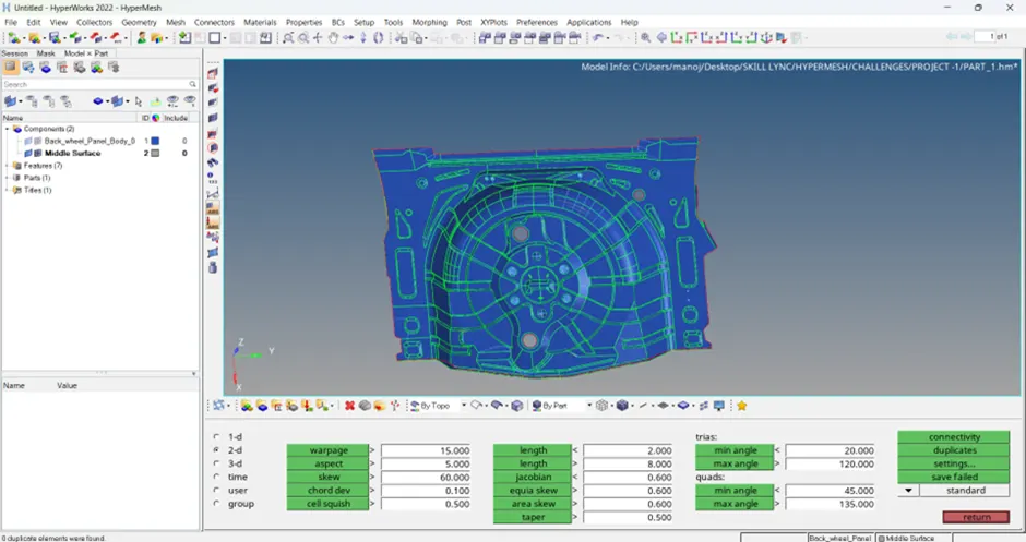
FIR G - 8 DUPLICATE CHECK
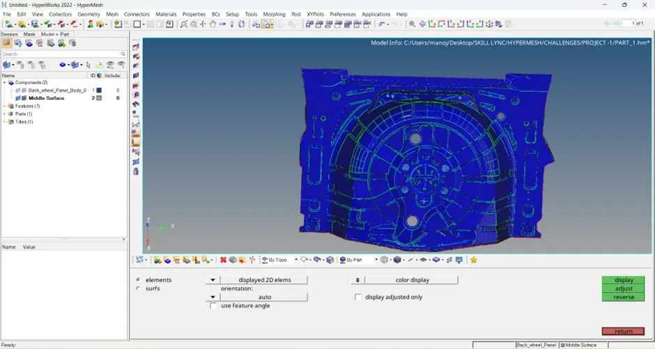
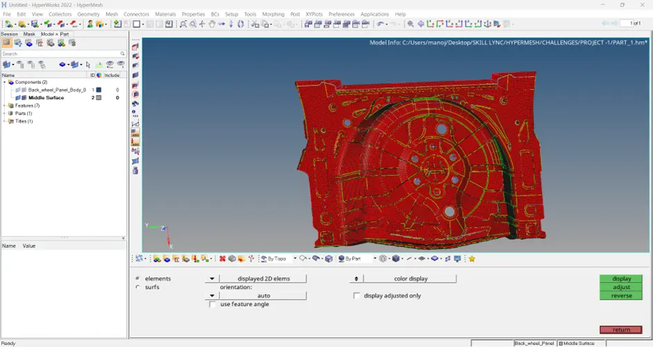
FIG - 9 CHECK FOR NORMALS.
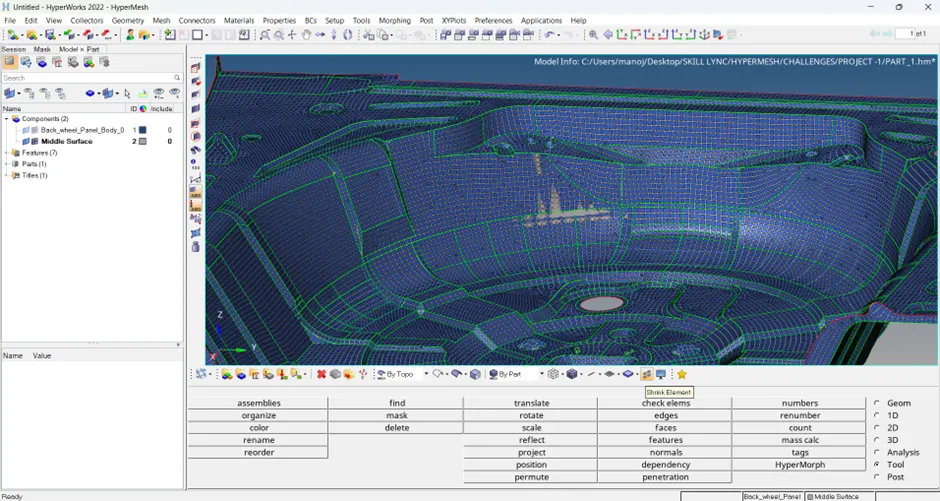
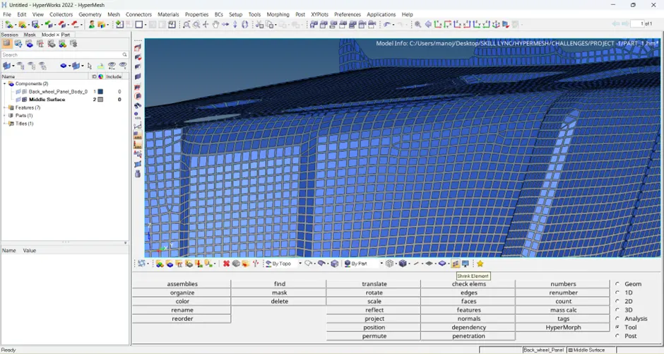
FIG 10 & 11 SHRINK ELEMENT REPRESENTATION.
Assigning Thickness to the Elements
- Begin by creating a property and material card in the browser.
- To create a property, right-click in the browser and select Create >> Property.
Once the property is
created, rename it appropriately and proceed to assign thickness to the
components
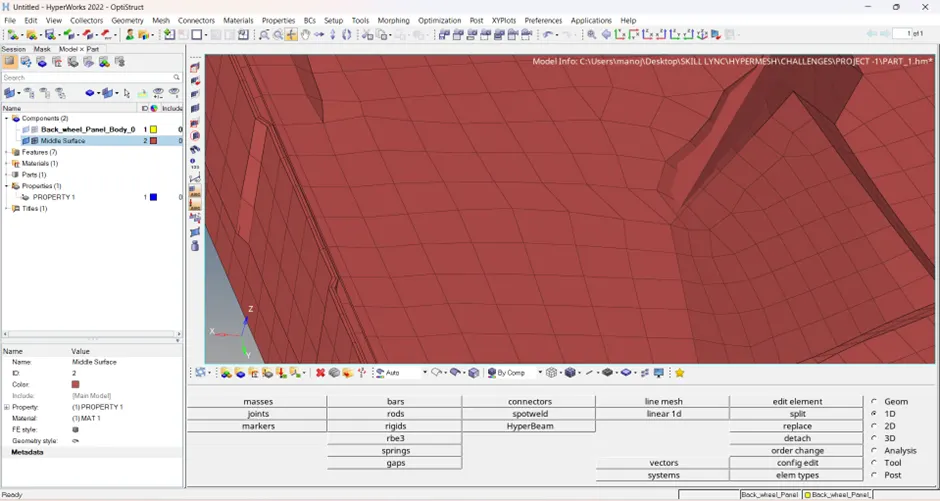
FIG - 12 AFTER ASSIGNING PROPERTY ANDAND THICKNESS TO THE MODEL.
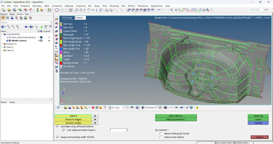
FIG - 13 FINAL MESH MODEL.
Results and Learning Outcomes
Results:
- Preprocessing Completion: Successfully completed the preprocessing of the Rear Wheel Holder (Spare Wheel Floor Panel) component using Hypermesh, ensuring that all necessary steps were followed for optimal modeling.
- Mid-Surface Extraction: Effectively extracted the mid-surface for both sheet metal and plastic components, utilizing the Auto Mid Surface Extraction feature. This streamlined the geometry, allowing for more accurate representation in the analysis phase.
- Meshing Accomplishment: Achieved a comprehensive meshing of the entire component with a specified element size of 5 mm and a mixed mesh type, which facilitated the creation of a well-structured mesh.
- Quality Checks: Conducted detailed checks for connectivity, free edges, duplicates, and normals, ensuring that the mesh was free of errors and optimized for simulation.
- Thickness Assignment: Assigned appropriate thickness values to the elements by creating and renaming property cards, which enhanced the accuracy of the simulation and reflected the physical characteristics of the materials used.
Learning Outcomes:
- Proficiency in Hypermesh Tools: Developed a solid understanding of how to navigate and utilize various Hypermesh tools for geometric cleanup and mid-surface extraction. This included manual techniques and the use of algorithms for complex geometries.
- Meshing Strategies: Gained insights into different meshing strategies, including the significance of element quality, alignment, and density. Learned how to adjust parameters effectively to achieve an optimal mesh flow.
- Error Identification and Resolution: Enhanced problem-solving skills by identifying common meshing issues such as free edges, duplicates, and misaligned normals. Gained experience in using specific tools to rectify these issues, improving the overall mesh integrity.
- Material Properties Understanding: Understood the critical role of assigning material properties and thicknesses to elements, which is essential for ensuring accurate and reliable simulation results in finite element analysis (FEA).
- Analytical Skills Development: Improved analytical skills by evaluating the impact of geometric and mesh configurations on simulation outcomes, preparing for more complex modeling challenges in future projects.
Overall, this experience not only solidified technical skills in preprocessing and meshing but also fostered a deeper appreciation for the nuances of accurate simulation modeling in engineering applications.
SINCE THE MODEL SIZE IS TOO BIG TO UPLOAD HERE THE MODEL AND THE REPORT CAN ALSO BE FOUND HERE
https://drive.google.com/file/d/1Hft7iapVy6CydaQikZic8NxoANextyDi/view?usp=sharing