Project 2 - 2D meshing on the instrumental Panel
Project 1 - 2D meshing on the instrumental Panel
AIM: Extract the mid-surface and create a 2D mesh for the instrument panel, adhering to specified quality standards.
OBJECTIVE:
- Conduct geometric refinement on the component.
- Generate a mid-surface from the original component.
- Mesh the component in alignment with prescribed quality parameters.
- Optimize meshing flow and rectify off-elements in fillet and rib areas where feasible.
- Establish distinct property IDs for the ribs, allocating appropriate thickness to each.
PROCEDURE: The process can be divided into three distinct phases:
PHASE – 1 - Importing and Setup
a) The CAD geometry will be provided to the FE modeler in various formats like .stp and .iges.
b) After importing and configuring the geometry within the ANSA tool, a TOPO operation was executed on the entire model to connect its diverse parts. Subsequently, within the mesh module, the model underwent refinement using the length command to enhance comprehension and clarity.
c) Following these procedures, a geometry assessment was carried out to evaluate the geometry's quality utilizing the checks manager module.
Accessed through TOOLS TAB >> CHECKS MANAGER >> GEOMETRY CHECK.
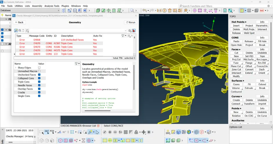
FIGURE – 1 - GEMOMETRY CHECK BEFORE FIXING TOPOLOGY ISSUES.
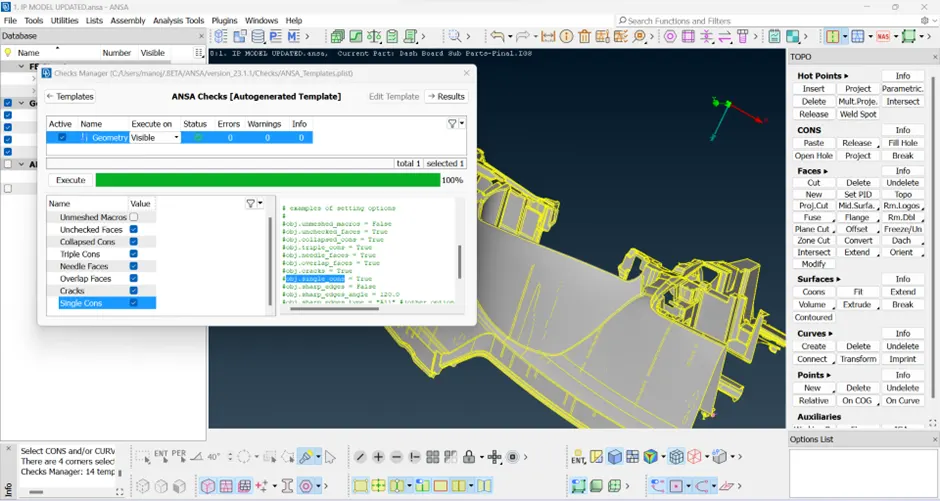
FIGURE – 2 - ALL THE GEOMETRIC ERRORS ARE RECTIFIED.
d) Many of the geometric and the topological issues such as unchecked faces, triple cons etc can be rectified in the checks manager itself. After addressing common issues such as needle faces and unchecked faces, a comprehensive assessment of the geometry ensured its quality. Upon achieving a favourable result, signified by a green signal in the geometry check, we were ready to initiate the mid-surface generation process.
PHASE - 2: Generating Mid Surface.
I partitioned the entire component into two sections to facilitate mid-surface and mesh generation. The initial component constituted one part, while the ribs formed the second segment.
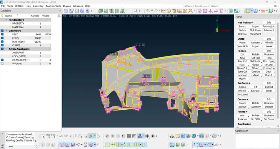
FIGURE – 3 – REAR SIDE OF IP PART SELECTED FOR MID
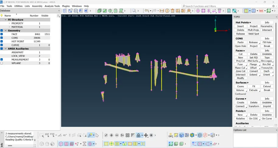
FIGURE – 4 – RIBS SEPERATED FOR EASY MID GENERATION.
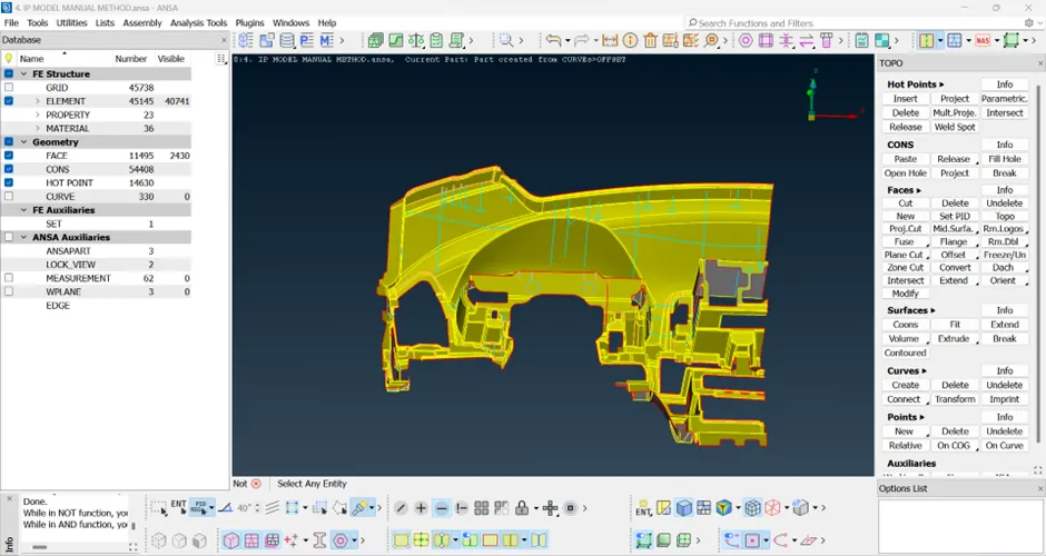
FIGURE – 5 – MID GENERATED FOR THE IP MODEL.
Here to generate mid, faces offset technique was used for the IP model, for ribs the mid was generated by creating curves around the circular cones.
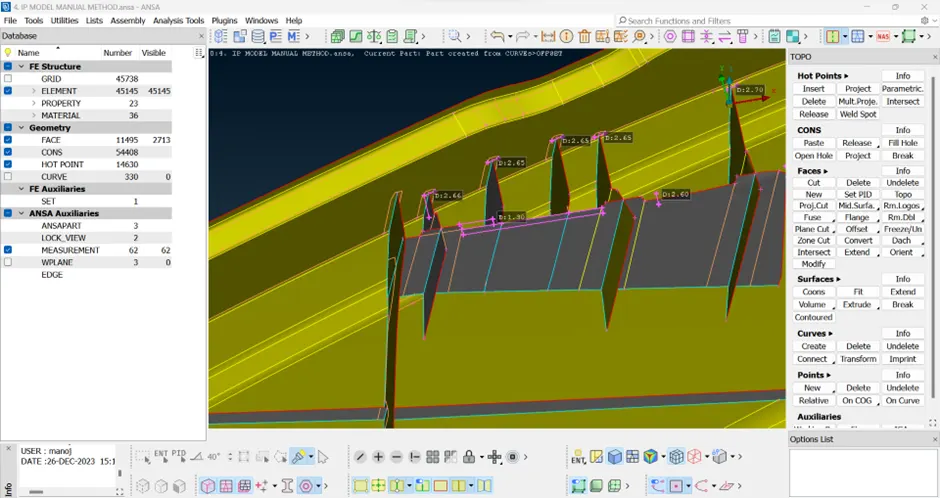
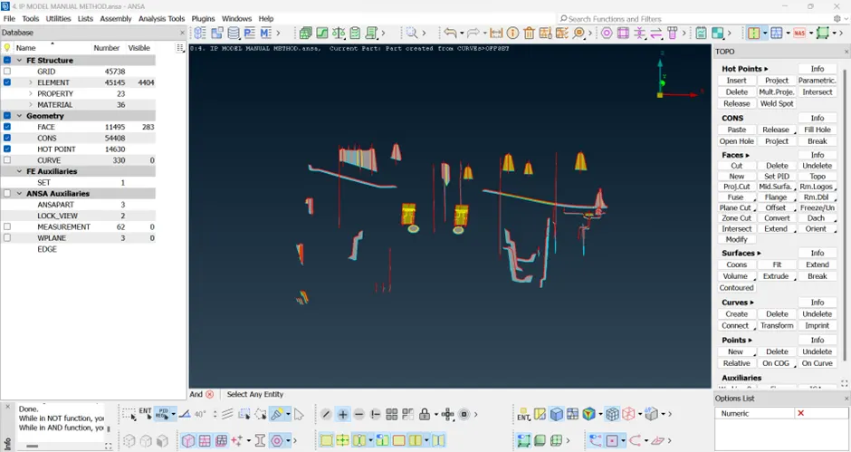
FIGURE – 5 – MID GENERATED FOR THE RIBS.
After generating the mid-surface, conduct another geometry check without selecting "Single cons" and “triple cons” as it's irrelevant for a mid-surface that doesn't create a closed volume.
Once the mid-surface is validated without issues, proceed with meshing the model.
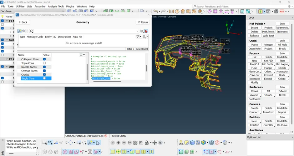
FIGURE – 6 – GEOMETRY CHECK PERFORMED ON MID SURFACE GENERATED.
PHASE - 3: Meshing.
a) Prior to progressing with meshing, it's crucial to define the mesh parameters. For this case, the target element length is configured at 4. Input the prescribed quality criteria, minimum element length, and maximum element length within the Mesh quality tab.
b) Adjust the Trias percentage and presentation parameters to elevate detail levels. Opt for the "Elements percentage" choice to further enhance the mesh refinement process.
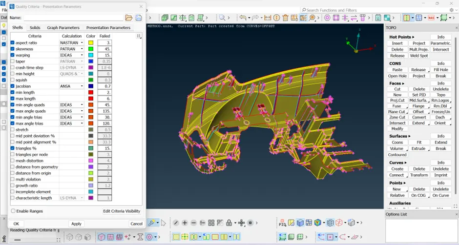
FIGURE – 7 – QUALITY PARAMETERS DEFINED FOR THE GEOMETRY.
c) Meshing begins via the MESH MODULE, utilizing the batch mesh algorithm to create a mesh for the entire model.
d) Irregularly meshed areas are erased, following which BEST MESH/SPOT MESH is applied to ensure a consistent mesh flow.
e) To elevate mesh quality and remove undesired triangular elements, various mesh refinement commands like RECONSTRUCT, IMPROVE, and SPLIT/SWAP/JOIN are utilized.
f) Material and thickness assignment to the model is accomplished using the SETPID command within the mesh module.
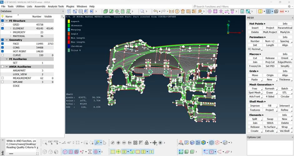
FIGURE – 8 – MESHED COMPLETED FOR THE MODEL.
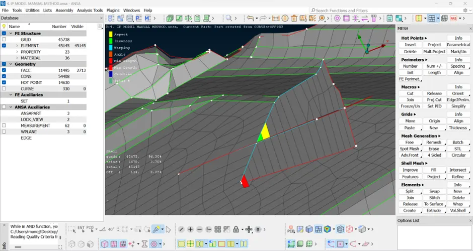
FIGURE – 9 – MESH ELEMENTS FAILED IN REGIONS.
Some areas contain elements that don't meet quality standards and can't be corrected. However, we can proceed with the meshing of the overall model.
Upon completing the body refinement, a total of 114 off elements were identified.
While generating the mid-surface, we linked the Property ID (PID) directly to the corresponding features, ensuring accurate thickness values aligned with the parent geometry. This method facilitated clear distinction and management of the features by transitioning between entity mode and PID mode in the viewing interface.
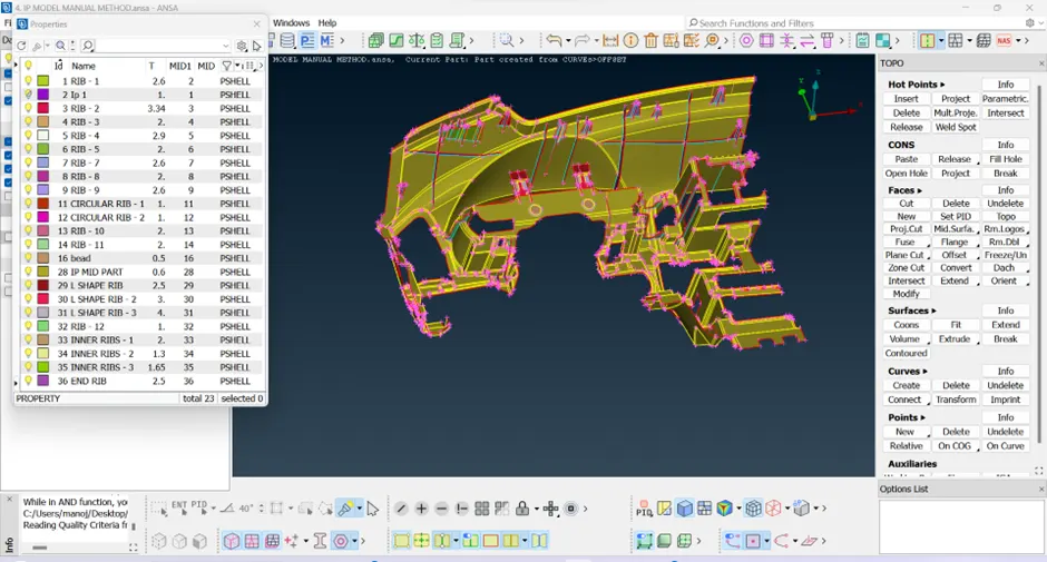
FIGURE – 10 – PID’s ASSIGNED TO THE MODEL.
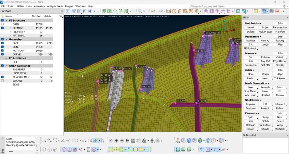
FIGURE – 11 – DRAW SHELLS AS SOLIDS MODE ON.
Conclusion
Throughout the meshing of the IP component, we dedicated ourselves to harnessing ANSA's pre-processing capabilities extensively. This focused effort aimed to refine CAD geometry, extract mid-surfaces, and create a mesh for the intricate component. Our strategy comprised systematically executed phases, each tailored to play a distinct role in achieving our ultimate objective.
Learning outcomes
- Acquired skills in cleaning intricate geometry.
- Mastered the utilization of align manager and casting technique at the onset.
- Gained proficiency in the versatile application of the batch mesh algorithm.
- Developed the ability to create an optimized mesh flow using a low tria percentage.
- Acquired expertise in extracting mid-surfaces for doghouses in a cross pattern.
- Learned the process of assigning thickness to components.
THE MODEL CAN ALSO BE FOUND IN THE BELOW LINK
https://drive.google.com/file/d/1mA2u47JNUKt_Wf-rjnXyq2R4Iyhod0na/view?usp=sharing