Week - 4 - 2D meshing for Plastic components
Week - 4 - 2D meshing for Plastic components
Aim: To generate a 2D surface mesh for the provided plastic component by extracting its mid-surface.
Objective: The primary goal is to develop a Finite Element (FE) model for a plastic component that complies with defined quality standards and exhibits a uniform mesh distribution.
Procedure: The procedure can be divided in several distinct phases, as follows:
1. Importing the CAD model and setting it up.
- The FE modeler will be provided with CAD geometry in various formats, such as .stp and .iges. In this instance, the initial supply of the model was in .igs format.
- After importing and setting up the geometry in the ANSA tool, a TOPO operation was executed on the complete model to link its different components. Following that, in the mesh module, the model was enhanced for better understanding and clarity through the utilization of the length command.
- Subsequent to these procedures, an evaluation of the geometry's quality was carried out using the checks manager module. Certain common errors, such as unverified surfaces and solitary constraints, were identified and effectively resolved.
- After rectifying common issues such as needle faces and unverified surfaces, a conclusive assessment of the geometry's quality was undertaken. Upon achieving a favourable result, denoted by a green indication in the geometry check, we could then advance to the mid-surface generation process.
- Upon achieving a favorable result, as signified by a green indicator in the geometry check, we were able to proceed with the mid-surface generation process.
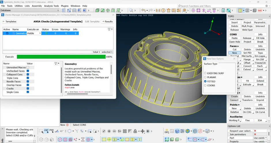
FIGURE 1 : Geometry check done and the geometry was rectified of errors.
2. Mid - Surface Extraction.
a). While extracting mid-surfaces for sheet metal components is usually straightforward with the "auto mid" command, the current task involves working with a plastic component, known for its varying thickness. Consequently, we need to resort to manual mid-surface commands for extraction.
b). Prior to commencing manual mid-surface generation, it is advisable to measure and record the thickness of each feature. This practice significantly facilitates our work.
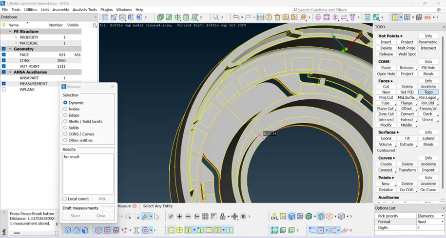
FIGURE 2 : Geometry Measured.
c). There are many ways to generate manual mid few are as follows:
1). Mid surface extraction using faces offset method. This method of mid-surface extraction is applied when the component's features have consistent and uniform thickness throughout.
In the "Faces Module," navigate to the "Offset Faces" option, select the relevant face, and specify the desired offset distance.
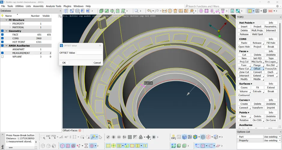
FIGURE 3: Offset method
2). In certain regions, I have employed a process to create curves between constraints and used those curves to generate a new surface that serves as the mid-surface for that specific area.
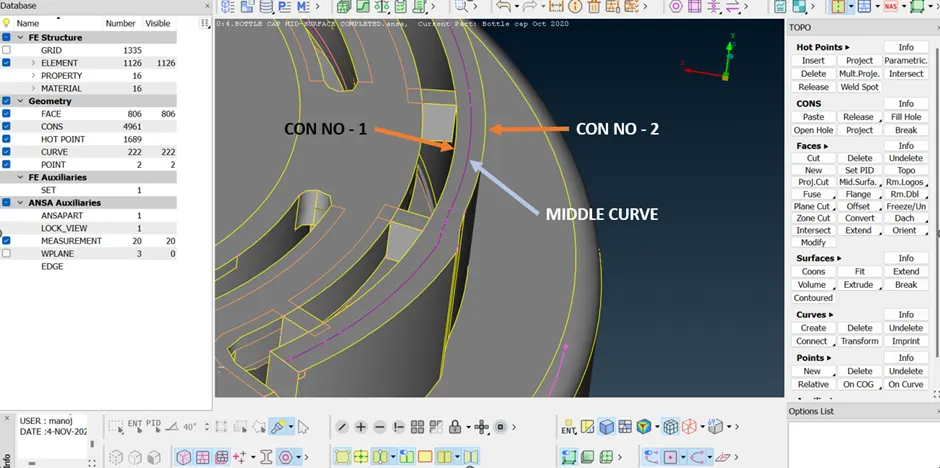
FIGURE 4 : Cons to curve method of Mid generation.
3). This technique was applied in other areas as well to generate the mid-surface.
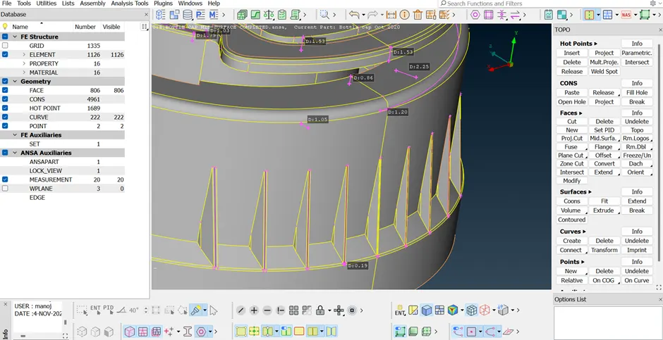
FIGURE 5 : Cons to curve method of Mid generation.
4). In specific regions, we also employed the "Middle Multi" option to extract the mid-surface.
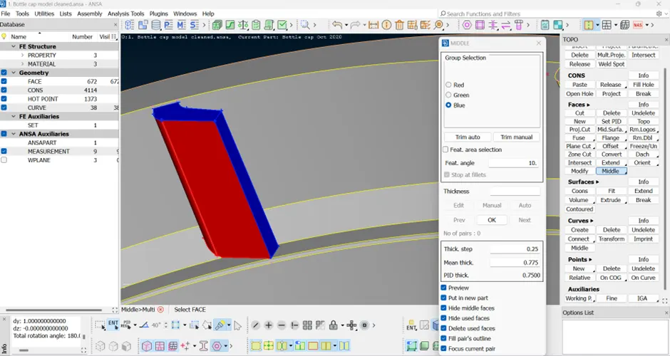
FIGURE 6 : Middle Multi command used to generate mid.
d). In areas with fin-like or tooth-like structures, we generated the mid-surface for one particular region and then duplicated it to other corresponding regions.
e). In cases where the model exhibited linear or symmetric characteristics, we could have employed the "Transform" option, specifically the "Copy" function followed by the "Translate" command.
f). In this context, we utilized the "Transform" option in the "Utilities Module," specifically choosing "Copy" and "Rotate." For an efficient mid-surface copy, we initiated the process by defining two center-of-gravity (COG) points, particularly significant due to the model's circular nature. These points served as references for copying the mid-surface.
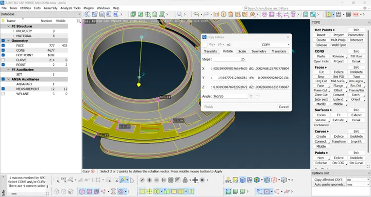
FIGURE 7 : Copying the mid using rotate command.
g). During the mid-surface generation process, we associated the Property ID (PID) directly with the respective features, concurrently specifying the correct thickness values as defined in the parent geometry. This approach allowed us to clearly distinguish and manage the features by transitioning from entity mode to PID mode in the viewing interface.
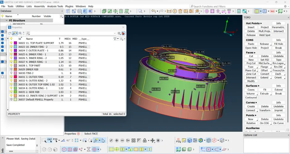
FIGURE 8 : Thickness assigned to the model.
h). Extending certain rib or tooth structures to the bottom surface can be achieved using the "Faces Module." Specifically, you can utilize the "Extend" command, then select the individual constraints, and specify the parent surface for the extension.
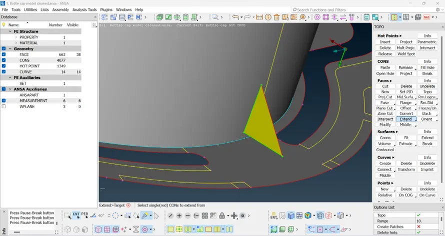
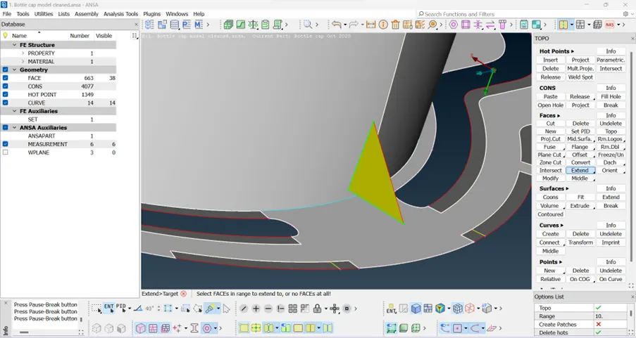
FIGURE 9 & 10 : Using Extend command.
i). After generating the mid-surface and conducting a subsequent geometry check, it's important to deactivate single constraints and triple constraints in the model, as these are typically present.
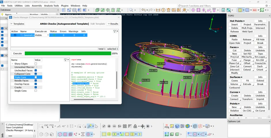
FIGURE 11 : Geometry check performed on the mid surface.
3. Meshing.
a).Following the last geometry check, we can advance to the meshing of the model. However, it's essential to establish appropriate quality criteria beforehand. In this particular instance, the target element length has been set at 1.
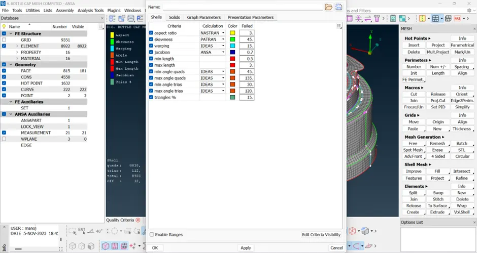
FIGURE 12 : Quality criteria defined.
b). The Trias percentage and presentation parameters are fine-tuned to improve the level of detail in the mesh. Furthermore, the "Elements percentage" option is selected to further optimize the meshing process.
c). The meshing process is initiated within the MESH MODULE, utilizing either the BEST MESH COMMAND or the SPOT MESH method.
d). To improve mesh quality and remove undesired triangular elements, we utilize various mesh refinement commands, such as RECONSTRUCT, IMPROVE, and SPLIT/SWAP/JOIN.
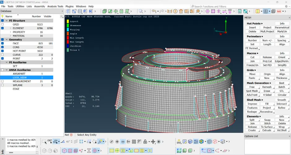
FIGURE 13 : Model Fully meshed.
e) In specific regions of the model, the presence of triple constraints is causing 12 elements to fail the quality criteria.
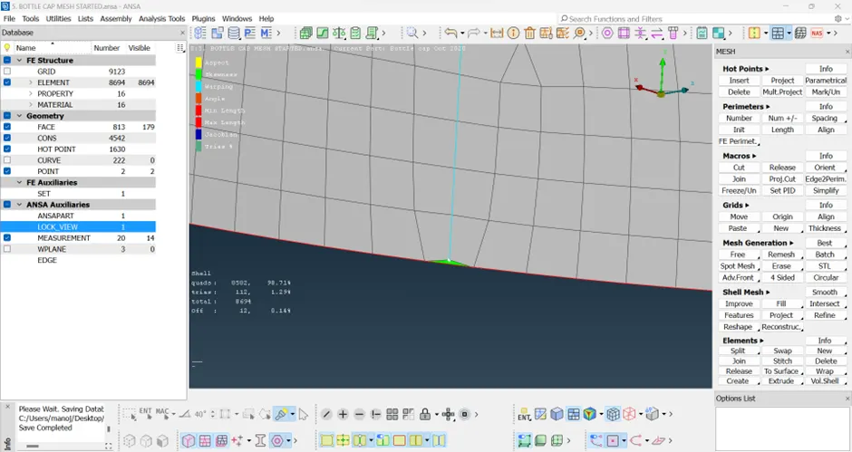
FIGURE 14: Region for elemental failure.
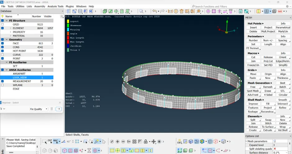
FIGURE 15: Region for elemental failure.
f). To verify the mid and mesh generated for the model we can switch on Draw shells as solids and can verify with the parent geometry.
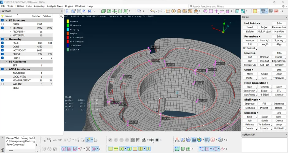
FIGURE 16 : Verifying the mesh generated.
Conclusion
During the process of meshing the plastic component, we undertook a comprehensive effort to leverage ANSA's pre-processing capabilities. This endeavor was centered on enhancing the CAD geometry, extracting mid-surfaces, and generating a mesh for the plastic component. Our approach involved a well-organized series of meticulously executed phases, each designed to fulfill a specific role in reaching our overarching goal.
THE MODEL CAN ALSO BE FOUND HERE
https://drive.google.com/drive/folders/18c1XVHpLr1AhW-BiDTPFuK8oi-F1Ec0Y?usp=drive_link