Week- 6 - Solid meshing
Solid meshing
Aim:
Mesh the provided rearview mirror component in both 2D and 3D, verifying the model for geometric errors and making necessary corrections. Additionally, ensure that the generated mesh adheres to specified quality criteria.
Procedure:
1). The first step is importing the model, a stage that frequently reveals various errors due to file formats. Rectification involves performing topological operations on the model, followed by refinement to decrease element lengths within the mesh module. This process is crucial to ensure the model's accuracy for analysis.
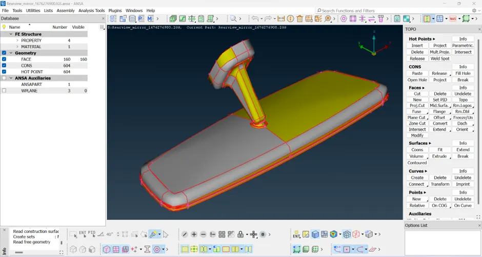
FIGURE – 1 MODEL BEFORE STITCHING / PERFORMING THE TOPOLOGICAL OPERATION.
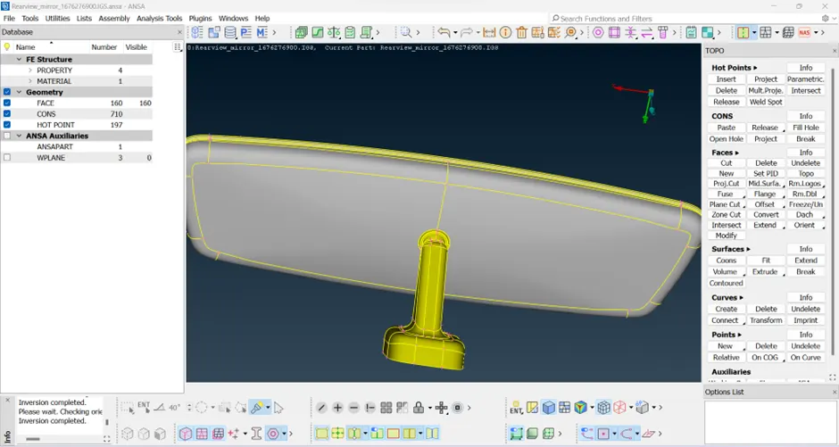
FIGURE – 2 AFTER STITCHING THE MODEL TOGETHER AND REFININNG THE LENGTH OF THE MODEL FOR BETTER REPRESENTATION.
2). After conducting a comprehensive analysis of the model, the subsequent step involves verification through the Geometry Checks Manager. This step ensures the identification and resolution of potential geometric errors that might hinder the meshing process. You can access this by navigating to Checks Manager >> Geometry Check.
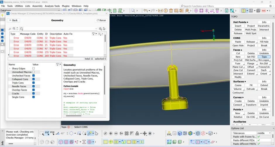
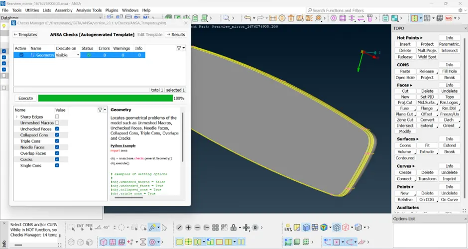
FIGURE – 3 & 4 GEOMETRY CHECK BEFORE AND AFTER RECTIFING THE GEOMETRICAL ERRORS.
3). After the geometrical errors were rectified, we can with meshing the model by setting the necessary 2D and 3D quality criteria.
Please note the following guidelines:
For 2D elements, focus on assessing minimum and maximum length errors.
For 3D elements, concentrate on identifying Tet Collapse errors.
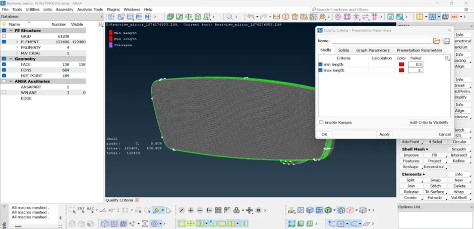
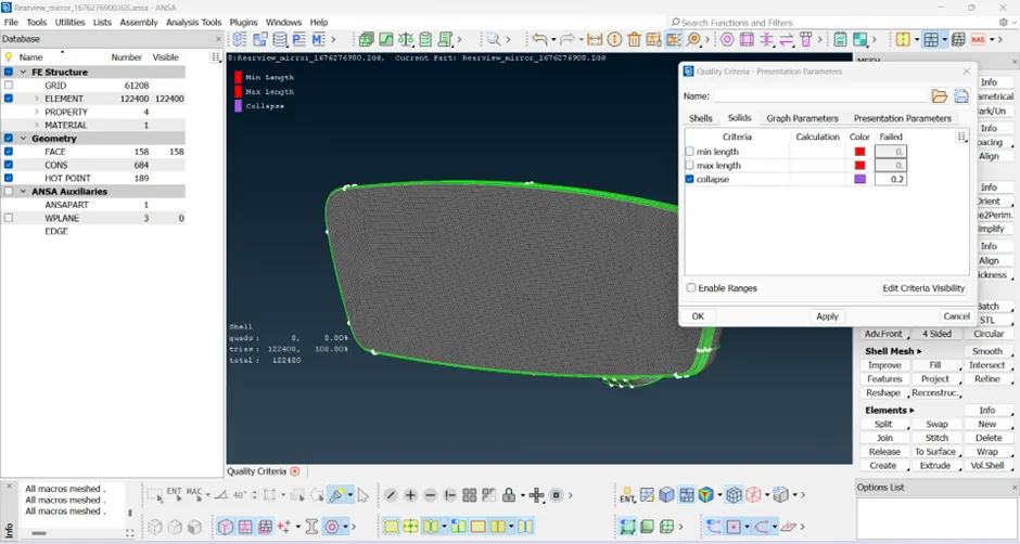
FIGURE – 5 & 6 QUALITY PARAMETERS DEFINED FOR THE 2D AND 3D ELMENTS.
4). Once the quality parameters are established, the next step involves surface meshing of the component. Utilize ortho-tria elements for curved faces, feature regions, etc., as they prevent distortion of the geometry surface. For faces with flat surfaces, normal tria elements can be employed for 2D meshing.
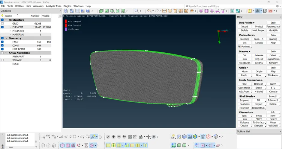
FIGURE – 7 FULLY SURFACE MESHED MODEL.
5) Following surface meshing, the next step involves defining the volume of the model to proceed with 3D meshing. You can achieve this by accessing the VOLUME MODULE >> DEFINE >> SELECT THE MODEL TO DEFINE THE VOLUME.
6) Once the volume is defined, within the same volume module, navigate to the unstructured mesh tab. Here, you can choose between the Terta rapid or Terta FEM algorithms to generate the unstructured mesh for the volume.
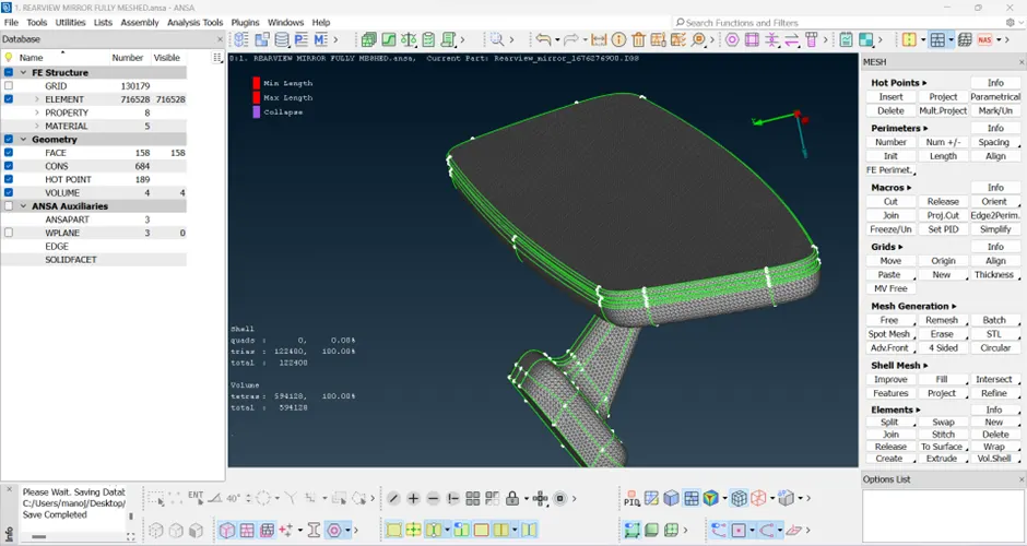
FIGURE – 8 FINAL MESH GENERATED AFTER COMLETEING BOTH SURFACE MESH AND 3D MESH.
7). The volume mesh generated can be assigned individual PID's (Property IDs).
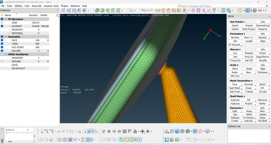
FIGURE – 9 3D MESH IN PID MODE.
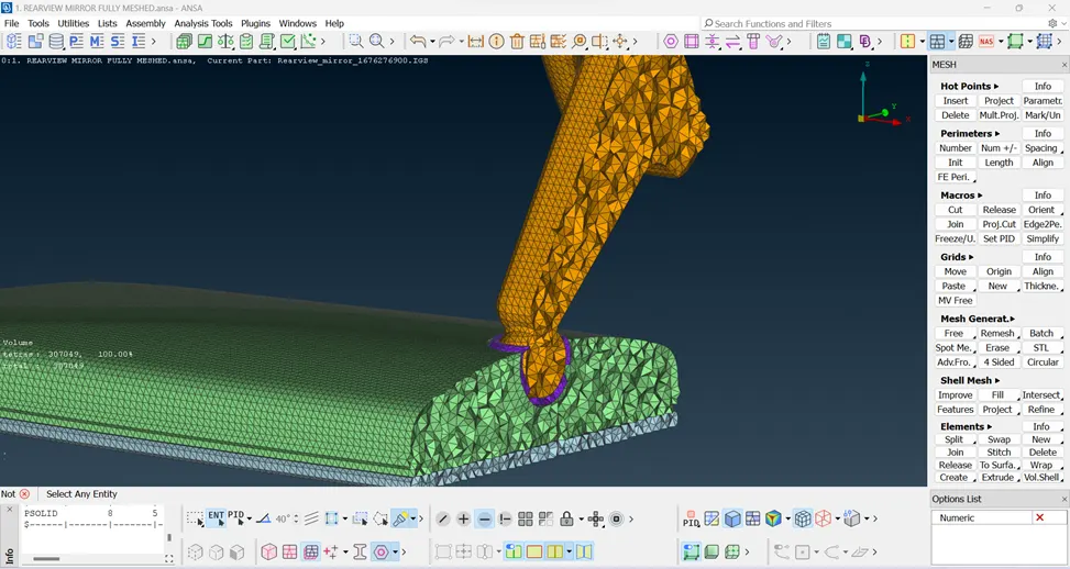
FIGURE – 10 3D MESH IN A CROSECTIONAL VIEW.
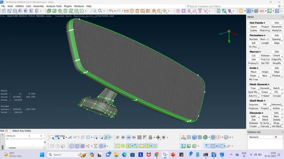
FIGURE – 11 FINAL IMAGE OF THE MODEL.
Conclusion.
The component was geometrically corrected and meshed according to specified requirements and criteria. The resulting shell mesh served as the basis for creating a solid mesh. Quality and flow were meticulously maintained, ensuring no surface deformations occurred.
Learning outcomes.
1). Acquired knowledge about tools pertaining to solid meshing.
2). Gained expertise in assigning volumes to enclosed shell element regions.
3). Learned how to address tet collapse failures.
4). Explored the concept of unstructured mesh.
MODEL CAN ALSO BE FOUND USING THE BELOW LINK
https://drive.google.com/drive/folders/1Gq02Qo64DRPcYdmnMdGfFSsu2T1KIq8O?usp=sharing