Project 1 - Meshing of Floor Panel
Project 1 - Meshing of Floor Panel
Aim: The primary goal is to develop a Finite Element (FE) model that adheres to specified quality parameters and exhibits a smooth mesh distribution for a floor panel component.
Objective: The main objective is to create a Finite Element (FE) model for a floor panel component that meets specific quality standards and displays a seamless mesh distribution.
Procedure:
The process can be divided into three distinct phases:
1). Phase 1: Importing and Setup :
a). The FE modeler will receive the CAD geometry in different formats, including .stp and .iges. In this case, the model was initially supplied in .igs format.
b). Once the geometry was imported and configured within the ANSA tool, a TOPO operation was performed on the entire model to connect its various parts. Subsequently, in the mesh module, the model was refined for improved comprehension and clarity using the length command.
c). Following these steps, a geometry check was conducted to assess the quality of the geometry using the checks manager module. TOOLS TAB >> CHECKS MANAGER >> GEOMETERY CHECK.
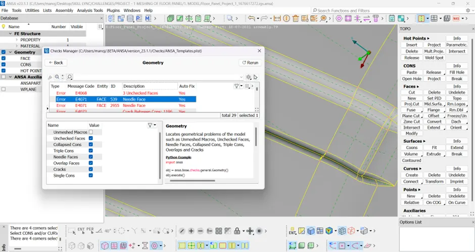 FIGURE 1 : Geometry check done and many geometric errors were Identified.
d). Some common errors, like unchecked faces and visible single cons, were addressed and resolved.
e). A second geometry check was performed to verify the absence of triple cons, and in certain instances, ANSA was capable of automatically resolving the majority of these issues. However, in some cases, triple cons had to be manually addressed. Additionally, many of the needle faces required manual correction, involving the deletion of existing faces and the creation of new ones.
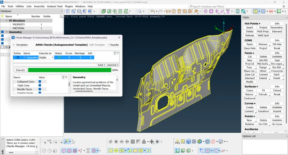 FIGURE 2 : Geometry check done and the geometry was rectified of errors.
f). Once typical problems like needle faces and unchecked faces had been corrected, a final evaluation of the geometry was conducted to confirm its quality. When a positive outcome was attained, indicated by a green signal in the geometry check, we could proceed to the mid-surface generation process.
2). Phase 2: Generating Mid Surface.
a). After cleaning the model, it is necessary to measure the model's thickness, as this information will be beneficial for generating the mid-surface in the later phases of the Finite Element (FE) modeling process.
b). After this rerun the check manager >> Geometry. To verify once again if the existing model is free from all the errors. If the geometry is fixed and if there are no errors ANSA will give a green signal once the command is finished.
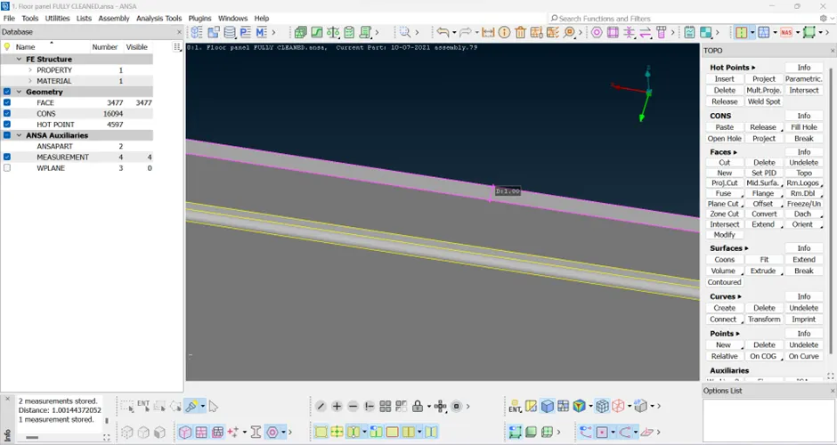 FIGURE 3 : Geometry thickness measured.
c). The “auto-mid” command is initiated by following these steps: navigate to the TOPO MODULE, then the FACES MODULE, and select the MID.SURFACE OPTION, specifically choosing the SKIN function. You will need to select the appropriate red, green, and blue faces.
Here’s an important note for your reference: Select the Appropriate Red, Green, and Blue Faces:
a. The Red color represents the top surface of the model.
b. The Green color represents the bottom surface.
c. The Blue color represents the model’s thickness.
d). Make sure to select these faces correctly for a successful mid-surface generation.
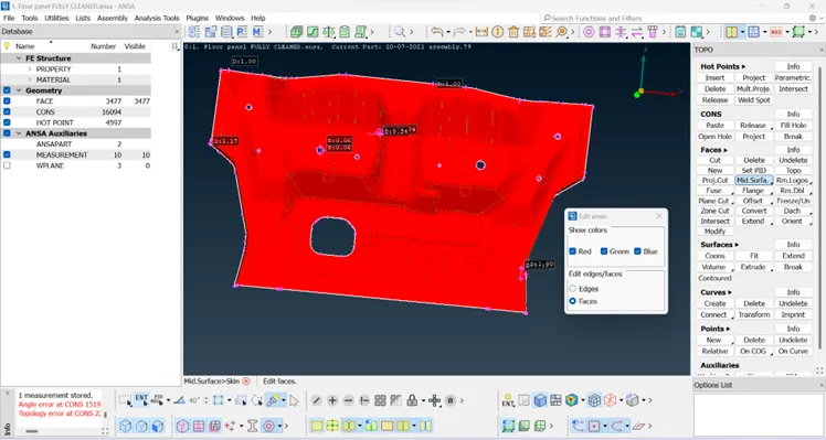
FIGURE 4 : Top Surface selected for Auto mid.
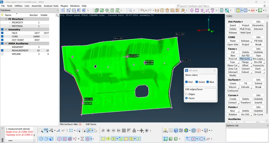
FIGURE 5 : Bottom Surface selected for Auto mid.
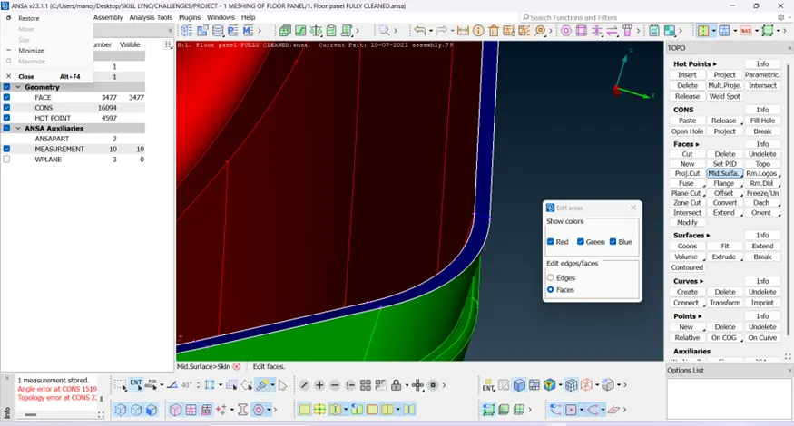
FIGURE 6 : Side Surface selected for Auto mid.
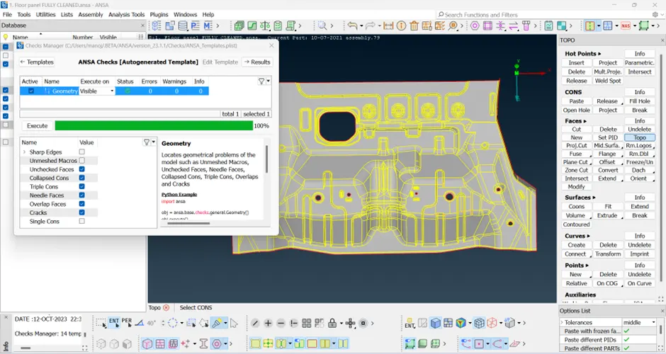 FIGURE 7 : Mid Surface generated and Geometry check once again Performed.
e). Once the mid-surface is generated, another geometry check needs to be performed. However, this time, ensure that "Single cons" is not selected in the check because it is not relevant for a mid-surface, which does not form a closed volume.
f). After confirming that there are no issues with the mid-surface, you can proceed with the meshing of the model.
3). Phase 3: Meshing.
a). Before advancing with the meshing process, it’s essential to establish the mesh parameters. In this particular instance, the target element length is set to 5. In the Mesh quality tab, input the specified quality criteria, minimum element length, and maximum element length.
b). The Trias percentage and presentation parameters are adjusted to enhance the level of detail. Additionally, the "Elements percentage" option is chosen to further refine the meshing process.
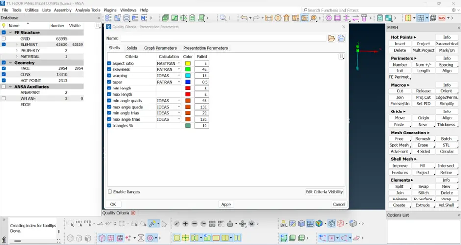 FIGURE 8 : Quality Parameters are defined for the geometry.
c). Areas in the model where the mesh element size could potentially encounter issues are recognized, and a process known as “defeaturing” is executed to address these concerns.
d). Efficiently capturing all the bead features in the geometry can be achieved by creating a cut precisely at the center of each bead. This method ensures a smooth and proper mesh flow over these features. Similarly, the entire model should undergo defeaturing to enhance the overall mesh flow of the model.
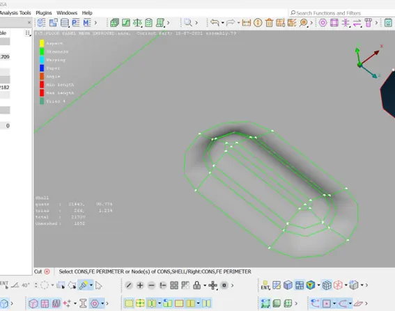
FIGURE 9 : Centre cuts inserted over beads in the geometry.
e). The meshing process is initiated by using the MESH MODULE, and the BEST MESH COMMAND or SPOT MESH is employed. In certain regions of the geometry, BATCH MESH is also utilized to achieve the desired meshing.
f). To enhance the mesh quality and eliminate unwanted triangular elements, several mesh refinement commands, including RECONSTRUCT, IMPROVE, and SPLIT/SWAP/JOIN, are employed.
j). Material and thickness can be assigned to the model by utilizing the SETPID command within the mesh module.
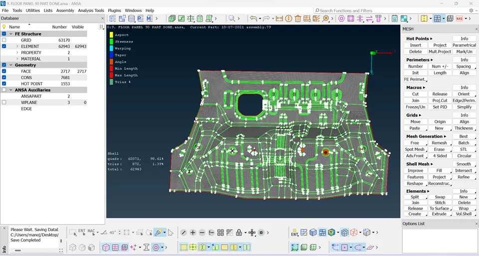
FIGURE 10 : Model completely Meshed.
Conclusion
Throughout the "Meshing of floor panel challenge," we embarked on an extensive effort to utilize the pre-processing capabilities of ANSA. This journey focused on improving CAD geometry, extracting mid-surfaces, and creating a mesh for an automobile floor component. This task was organized into a series of meticulously executed phases, each serving a specific purpose in achieving the overarching objective.
PLEASE FIND THE MODEL HERE -
https://drive.google.com/drive/folders/1539qUUQXnuHPufNnR62a0IwHz_26nroT?usp=drive_link