Project 1-Meshing of Rear Wheel Holder challenge
PROJECT: Meshing a "Rear Wheel Holder" with the given quality criteria.
Target element length = 5 units.
| S.N | Quality Criteria | Value |
| 1 | Aspect Ratio | 5 |
| 2 | Skewness | 45 |
| 3 | Warping | 15 |
| 4 | Taper | 0.5 |
| 5 | Min. Length | 2 Units |
| 6 | Max. Length | 8 Units |
| 7 | Min angle Quad | 45 |
| 8 | Max angle Quad | 135 |
| 9 | Min angle Tria | 20 |
| 10 | Max angle Tria | 120 |
| 11 | Tria % | 10 |
PROCEDURE: The following steps are to be performed to mesh the component while fulfilling the given quality criteria.
1. Importing the Geometry & organizing the components.
2. Geometry cleanup
3. Mid surface extraction and cleanup
4. Assigning the quality criteria
5. Meshing and assigning thickness
6. Checking for the duplicate elements, free edges in between elements and element orientation
Each step will be discussed in depth in the subsequent sections.
1. Importing the Geometry: The first step involves importing of CAD geometry into the hypermesh tool. The format of the imported geometry file is: ".iges". Once the geometry is imported, a through visual check is done on the part geometry to check for any missing surface or irregularities. This is done in preparation for the extraction of the mid-surface and to make sure that the anomalies of the imported geometry are not passed to the extracted mid surface.
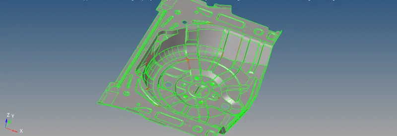
Fig.1
It can be seen in the fig.1 that the imported geometry has several errors such as missing surfaces, deformed surfaces.
2. Geometry cleanup: The Geometry cleanup is done so that a good mid-surface can be extracted from the geometry. At many places it was found that surfaces were missing and at the edges the surfaces were not connected properly (Fig.2-5). This was solved by deleting the bad surfaces and making new surfaces and stitching them properly with the adjacent surfaces. This can be seen in the (fig.4-6).
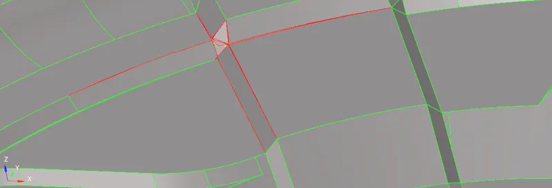
Fig.2
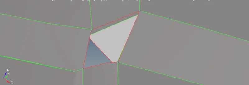
Fig.3
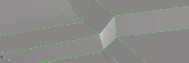
Fig.4
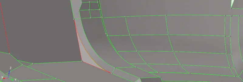
Fig.5
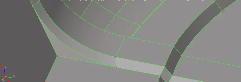
Fig.6
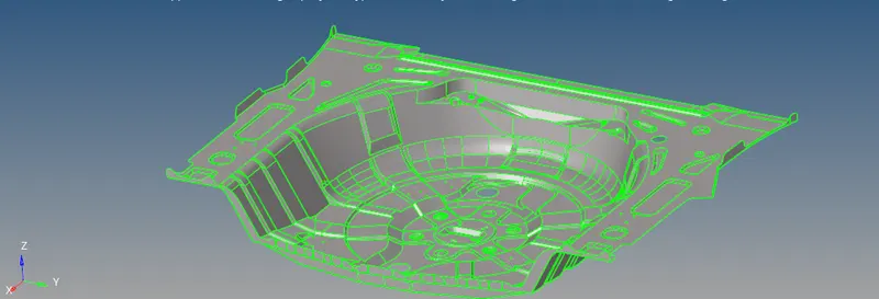
Fig.7
The imported geometry was corrected and was properly made ready for the mid-surf extraction. (fig.7)
3. Mid surface extraction and clean-up: Since our components are sheet metal components with constant thickness (0.75 mm), therefore the optimal way to mesh the components is by extracting the mid surface, meshing it and then assigning the thickness to the mid surface mesh.
The mid surface is extracted using the auto midsurface (geometry > auto midsurface > offset + planes + sweeps) (fig.8).
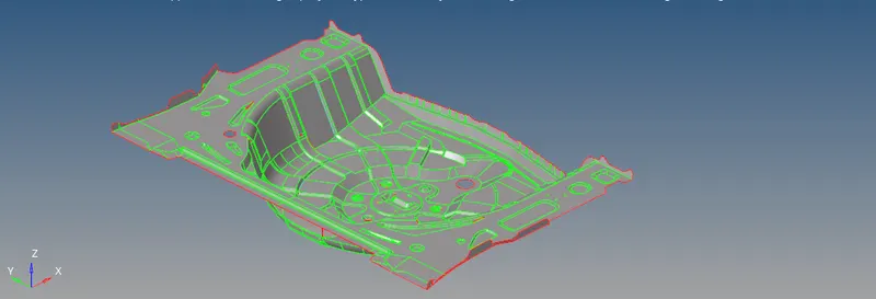
Fig.8
As the parent geometry is quite complex, the extraced mid-surface is not perfect and many irregularities, missing surfaces, unstitched edges can be found. Using various tools in the geometry panel the missing surfaces are filled using surface edit while some complex surface which are missing are offset manually from the parent geometry using offset (Geometry > surface edit > offset). This can be visualized in the below figs.9-10. Also, the necessary double cons (shared edges) are suppressed inorder to get a better mesh flow in that region.
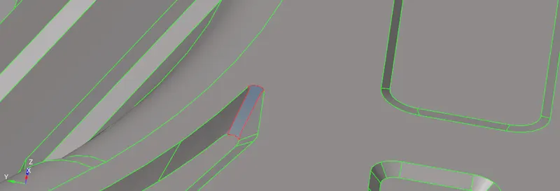
Fig.9
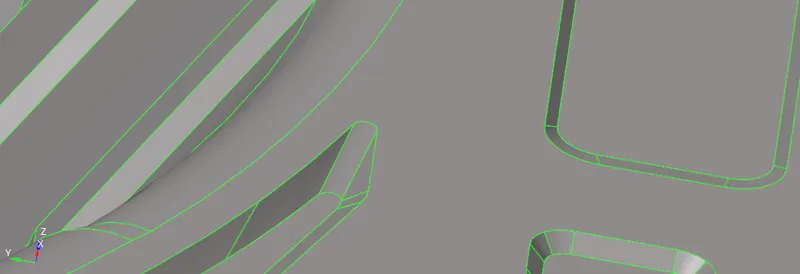
Fig.10
4. Assigning the quality criteria: After the mid-surface is cleaned, it now prepared for meshing and the given quality criteria is assigned (preferences > criteria file settings) (fig. 11).
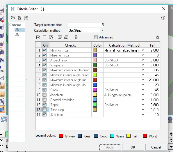
Fig.11
5. Meshing and assigning thickness: The mid surface is meshed using automesh with target element size = 5 and mixed type mesh (trias + quads). The surface is meshed in patches, starting from the complex regions and and the failed elements are corrected using various options like, split, combine, rebuild mesh etc. (fig.12). After a certain region is meshed the trias are minimized and shifted away from edges. it can be seen in the fig.12 that after correcting the elements the no. of failed elements has been brought down to zero. Also, the number of tria elements are minimized. A new property defining the thickness (0.75 mm) of the mesh is defined and assigned to the mid-surface of the geometry.
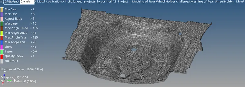
Fig.12
6. Checking for the duplicate elements, free edges in between elements and element orientation: The duplicate elements are checked and free edges in bewteen elements are checked using (tool > edges > find edges > preveiw equivalence > equivalence) (Fig.13).
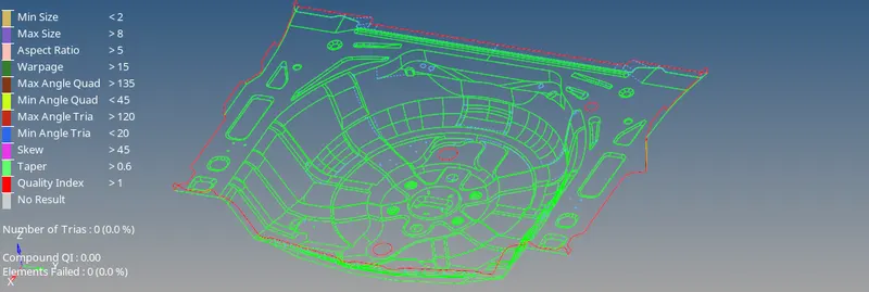
Fig.13
Also the element orientation is checked using (tool > normals) to make sure that the elements on the same face have same sense of orientation (fig.14).
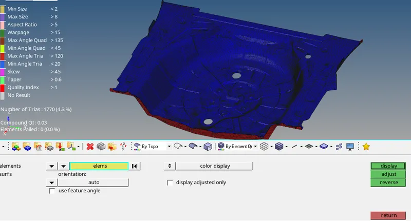
Fig.14
The final meshed elements with 0.75 mm thickness capturing the entire geometry can be seen in the fig.15 below:
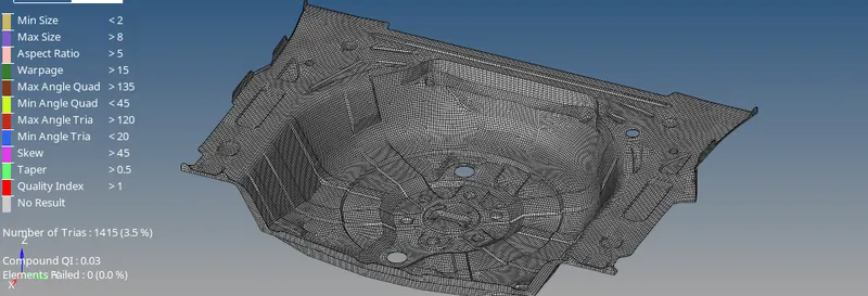
Fig.15
NOTE: Find the hypermesh file in the attachments.