Project 1-Meshing of Rear Wheel Holder challenge
Aim: To mesh the supplied component and extract a mid surface.
Given model:
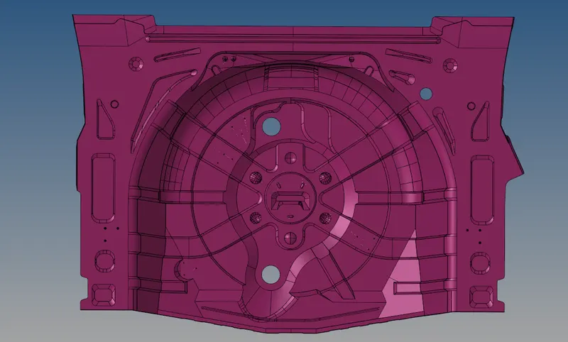
Objectives:
- To check the model for geometrical errors.
- To remove a component's mid-surface.
- Defeature and clean the Midsurface to remove any features and prevent any minimum length issues.
- meshing.
- To mesh the midsurface while attempting to reduce the quantity and concentration of trias.
- Remove any components that violate any established Quality standards.
- To give the mesh a thickness based on the component.
- Verifying for uncut edges.
Procedure:
1. The first step in starting the meshing process on the model is to geometrically clean it when we import it. During the importing process, there may be some errors. The procedure of defeaturing all the fillets that will fail for the minimum length requirement when we mesh on it is an additional step during the geometric clean up. So we can either remove these types of fillets in the parent surface or separately in the mid-surface.
We can increase the mesh flow overall by making the extraction of the mid surface more easier. After we have completed the Defeature command, we must switch to the surface view to "By Topo" to look for any free edges and, if necessary, resolve them.
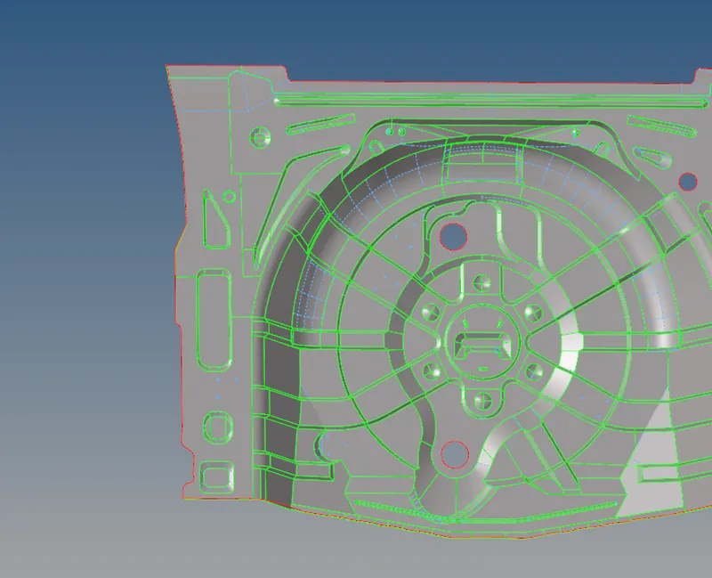
2. When we have cleaned up the geometry, we will extract the component's mid surface. Because the component has a more or less uniform thickness, we can use the Midsurface command from the Geometry tab. To achieve a much better mid-surface, alter the extraction option in the midsurface command to "Skin offset."
After extracting the mid-surface, we must proceed to clean the mid-surface for any areas where we may encounter a minimum length mistake. To accomplish so, we must first measure the distance between two spots on the surface where we may find an element that fails the minimal length test. To calculate the distance, we must utilise the Distance command from the Geometry tab (shortcut-F4).
NOTE:- Shortcuts are key to reduce meshing time, so we are trying to recall and use shortcuts keys along with function
Then we choose two points and measure the distance between them. If the distance is less than the minimum element length, we either toggle the line or take a mid-line of the feature to capture it as well.
To get the midpoint, use the Lines command on the Geometry tab. The mid-line option is available in the lines command. After selecting this option, we choose the two lines from which we need to extract the mid-line.
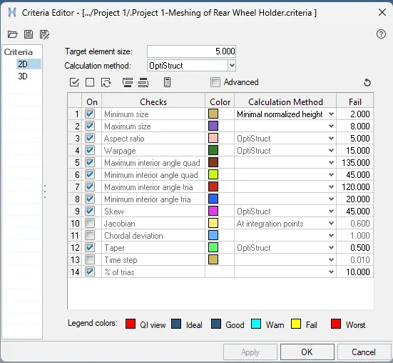
3. Before to strat meshing, we must define the Quality criterion for the meshing procedure. To accomplish this, navigate to the Preferences tab and select the Criteria File Configuration option. In this option, we must enter all of the required Quality criteria values, such as the minimum and maximum lengths, as well as the value for warpage, and so on.
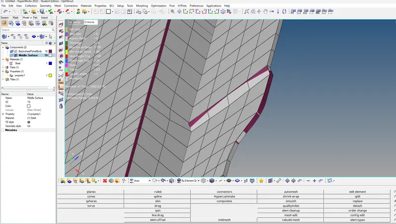
4. Once the Quality requirements have been established, we must proceed to mesh the midusrface. To mesh the component, we must use the Automesh command (Shortcut-F12) from the 2D Tab. Change the element type to "Mixed" and the average element length to 5mm in this command (as given in the Quality criteria).
Keep the flow Align and size option checked at all times since it will result in a much better mesh flow on the component. The standard meshing criteria must be maintained here, such as not having a tria element on a feature line and avoiding rotating Quad elements in the mesh. We must also keep the tria count as low as possible because tria elements are significantly stiffer than quad elements, yet tria elements must take precedence over the existence of Rotational Quad Elements. We just need to remesh these regions if we obtain any Fixed/Pattern Tria.
Alternatively, we can simply divide the Rotational Quad elements into two distinct tria elements pointing in opposite directions, or we can divide the Fixed/pattern tria elements into three distinct tria elements pointing in opposite directions.
5. Once the Meshing is complete, the next step is to look for parts that failed the prior Quality criterion. To confirm this, we need to look in two locations. The first is in the 2D tab, under the Quality check command. Here we may view all of the items that violate any Quality criterion, such as minimum length or aspect ratio.
6. Now that the model has passed all of the Quality requirements, the following step is to give it a thickness. When assigning thickness, the initial step is to measure the thickness at various points across the model.
To give suitable thickness to the elements, we must first establish properties and alter the thickness value for each attribute. To create a property, right-click on the tree again and pick the Create option, then select the Property option.
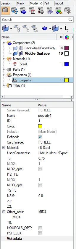
After we create the property, we must change the thickness value for this property. The thickness value for a property is found beneath the value of "T" in the property tab.
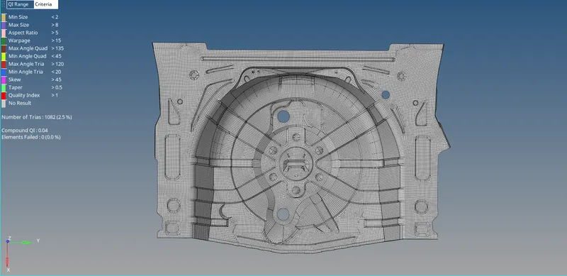
Conclusion: I'd like to note that this project helped me acquire a better understanding of all the meshing procedures and how to address a specific problem, as well as Quality clearing and Geometry Clean up.