Project 1-Meshing of Rear Wheel Holder challenge
Project 1-Meshing of Rear Wheel Holder challenge
Aim: To perform preprocessing on the given Rear Wheel Holder Sheet Metal component using hyper mesh preprocessing software
Objective:
- Generating the mid-surface and geometry cleanup on the given component.
- Generating mesh on the given component with low trias concentration and proper mesh flow.
- The given model should pass all the given quality parameters.
Procedure:
- Import the geometry from the saved location.
- File > Import > Import Model > File type > Open File > Import File.
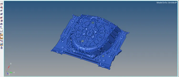
- Switch to Topo mode, and examine whether any solid component exists or not. If a solid component exists, we can delete the solids as we perform 2D meshing of the component.
- Delete [F2] >> Solids >> Select by box selection >> Delete Entity.
- Before working on the model, we have to check its geometry for any possible errors that can hinder the midsurfacing such as damaged geometry, unnecessary free edges, and connectivity errors.
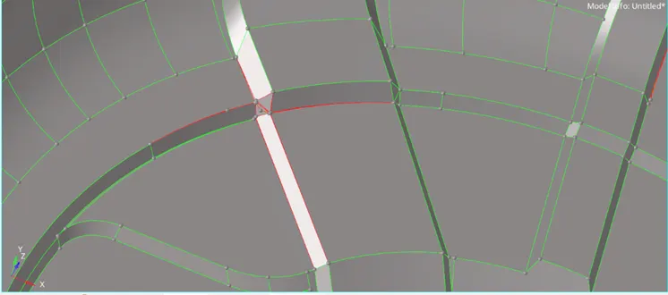
- After correcting these errors, some organizing can be done. It can be seen that on importing, there are 17 components altogether. This can be organized into a single component using the organized tool.
- Tool >> Organize >> Collector Subpanel >> Switch to Surfaces >> Select by Collector >> Move.
- Next is to check the thickness of the model. As the given model is sheet metal, we get a uniform thickness of 0.75mm.
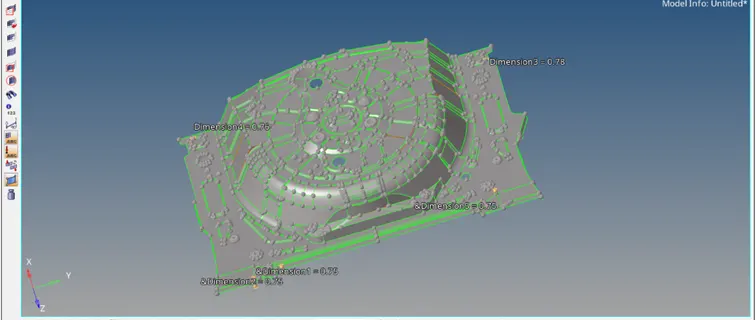
- Normally a check for symmetry can also be performed but in this case, very minimal symmetry can be seen. Hence the model can be worked on normally as a whole.
- Before extracting the mid-surface certain deformed surfaces, and overlapping surfaces can be corrected.
- The next step is to extract the mid-surface. Set offset extraction and select the surface to be extracted.
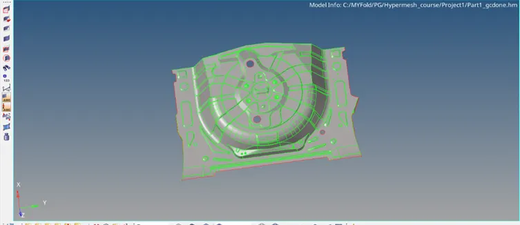
- After extracting the mid-surface, geometry cleanup can be done on the mid-surface extract.
- Try to eliminate free edges, and irregular surfaces, and fix overlapping surfaces.
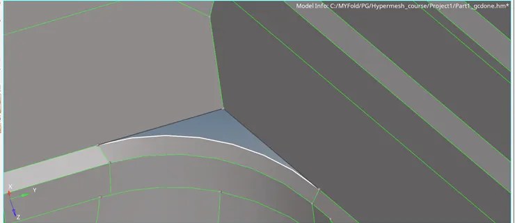
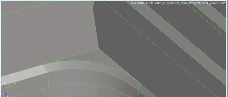
- After this, we can proceed with the meshing of the mid-surface. This can be done through the auto mesh panel. Set the criteria in the criteria file and also set the target element size as 5.
- Go to Element Cleanup and perform a cleanup to remove elemental errors from the mesh.
- Use the rebuild mesh option to reorganize the mesh pattern to obtain a smooth mesh with a lesser number of trias.
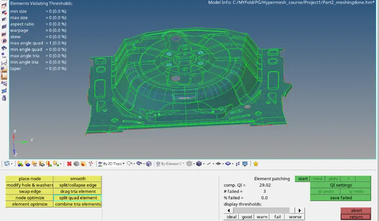
- Reduce the errors in elements that fail for quality.
- Finally, check for normal.
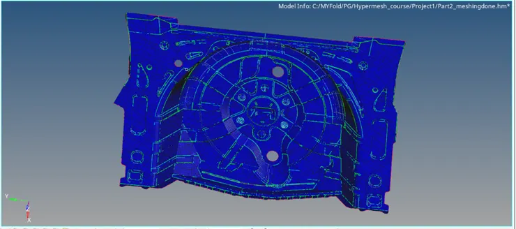
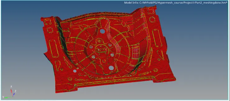
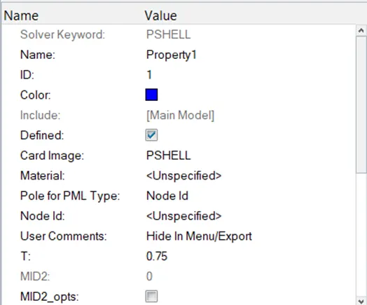
- Next is to assign thickness to the mid surface. Right-click on the component tree and create a property. Add the Property tab: add PSHELL as a Card image and set thickness as 0.75 next to the ‘T’ column.
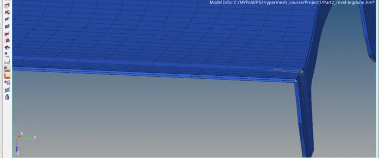
- Assign this property to the component. Now that the property is assigned, we can view the 3D elements with the thickness assigned by changing the view from "2D Traditional Element Representation" to "2D Traditional and Element Representation". The final Thickened mesh will look something like the following.
- Final CAD image:
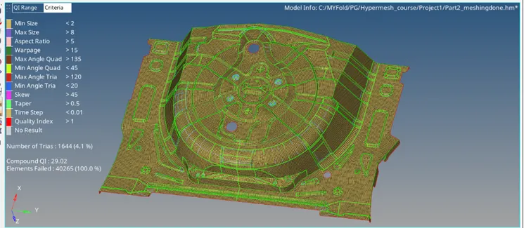
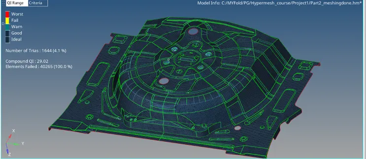
Conclusion: The given model was reviewed and proper geometry checks, cleanups, mid-surface extraction, and meshing were performed successfully and the final trias percentage was down to 4.1%.
The project provides a clear understanding of various operations done in the pre-processing stage for a given model.