Project 1 - Meshing of Floor Panel
AIM: To perform 2D meshing on given floor panel.
Objective:
- Geometry clean-up
- Mid-Surface extraction
- Mesh creation
- Quality check
- Assign thickness
Description:
The input file with. igs format is imported in ANSA to start creating the 2D mesh. It is a sheet metal component with 1mm thickness.
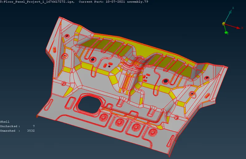
Geometry clean up:
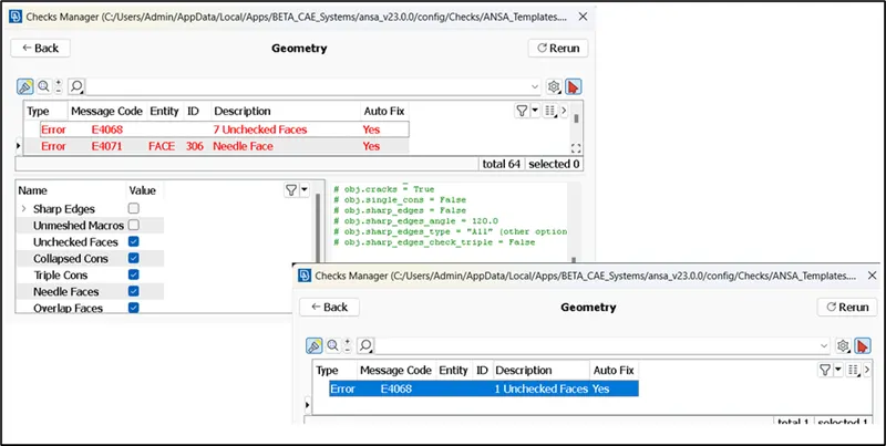
Firstly, the geometry is checked for any errors. Most of the errors can be fixed automatically and very few needs to be fixed manually.
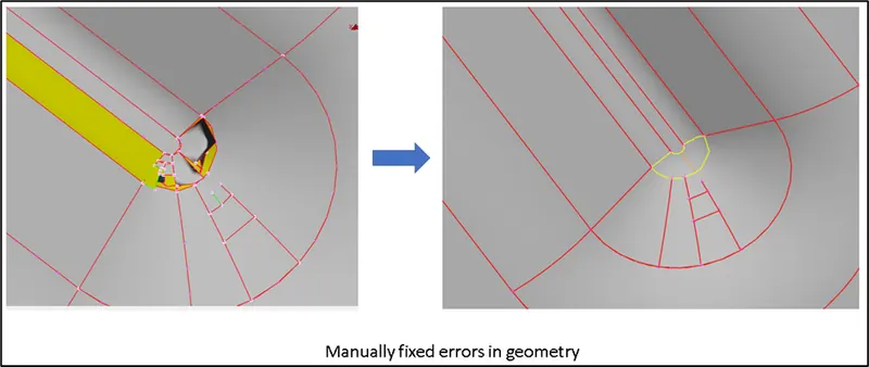
In the following picture, we can see the type of error that are fixed manually.
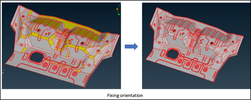
The orientation must be fixed to ensure we get the proper mid in the next stage.
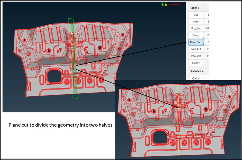
The geometry is then divided into two halves for ease of working.
TOPO>Faces>Plane Cut
Mid-surface extraction:
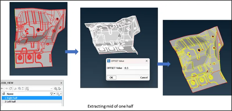
The half of panel is thus displayed and locked in a view. It is further added assigned a property.
By using Offset method, the mid of the displayed half is extracted as shown.
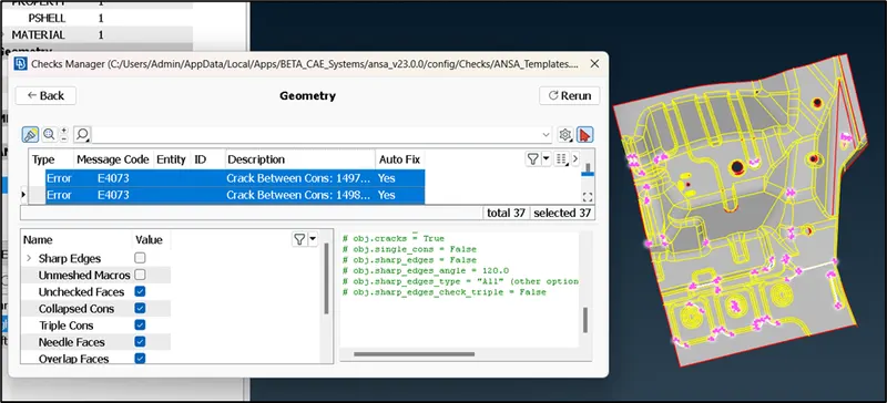
The mid surface is also checked for any geometry errors and then it is fixed.
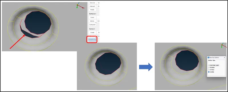
Some of the errors like shown below are fixed manually. The following error is fixed by using “Cons2curves” option, later deleted the error surface and then filled it with new face. Similarly, other errors are fixed.
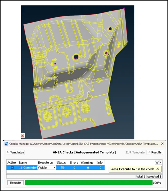
The geometry check is run again and all the errors in the visible geometry are fixed.
Meshing and quality check:
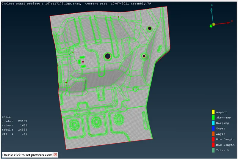
Using the “Best” mesh option, the meshing is done for this model and the result is as follows:
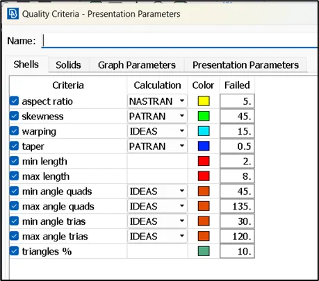
The quality of the mesh is fixed further to an extent where it cannot be done further by using the following quality criteria. The quality of the mesh is fixed by using following options:
MESH>Elements>Split
Mesh>Elements>Swap
MESH>Shell Mesh>Improve
MESH>Grids>Paste
MESH>Elements>New
MESH>Macros>Join
The areas where the close cons are present, the quality errors were left as is.
I tried to do a symmetry of the half that is fixed, but it was found that a lot of things needed to be reworked on the other half of the geometry as shown.
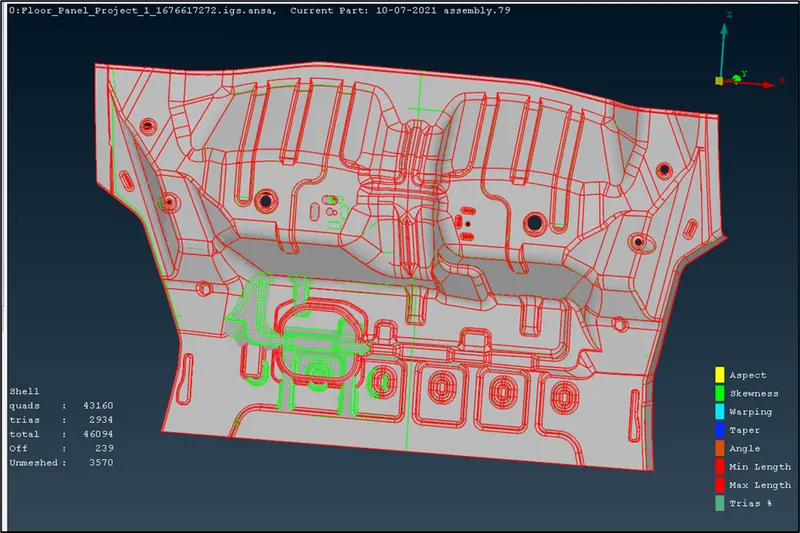
Instead of going with the above option of symmetry, I have done the similar steps on the other half of the geometry as it was done for the first half.
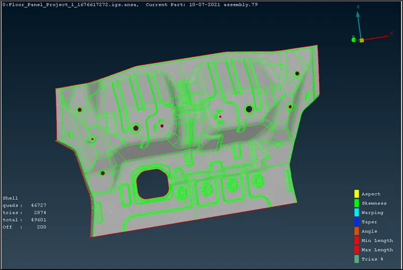
The quality errors were fixed in the second half of the geometry. By switching on both the mid surface geometry and mesh, the quality and mesh flow were addressed. The result of mesh is as shown in following image with some of the elements as off.
Assigning thickness:
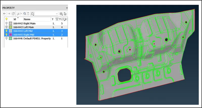
The thickness of the part is assigned to the properties and then it is put in “Draw shell as solid” mode.
Conclusion:
Thus, the 2D meshing of floor panel is performed.