Project - 1 : Meshing of a Plastic Component
AIM :
To generate 2D meshing for the given plastic model.
OBJECTIVES :
- For the given plastic model, check and resolve all the geometrical errors.
- Create a mid-surface for all the components.
- Generate 2D meshing for the mid-surface such that it clears all the provided quality criteria and the features in the model are captured properly with a good mesh flow.
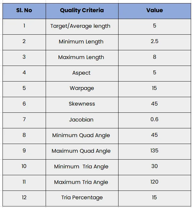
QUALITY CRITERIA :
PROCEDURE :
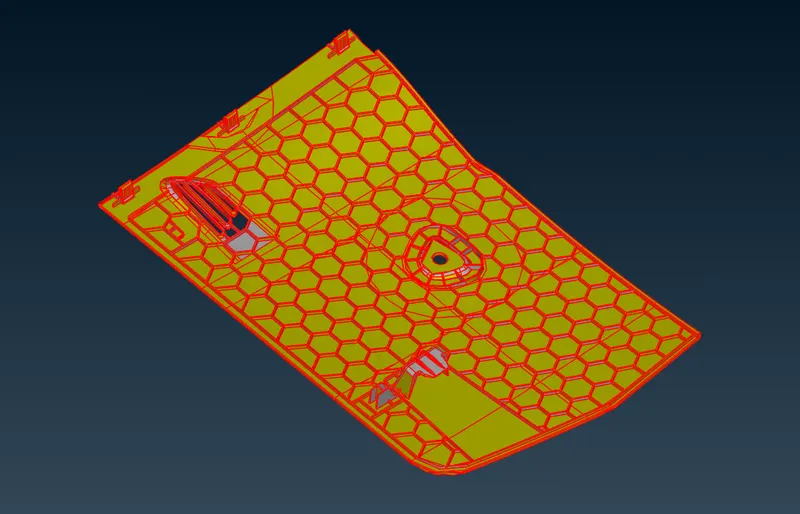
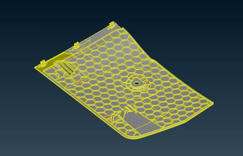
The first and foremost step in the procedure is importing the plastic model into ANSA. The imported geometry is as shown.
Geometry Cleanup :
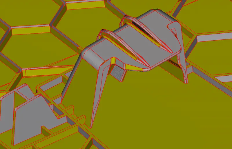
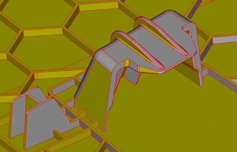
The first step in geometry cleanup of the model is increasing the resolution of the CONS such that all the features of the model are captured accurately. This is done by decreasing the node spacing value to a distance of 1 mm, by using the ‘perimeters – length’ function
Before Increasing CONS Resolution :
After Increasing CONS Resolution :
Throughout the geometry, we can observe that there are various single CONS present. In order to obtain connectivity between the surfaces and get rid of these single CONS, we use the ‘topo’ function.
Further, we orient the surfaces such that all the faces are towards a single normal direction (grey on the outside, yellow on the inside).
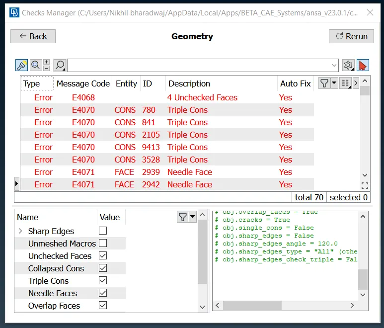
Finally, we run a geometry check to identify all the geometrical errors present in the geometry amd we further solve them by using the auto-fix function.
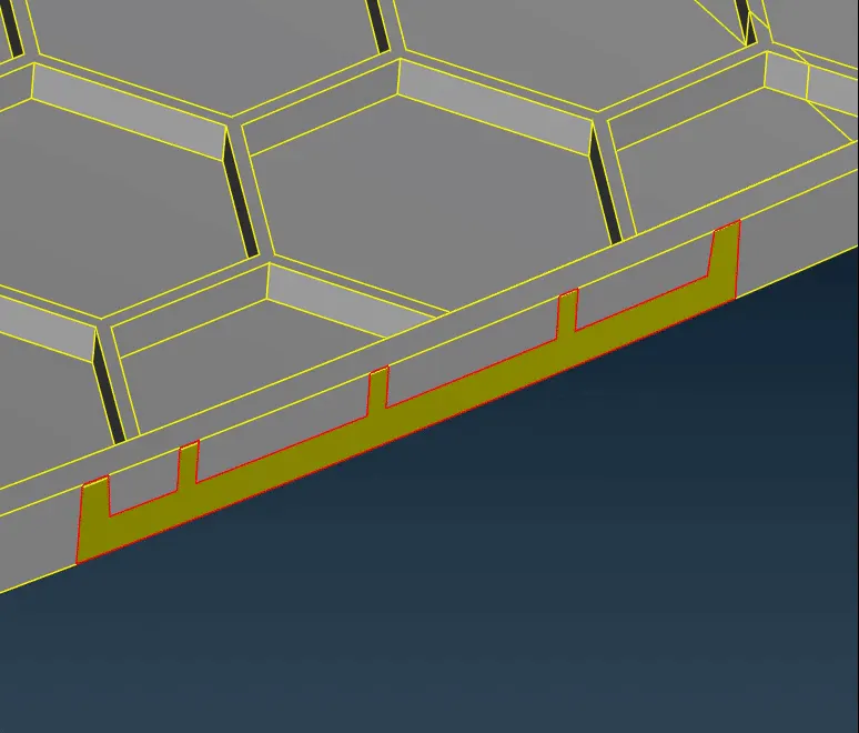
For few of the errors such as single CONS which cannot be resolved by the auto-fix function, we move on to manually resolve them. For the missing face as shown below, we use the ‘fill hole’ function to obtain a new surface for the same.
Casting Process :
After resolving all the geometrical errors of the model, we then move on to extract the mid-surface for the plastic model. For this particular model, we use the ‘casting’ method, which is an automatic meshing process where the mid-surface is automatically extracted as well as meshed in relevance to the provided target element length.
In order to maintain the mesh element quality of the casting, we first provide the quality criteria parameters.
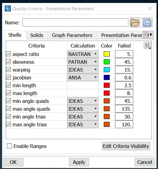
Next, we move on to generate the automatic middle mesh – that is the casting for the geometry. We provide the minimum thickness value as 0.5 and a target element length of 5 as shown.
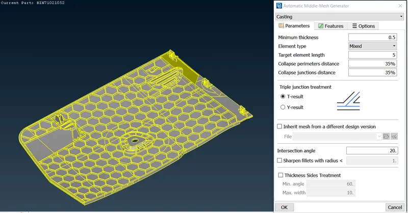
The casted surface along with the automatically generated surface mesh is obtained as follows. Corrections and error rectifications are needed to be carried out in order to obtain an accurate FE representation of the geometry.
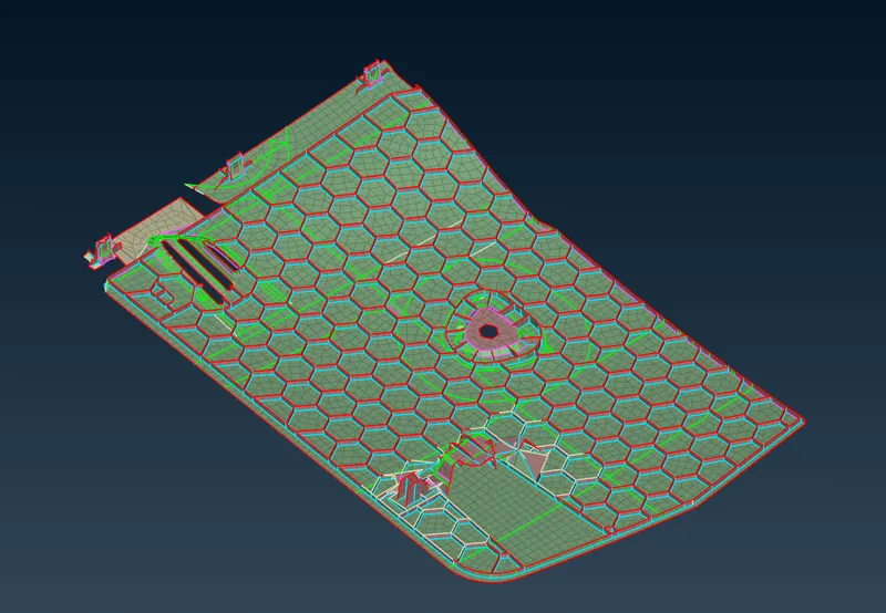
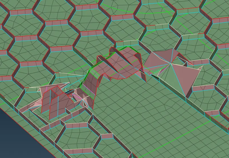
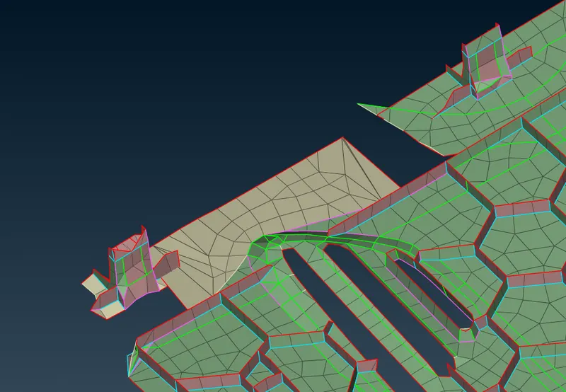
Regions Requiring Corrections :
For such surfaces, we either use the ‘align manager’ function to align the areas and perimeters according to the requirement, by comparison to the parent geometry or we rectify the respective error regions manually – by using the ‘fill’ function along with the help of the align manager entity.
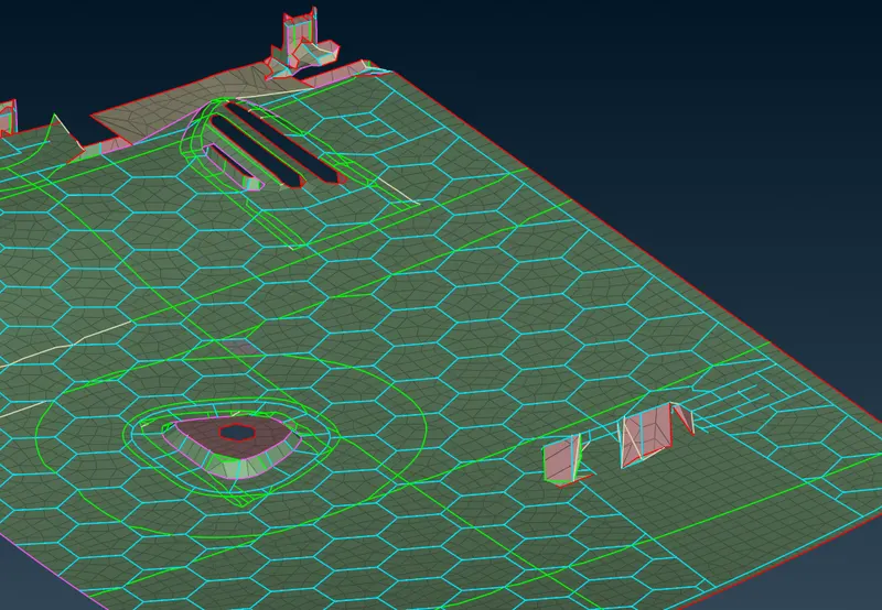
The final casting geometry – simplified and rectified of elemental errors is obtained as shown.
- Majority of the tria elements formed are resolved by using the ‘split’, ‘join’ and ‘paste’ commands, such that we obtain a smooth mesh flow.
- Rotating quads are avoided as much as possible and the meshing is smoothened in such a way so as to minimize elemental failures.
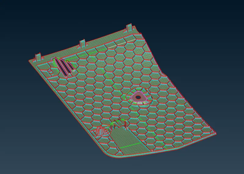
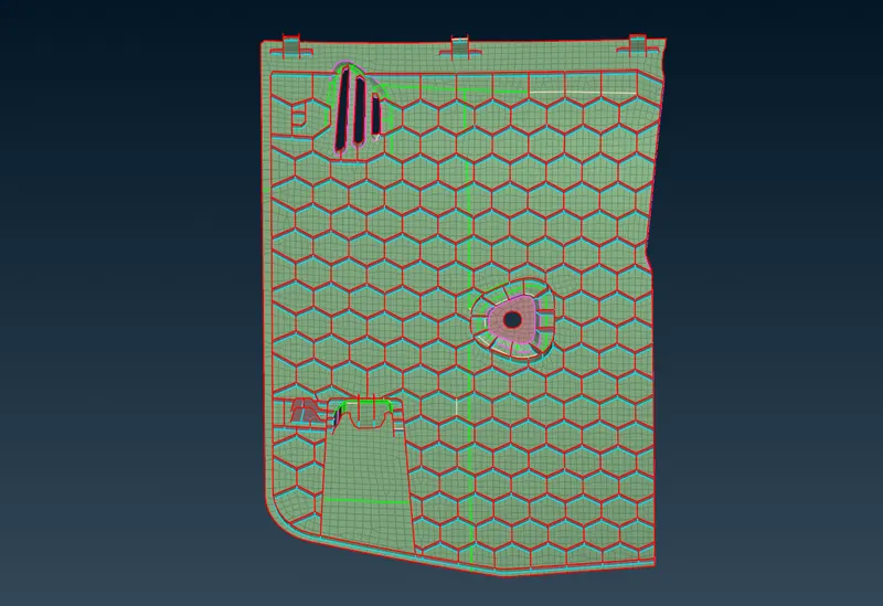
Complete Meshed Model View :
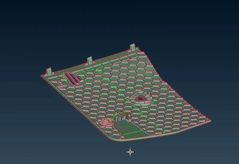
Thickness Assignment :
Finally, after obtaining the required FE element mesh, we then move on to assigning thickness values for the various components of the geometry. As different parts of the model are of different thicknesses, we create PID’s of that particular thickness values.
Thereby, the thickness values are assigned as follows.
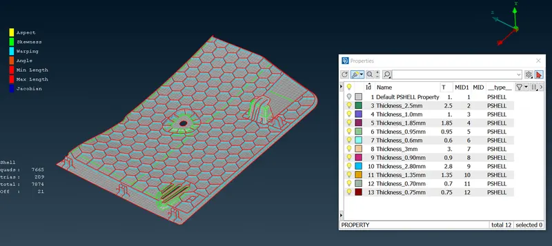
The PID view of the various assigned thicknesses is obtained as follows.
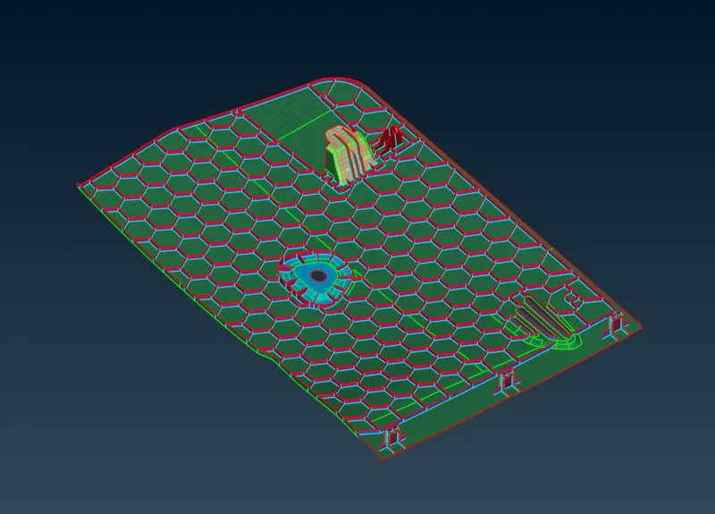
CONCLUSIONS :
For the given plastic component, geometry cleanup has been carried out and all the geometrical errors have been manually resolved as well as by using auto-fix.
2D mixed meshing has been generated for each section of the component such that a smooth mesh flow is obtained. The trias have been resolved as much as possible such that they do not fall on the feature lines, thereby obtaining our final FE mesh.
Each section of the meshed geometry has been assigned to their respective thickness values by creating PID’s for the same.
Geoemtry File : https://drive.google.com/file/d/1lMwbbUg4ZJWyEZS8IzzPpnGjz1QZgRJC/view?usp=share_link