Project 1 Mechanical design of battery pack
Mechanical Design of Battery Pack
Aim:
To design a battery pack arrangement with ANR26650M1-B cell for 18kWh capacity.
Cell used:
ANR26650M1-B
Battery pack capacity to design:
18 kWh
Designing:
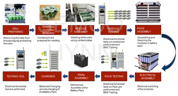
Process involved in design of Battery pack:
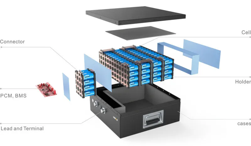
Disintegrated view of Battery pack:
Cell:
Lithium Werks ANR26650 cells are capable of delivering very high power due to its use of patented Nanophosphate battery technology.
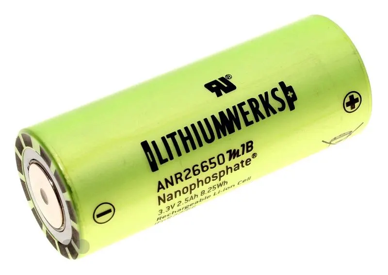
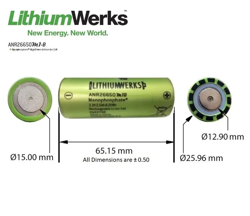
ANR26650 implies
N indicates Nanophosphate
R indicates cylindrical
26 indicates radius (or) width of cell
65 indicates length (or) height of cell
In this type of battery, graphite act as anode and Lithium Iron Phosphate act as cathode.
During discharging,
At anode,
`LiC_6 -> C_6 + Li^+ + e^-`
Anode gets oxidized and releases the electrons.
At Cathode:
`FePO_4 + Li^+ + e^-) -> LiFePO_4`
Cathode gets reduced with the absorption of electrons.
Overall reaction,
`FePO_4 + LiC_6 -> C_6 + LiFePO_4`
This process can be reversed while charging.
Based on lithium iron phosphate chemistry (LiFePO4), the cells are inherently safe over a wide range of temperatures and conditions.Whether the application requires outstanding cycle life or stable float reliability, these cells are suitable for a wide variety of power, pulse, or stand-by applications.
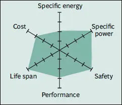
Nanophosphate battery technology offers stable chemistry, faster charging, consistent output, excellent cycle life and superior cost performance. It provides the foundation for safe systems while meeting the most demanding customer requirements. Multiple layers of protection are employed at the chemistry, cell and system level to achieve an energy storage solution with superior safety and abuse tolerance compared to metal oxide lithium-ion chemistries.
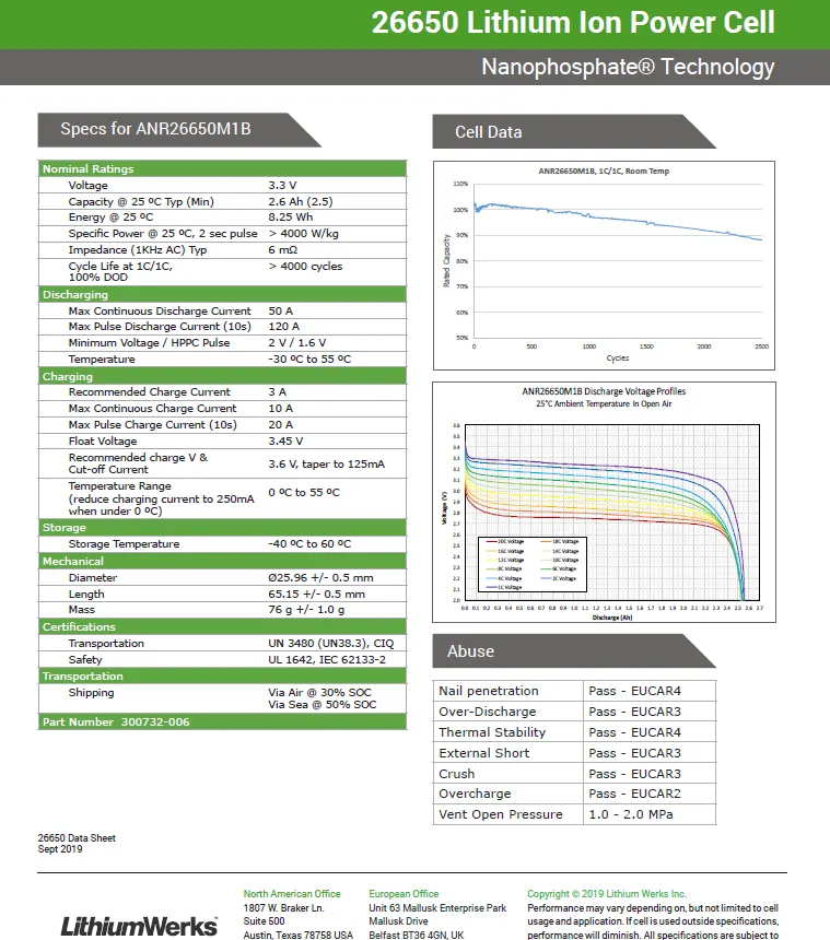
Datasheet of cell:
Cell Preparing:
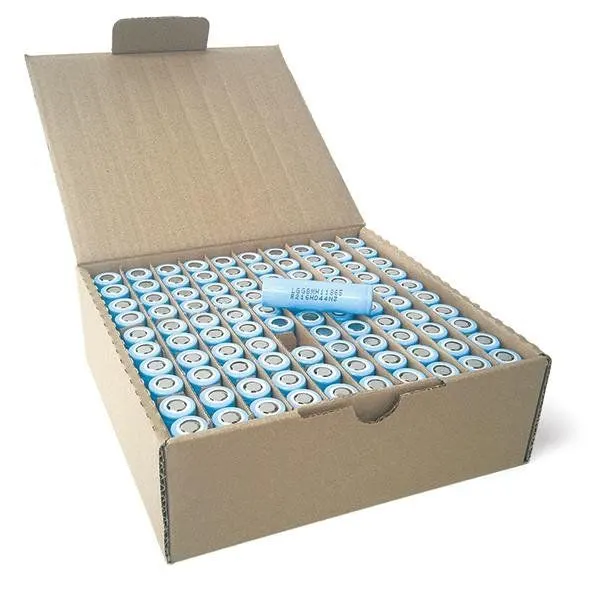
The cells are received from the manufacturer and it is removed from the package. And then the cells are tested for their properties, characteristics or for identification of any damaged cells during the transportation. If the battery pack manufacturer is also manufacturing the cell this process is neglected. Because the cells are tested while manufacturing itself.
Cell testing:
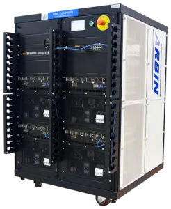
ARBIN cell testing equipment can test,
- Cell Voltage up to 10V.
- Cell Current up to 2500A.
- Ability to test up to 96 cells with a single chassis.
Tests done by cell testing equipment:
- Electrochemistry, Battery & Supercapacitor Testing
- Coulombic Efficiency (HPCE) Measurements
- Electric Vehicle (EV) Cell Testing
- Life Cycle Testing
- EIS (electrochemical impedance spectroscopy)
Electrical configuration or assembly:
The cells are assembled as per the specifications needed. The main parameters considered are Output voltage of battery pack, Specific capacity and Specific energy. According to the parameters required the cells are connected in series or parallel configuration.
Calculations:
Cells required:
Energy required = 18 kWh = 18000 Wh
Energy of one cell = 8.25 Wh
Number of cells required = 18000/8.25 = 2181.81
Number of cells required = 2182 cells
Let us consider the Output voltage of the battery pack is 300V
Voltage of the cell = 3.3V
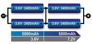
Voltage gets added when cells are connected in series and capacity remains same.
Example,

Number of cells in series = 300/3.3 = 90.9
Number of cells in series = 91 cells.
Total number of cells = Number of cells in series x Number of cells in parallel.
Number of cells in parallel = Total number of cells / Number of cells in series
= 2182/91 = 23.97
Number of cells in parallel = 24 cells.
When cells are connected in parallel the capacity gets added and voltage remains same.
Example,
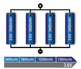
Capacity of the cell = 2.6Ah
When 24 cells are connected in parallel, the total capacity of the battery pack is 62.4Ah.
As per the calculation,
Total number of cells = 2184 cells
This will not have much impact in the battery and it is negligibly above requirement.
Hence the configuration is 91S 24P.
Our Battery pack has 303.3V, 62.4Ah
Example,
Placing of cells in Holder:

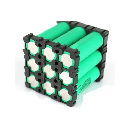
The cells are placed safely in the cell holder to avoid vibrations and is also insulated by giving the proper spacing between the cells for cooling.
Module connection:
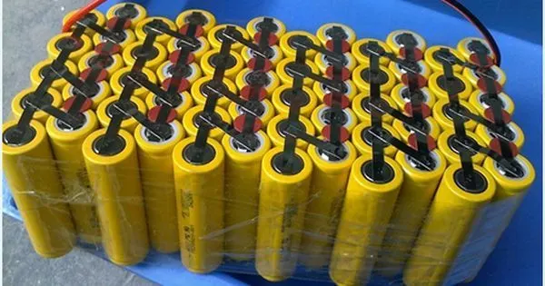
The cells are connected using the available connecters or the contact plates are prepared by terminal cutting (or bending) and is welded by laser or spot welding. The contact plates can be made of nickel. Some place is left for connecting the balancing connector from BMS to the positive terminal of the cells.
Thermal management:
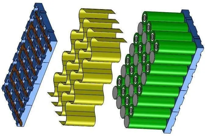
Heat spreaders contribute to balancing the thermal profile within Li-ion battery packs. Heat spreaders used in conjunction with heat sinks efficiently transfer heat away from the cells. Heat spreaders can be graphite sheets coated with thin dielectric films or thermally conductive metal foils. Since they are flexible, heat spreaders can weave between cells before terminating at heat sinks. It is passive cooling.
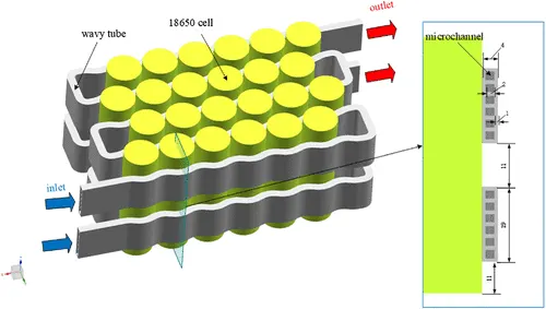
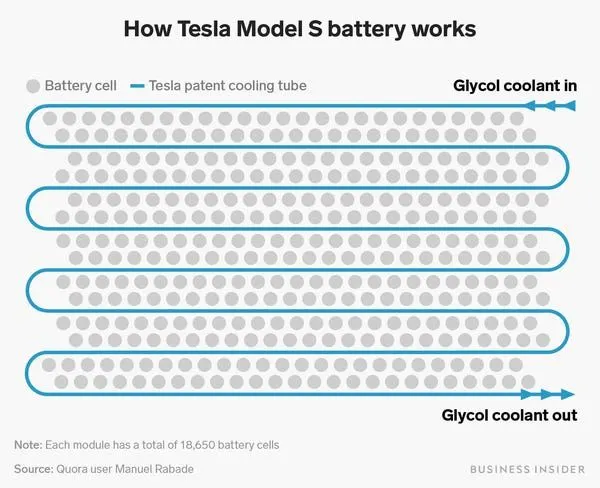
For active liquid the glycol can be used as coolant and is passed through the metal tube. Glycol collects the heat from the source and get cooled in heat exchanger and condensed in compressor and to battery, the cycle continues.
Module testing:
The module is tested for proper connection of cells, open circuit voltage, capacity and thermal runaway.
ARBIN module testing equipment performs,
- Life Cycle Testing
- Simulation of advanced real-world test profiles
- Cranking amp tests with discharge current up to thousands of amps.
Electrical assembly of modules:
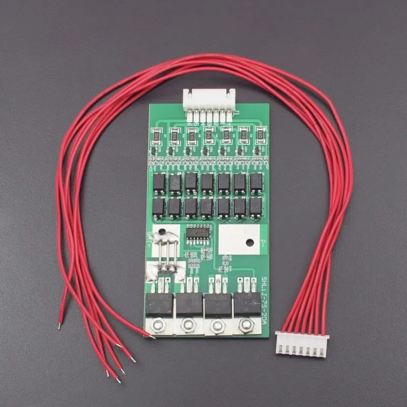
The modules are electrically connected according to the requirements. The fuses are also connected for each cell for safety. If any problem occurs, then the particular cell can be isolated without affecting the other cells in the pack. The sensors are connected from each cell to Battery management system to identify the cell voltage, capacity, state of charge and temperature. BMS mainly consists of one master controller and some other supporting (slave) controllers. Without Battery management system the cells become unbalanced. If the cells become unbalanced, the overall capacity, performance and lifespan gets reduced. It may result in failure of battery pack and explode. It is required to use Battery Management System for safety concern. It also used to distribute the load equally among the cells. Hence the overall capacity and the range also increased. And the battery can be used efficiently. It is also used to estimate the State of Charge and State of Health of the battery. The Balancing connector from all positive terminal of the cells is connected to BMS with one negative terminal or from all negative terminals of the cell is connected to BMS with one positive terminal. The BMS is closely attached to the module.
BMS with balance connector:
Battery pack with BMS:
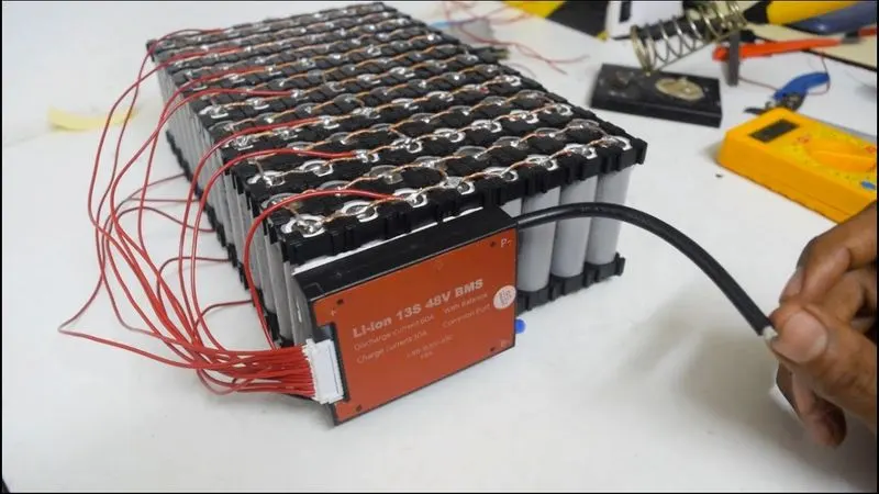
In the above example left side connections are balancing lead. And in the BMS the P- and P+ are connected to load through the power converters.
Example of Balance connectors connection diagram:
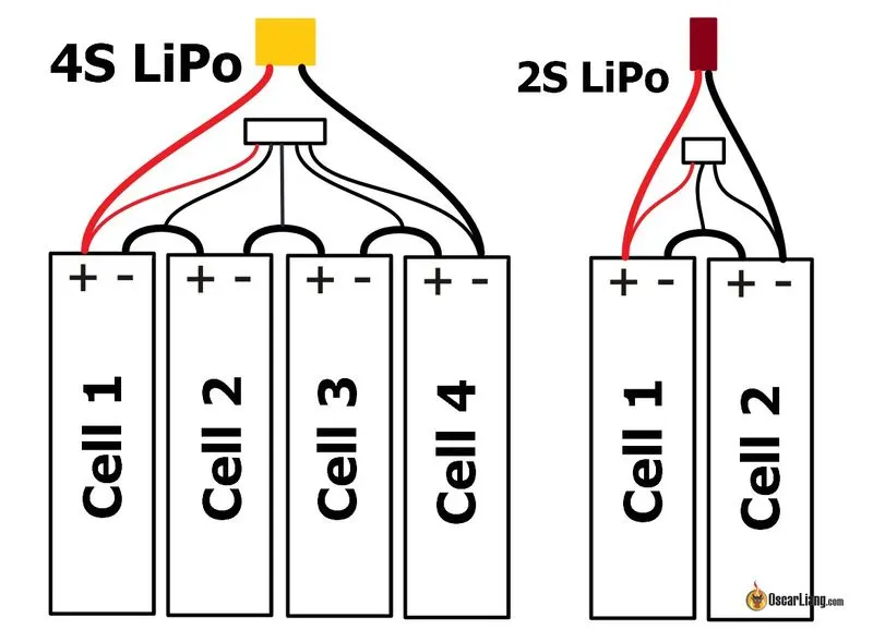
*Thin wires are balancing connectors (leads)
*Thick wires are load leads which is connected to Battery pack through BMS.
Final Mechanical Housing of Battery module:
The battery module with BMS is enclosed by a metallic cover and is sealed to prevent is from the dust, water and other environmental materials that affects the battery life. The enclosing material should be hard enough and should not corrode or break.
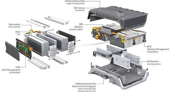
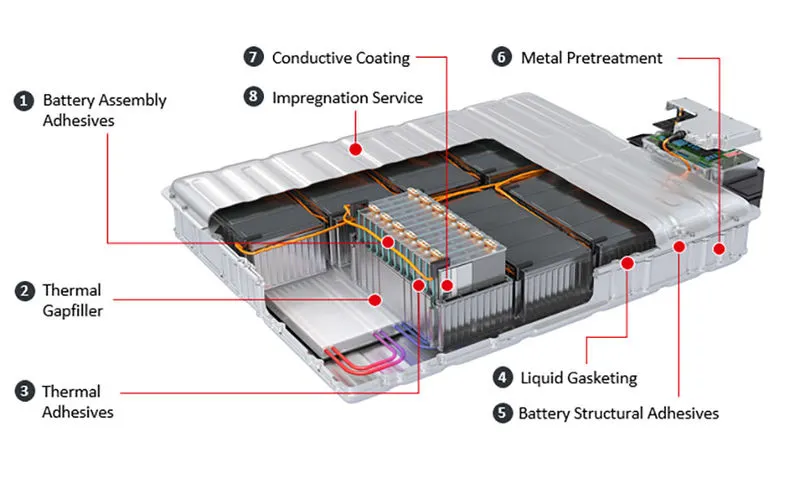
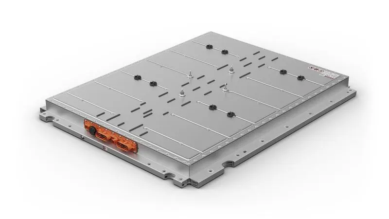
The last image is the final look of battery pack.
Testing of Battery pack:
The battery pack is tested by completely charging and discharging and analyze the parameters, characteristics and Thermal management. It may also go through some torture tests.
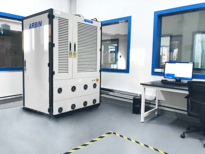
This equipment can test the battery pack of upto 1000V and the maximum power upto 1MW. Arbin is one of the leading testing equipment manufacturer in the world.
The Arbin Battery pack testing equipment performs,
- Life Cycle Testing
- Electric Vehicle (EV) Drive Cycle Simulations
- Hybrid Pulse Power Characterization Test – HPPC
- Dynamic Stress Test – DST
- Worldwide Harmonized Light Vehicles Test Procedure – WLTP
- Cranking Amp Tests
- Validate internal battery management system via CAN Bus.
Placement of Battery pack in Electric vehicle:
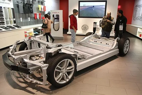
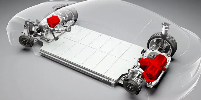
Then the Battery pack are placed in the vehicle according to the construction and the space allocated for battery packs.
Some of the examples for actual placement of Battery in Vehicle.
MG ZS EV:
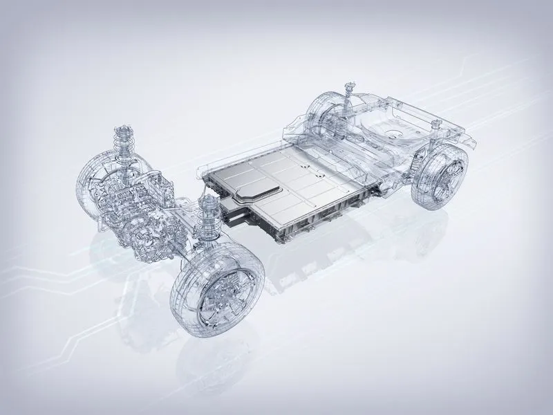
TESLA Model 3
Battery pack:
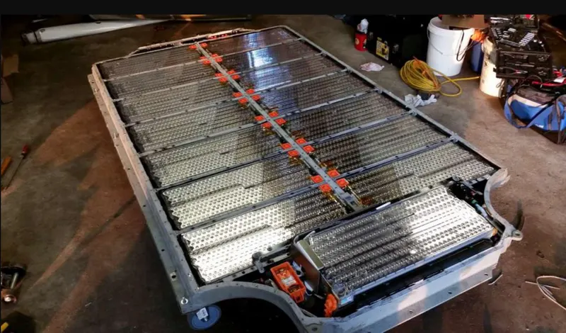
Housing of Battery pack and Chassis:
Placement of Battery pack and Powertrain:
Summary:
The battery pack design is the most important in the case of Battery operated Electric Vehicles (BEV). The charging and discharging should be followed by standards. The quick charging must be used only when it is urgently required. It may reduce the lifetime of the battery. The home charging must be done with the proper provided charger from the manufacturer to secure the battery life. Many research and experiments under process in battery technology to increase the capacity and energy to increase the range of the vehicle.
Smart EQ can go upto 95.5 kms range with this 18 kWh battery on a single charge.