Mechanical design of battery pack
AIM:
To prepare a detailed battery pack drawing along with its enclosure and state the assumptions.
Battery pack capacity: 18 kWh
Cell: ANR26650M1-B
THEORY:
A lithium-ion (Li-ion) battery is an advanced battery technology that uses lithium ions as a key component of its electrochemistry. During a discharge cycle, lithium atoms in the anode are ionized and separated from their electrons. The lithium ions move from the anode and pass through the electrolyte until they reach the cathode, where they recombine with their electrons and electrically neutralize. The lithium ions are small enough to be able to move through a micro-permeable separator between the anode and cathode. In part because of lithium’s small size (third only to hydrogen and helium), Li-ion batteries are capable of having a very high voltage and charge storage per unit mass and unit volume.
Li-ion batteries can use several different materials as electrodes. The most common combination is that of lithium cobalt oxide (cathode) and graphite (anode), which is most commonly found in portable electronic devices such as cellphones and laptops. Other cathode materials include lithium manganese oxide (used in hybrid electric and electric automobiles) and lithium iron phosphate. Li-ion batteries typically use ether (a class of organic compounds) as an electrolyte.
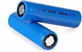
The Basics-
A battery is made up of an anode, cathode, separator, electrolyte, and two current collectors (positive and negative). The anode and cathode store the lithium. The electrolyte carries positively charged lithium ions from the anode to the cathode and vice versa through the separator. The movement of the lithium ions creates free electrons in the anode which creates a charge at the positive current collector. The electrical current then flows from the current collector through a device being powered (cell phone, computer, etc.) to the negative current collector. The separator blocks the flow of electrons inside the battery.
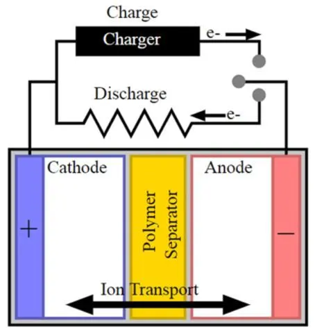
CHARGE/DISCHARGE
While the battery is discharging and providing an electric current, the anode releases lithium ions to the cathode, generating a flow of electrons from one side to the other. When plugging in the device, the opposite happens: Lithium ions are released by the cathode and received by the anode.
Advantages of Li-ion batteries -
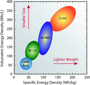
Compared to the other high-quality rechargeable battery technologies (nickel-cadmium or nickel-metal-hydride), Li-ion batteries have several advantages. They have one of the highest energy densities of any battery technology today (100-265 Wh/kg or 250-670 Wh/L). In addition, Li-ion battery cells can deliver up to 3.6 Volts, 3 times higher than technologies such as Ni-Cd or Ni-MH. This means that they can deliver large amounts of current for high-power applications, which has Li-ion batteries are also comparatively low maintenance and do not require scheduled cycling to maintain their battery life. Li-ion batteries have no memory effect, a detrimental process where repeated partial discharge/charge cycles can cause a battery to ‘remember’ a lower capacity. This is an advantage over both Ni-Cd and Ni-MH, which display this effect. Li-ion batteries also have a low self-discharge rate of around 1.5-2% per month. They do not contain toxic cadmium, which makes them easier to dispose of than Ni-Cd batteries.
Due to these advantages, Li-ion batteries have displaced Ni-Cd batteries as the market leader in portable electronic devices (such as smartphones and laptops). Li-ion batteries are also used to power electrical systems for some aerospace applications, notable in the new and more environmentally friendly Boeing 787, where weight is a significant cost factor. From a clean energy perspective, much of the promise of Li-ion technology comes from its potential applications in battery-powered cars. Currently, the bestselling electric cars, the Nissan Leaf and the Tesla Model S, both use Li-ion batteries as their primary fuel source.
Limitations of Li-ion batteries -
Despite their technological promise, Li-ion batteries still have several shortcomings, particularly with regards to safety. Li-ion batteries tend to overheat and can be damaged at high voltages. In some cases, this can lead to thermal runaway and combustion. This has caused significant problems, notably the grounding of the Boeing 787 fleet after onboard battery fires were reported. Because of the risks associated with these batteries, several shipping companies refuse to perform bulk shipments of batteries by plane. Li-ion batteries require safety mechanisms to limit voltage and internal pressures. This can increase weight and limit performance in some cases. Li-ion batteries are also subject to aging, meaning that they can lose capacity and frequently fail after several years. Another factor limiting their widespread adoption is their cost, which is around 40% higher than Ni-Cd. Addressing these issues is a key component for current research into the technology. Finally, despite the high energy density of Li-ion compared to other kinds of batteries, they are still around a hundred times less energy-dense than gasoline (which contains 12,700 Wh/kg by mass or 8760 Wh/L by volume).
Now let us look into the cell with which we need to design a battery pack.
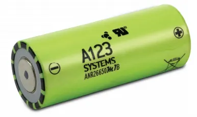
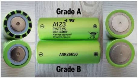
Nanophosphate® High Power LithiumIon Cell ANR26650M1-B
A123’s high-performance Nanophosphate® lithium iron phosphate (LiFePO4) battery technology delivers high power and energy density combined with excellent safety performance and extensive life cycling in a lighter weight, more compact package. The cells have a low capacity loss and impedance growth over time as well as high usable energy over a wide state of charge (SOC) range, allowing the systems to meet end-of-life power and energy requirements with minimal pack oversizing.
Applications-
COMMERCIAL SOLUTIONS
Advanced lead-acid replacement batteries for:
- Datacenter UPS
- Telecom backup
- IT backup
- Autonomously guided vehicles (AGVs)
- Industrial robotics and material handling equipment
GOVERNMENT SOLUTIONS
- Military vehicles
- Military power grids
- Soldier power
- Directed energy
GRID SOLUTIONS
- Frequency regulation
- Renewables integration
- Reserve capacity
- Transmission and distribution
TRANSPORTATION SOLUTIONS
Hybrid, plug-in hybrid, and electric vehicle battery systems for:
- Commercial vehicles
- Off-highway vehicles
- Passenger vehicles
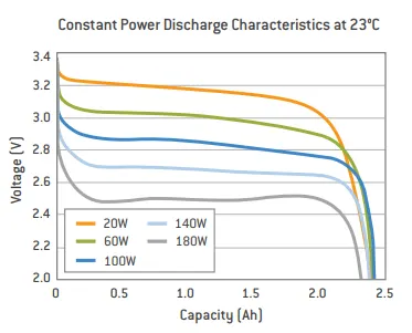
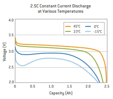
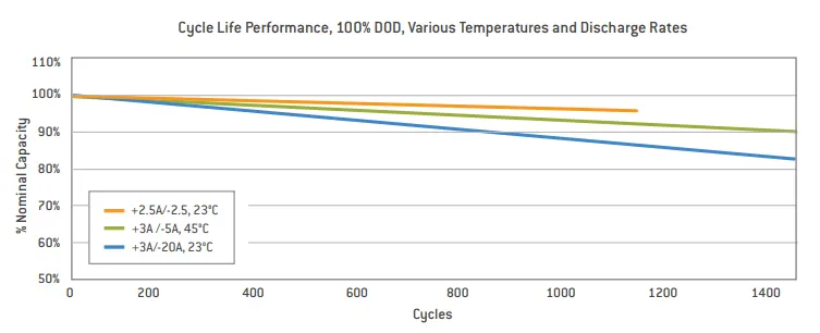
The below images show the power discharge, current discharge, and the life cycle performance of this Nanophosphate Lithium-ion cell.
DESIGN CALCULATIONS -
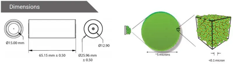
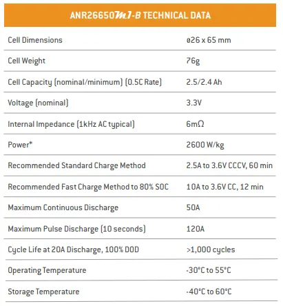
The parameters of this cell according to the datasheet are shown below.
Before going into the mechanical design of the battery pack, let us look into the theory behind it.
The purpose of a battery pack is to provide a convenient integrated power source for portable applications. The pack may fulfill several functions:-
- It enables higher voltage or higher capacity batteries to be built up from low voltage, low capacity cells.
- It houses a cell or a bank of cells together with the associated interconnections in a single convenient package.
- It accommodates any necessary monitoring and electronic protection devices or circuits within the pack.
- It can accommodate additional circuitry such as indicator lights, heaters, cooling ducts, and solar panels.
- It matches and meshes with the cavity in the product which the battery is intended to power providing both electrical and mechanical interfaces.
- It can provide unique electrical and mechanical interfaces to ensure compatibility both of the battery with the intended product and the charger with the battery.
Capacity and Voltage -
With a simple series chain of cells, the battery capacity in amp-hours is the same as the capacity of the individual cells since the current flows equally through all the cells in the chain. High battery voltages are achieved by adding more cells in a series chain. The voltage of the battery is the voltage of a single cell multiplied by the number of cells in the chain. This does not increase the amp-hour capacity of the battery, but it increases the WattHour capacity, or the total stored energy, in proportion to the number of cells in the chain.
Battery capacity can be increased by adding more parallel cells. This increases the amp-hour capacity as well as the WattHour capacity without increasing the battery voltage. For batteries with parallel chains, the capacity of the battery is the capacity of the individual chain multiplied by the number of parallel chains.
Whereas cell voltage is fixed by the cell chemistry, cell capacity depends on the surface area of the electrodes and the volume of the electrolyte, - that is, the physical size of the cell. If at all possible the number of cells in a pack should be minimized to simplify the design and to minimize potential reliability problems. Fewer cells require fewer support electronics. Thus parallel chains should be avoided by specifying the highest capacity cells available.
Pack Design Options -
The design of the outer package or housing of the battery depends to a great extent on the components it has to accommodate and the physical protection it has to provide for them. These components are not just the cells, but also protection devices, electronic circuits, interconnections, and connectors which must all be specified before the final battery case can be designed. For high power, high energy batteries robust packaging is required for safety reasons.
Cell configuration -
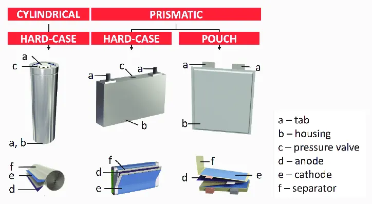
The ultimate shape and dimensions of the battery pack are mostly governed by the cavity which is planned to house it within the intended application. This in turn dictates the possible cell sizes and layouts which can be used. Prismatic cells provide the best space utilization, however, cylindrical cells provide simpler cooling options for high-power batteries. The use of Pouch cells provides the product designer more freedom in specifying the shape of the battery cavity permitting very compact designs. The orientation of the cells is designed to minimize the interconnections between the cells.
Battery Electronics -
Besides the cells, many battery packs now incorporate associated electronic circuits. These may be protection devices and circuits, monitoring circuits, charge controllers, fuel gauges, and indicator lights. Electronics for high-power multi-cell packs also include cell balancing and communications functions. The packs may also be designed to deliver more than one voltage from the basic cell combination, although applications requiring multiple voltage sources are more likely to make provision for this within the application. In addition to the basic battery support electronics, the battery pack may include other functions such as heaters to extend the lower working temperature or solar cells to keep the battery fully charged. These circuits in turn have their own control circuits. Space, fixing points and methods, and interconnections need to be allocated for all these electronic circuits.
Software -
Sofware is a major component of Lithium batteries, particularly for automotive applications. Control systems are required to keep the cells within their specified operating range and to protect them from abuse. Fuel gauging needs complex algorithms to estimate the state of charge (SOC). Communications with other vehicle systems are needed for monitoring the battery status and controlling energy flows.
Internal Connections -
Low power cells are usually connected using nickel strips which are welded to the cell terminals or the case. Soldering is not recommended since the soldering process is apt to apply large, uncontrolled amounts of heat to the battery components which may damage the separators or the vents which are normally made of plastic. Modern computer-controlled resistance welders allow much more precise control of the welding process, both limiting the amount of heat applied to the battery and localizing the heat to a small desired area. Welding also provides a stronger, low resistance joint. The interconnecting strips often have complex shapes and profiles which may be stamped out of the flat strips in a progressive die. High power cells may use solid copper bus bars or braided straps. The electronic components are usually mounted on a conventional printed circuit board (PCB).
Flexible PCBs may cost more than rigid PCBs but they can be used to reduce the overall product costs. Not only do they save weight and space but they also provide more packaging options and they simplify physical interconnections and assembly operations as well as eliminating the need for connectors. Connectors may in fact be specified to facilitate assembly and disassembly if the design requires that individual battery components need to be changed or serviced but there is usually a cost and reliability penalty associated with such designs.
External Connections -
The type of terminals or connections to the external circuits depend on, the current to be carried, the frequency with which the battery may be connected and disconnected, and the design of the circuit to which the battery will be connected.
For low power circuits, gold plated contacts are the terminals of choice for connectors that are subject to frequent insertions. Gold is hard-wearing, it has low contact resistance and doesn't oxidize. Flying leads with spade terminals or snap-on studs are also used for low power applications. Metal tabs are also used on pouch cells.
Terminals for high-power applications are usually threaded metal studs to ensure a reliable connection. Safety requirements on high voltage batteries may also dictate shrouded terminals to prevent accidental exposure of the operator to dangerous voltages or of the battery to short circuits. Keyed or terminals or connections are also advisable to prevent connection to incorrect charges or loads.
Thermal Design -
Thermal management is a major issue in high-power designs, particularly for automotive applications. As part of the battery system, it may be necessary to provide air or water cooling ducts, pumps or fans, and heat exchangers for high temperature working or heaters for operating in low-temperature environments. The layout of the cells should be conducive to managing heat flows within the pack
Battery Packaging -
The battery casing has to provide the mechanical and electrical interfaces to the product it is designed to power as well as to contain all the components outlined above.
The simplest and least expensive packaging for small batteries is shrink wrap or vacuum-formed plastic. These solutions are only possible if the battery is intended to be completely enclosed by the finished product.
Injection-molded plastics are used to provide more precision packs. For enclosed packs designs using a minimum of materials are based around which a plastic frame holds the components in place thus minimizing the cost, the weight, and the size of the pack. The overall product cost can be further reduced by using insert moldings in which the interconnection strips and the terminals are molded into the plastic parts to eliminate both materials and assembly costs. Overmolding may also be used to encapsulate and protect small components or sub-assemblies.
In some designs, the battery pack forms part of the outer case of the end product. The colors and textures of the plastic must match the plastics of the rest of the product even though they may come from a completely different supplier. These designs are usually required to incorporate a mechanical latch to hold the battery in place. Again this latch as well as the terminals must interface with plastic parts from a different supplier so high precision and tight tolerances are essential. ABS polymers are the materials typically used for this purpose.
Batteries for traction applications are usually very large and heavy and subject to large physical forces as well as vibrations so substantial fixings are required to hold the cells in place. This is particularly necessary for batteries made up of pouch cells which are vulnerable to physical damage. Automotive battery packs must also withstand abuse and possible accidental damage so metal casings will normally be specified. The metal pack casing also serves to confine any incendiary event resulting from the failure of a cell or cells within the battery and to provide a measure of protection for the user. At the same time, the case must also protect the cells and the electronics from the harsh operating environments of temperature extremes, water ingress, humidity, and vibration in which these batteries work. Usually, the complete pack is replaced when the battery has reached the end of its useful life. In certain circumstances, however, for instance, when the pack incorporates a lot of electronic circuits, it may be desirable to design the pack such that the cells within the pack can be replaced. If the design requires provision for replacement of the cells the casing of the battery pack must be designed to clip or screw together. Normally the parts of the plastic housing will be ultrasonically welded together both for security and for low cost as well as to prevent unauthorized tampering with the cells and the electronics.
Identification
The pack design must incorporate some form of identification to indicate the manufacturer's name, the cell chemistry, the voltage, and the capacity as well as the country of manufacture. Most manufacturers will also include a date stamp and or serial number to assist traceability in case of problems. This information is usually provided on a label but it may also be printed directly onto the battery casing.
PROCEDURE -
The energy capacity of the battery pack that is designed will be 18kWh.
All high voltage battery packs are made up of battery cells arranged in strings and modules. A battery cell can be regarded as the smallest division of the voltage.
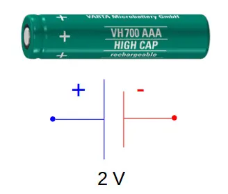
Individual battery cells may be grouped in parallel and/or series as modules. Further, battery modules can be connected in parallel and/or series to create a battery pack. Depending on the battery parameters, there may be several levels of modularity.
The total battery pack voltage is determined by the number of cells in series. For example, the total (string) voltage of 6 cells connected in series will be the sum of their individual voltage.
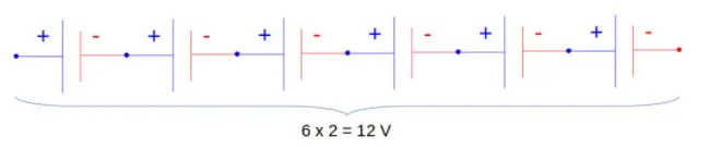
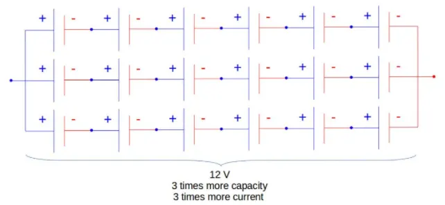
To increase the current capability of the battery capacity, more strings have to be connected in parallel. For example, 3 strings connected in parallel will triple the capacity and current capability of the battery pack.
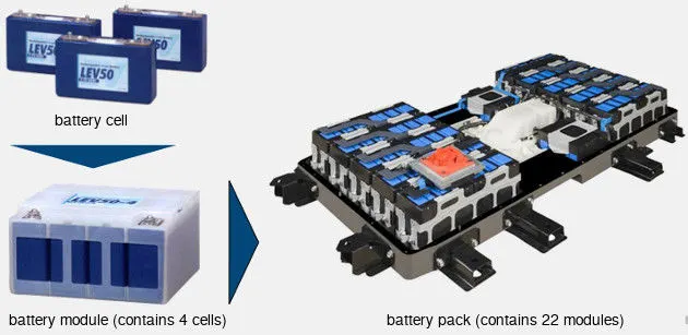
The high voltage battery pack of Mitsubishi i-MiEV consists of 22 modules made up of 88 cells connected in series. Each module contains 4 prismatic cells. The voltage of each cell is 3.7 V and the total voltage of the battery pack 330 V.
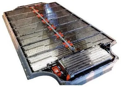
Another example is the high voltage battery pack of Tesla Model S, which has:
- 74 cells in a parallel-group
- 6 groups in series for a module
- 16 modules in series
- 7104 cells in total
Based on the cell parameters provided by the manufacturers, we can calculate the energy content, volume, gravimetric density, and volumetric density for each cell. We can use the data provided by the manufacturer from the datasheet.
The calculations will be done as shown below.
1. Volume of each cell -
Cylindrical cells, Vcc [m3]
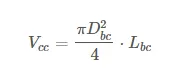
where `D_(bc)` - Battery Cell diameter and `L_(bc)` - Battery cell length
From the datasheet specifications shown above, we know that, `D_(bc) =26 mm = 0.026 m` and `L_(bc)=65 mm=0.065 m`
Substituting these values in the above equation, we get,
`V_(Cc) = (pi*0.025^2.0.065)/4 = 3.5 xx10^-5 m^3`
The volume of each cell is 35 mm^3.
2. Battery Cell Energy -
The battery cell energy Ebc [Wh] is calculated as:
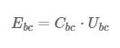
where `C_(bc)` - is the battery cell capacity and `U_(bc)` - Battery cell voltage
From the datasheet specifications shown above, `C_(bc) = 2.5Ah` and `U_(bc) = 3.3 V`
Substituting these values in the above equation we get,
`E_(bc)=2.5xx3.3=8.25Wh`
The battery cell energy is 8.25Wh.
3. Battery Cell Energy Density -
- Volumetric energy density, uV [Wh/m3]
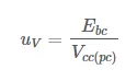
Substituting the above calculated values in the equation, we get,
`u_V=E_(bc)/V_(Cc) = 8.25/(3.5xx10^-5)=235714.3Wh//m^3`
The volumetric energy density is 235.714 kWh/m^3.
- Gravimetric energy density, uG [Wh/kg]
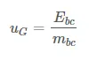
Substituting the above calculated values in the equation, we get,
`u_G=E_(bc)/m_(bc)=8.25/0.076=108.55 Wh//kg`
The gravimetric energy density is 108.55 Wh/m^3.
With the above cell parameters and the core requirements for the battery, we calculate the main parameters of the high voltage battery.
4. Total energy of Battery Pack -
The total energy of the battery pack which is required is given as 18kWh.
`E_(bp)=18000Wh`
5. Number of cells connected in series (`N_(cs)`) -
It is calculated by dividing the nominal battery pack voltage Ubp [V] by the voltage of each battery cell Ubc [V]. The number of strings must be an integer. Therefore, the result of the calculation is rounded to the higher integer.
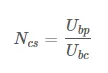
Let us assume that the battery pack voltage which is required to be 330V and the nominal voltage of the battery as per the datasheet is given as 3.3V.
`N_(cs)=U_(bp)/U_(bc)=330/3.3=100`
The total number of cells to be connected in series is 100.
6. Energy Content of a string -
The product between the number of battery cells connected in series Ncs and the energy of a battery cell Ebc [Wh].
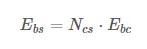
Substituting the above-calculated values, we get,
`E_(bs)=N_(cs)*E_(bc)=100xx8.25=825Wh`
The energy content in a string of cells connected in series is 825 Wh.
7. Number of strings in the battery pack -
It is calculated by dividing the nominal battery pack voltage Ubp [V] by the voltage of each battery cell Ubc [V]. The number of strings must be an integer. Therefore, the result of the calculation is rounded to the higher integer.
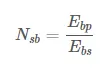
Substituting the above values, we get,
`N_(sb)=E_(bp)/E_(bs)=18000/825=21.81`
The total number of strings of 100 cells connected in series will be 22.
All the 22 strings will be connected parallelly with each other.
8. Battery Pack Capacity -
It is calculated as the product between the number of strings Nsb and the capacity of the battery cell Cbc [Ah].
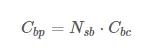
Substituting the above values, we get,
`C_(bp)=N_(sb)*C_(bc) =22xx2.5=55Ah`
The total capacity of the battery pack is 55 Ah.
9. Total number of cells of the battery pack -
It is calculated as the product between the number of strings Nsb and the number of cells in a string Ncs.
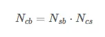
Substituting the above values, we get,
`N_(cb)=N_(sb)*N_(cs)=22xx100=2200`
The total number of cells required for designing the battery pack is 2200.
The size and mass of the high voltage battery are very important parameters to consider when designing a battery electric vehicle (BEV). For simplicity, we are going to calculate the volume of the battery pack considering only the battery cells. In reality, there are other factors to consider, like electronic circuits, cooling circuits, battery casing, wiring, etc.
10. Mass of the battery pack -
It is the product between the total number of cells Ncb and the mass of each battery cell mbc [kg].
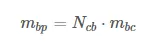
Substituting the above values, we get,
`m_(bp)=N_(cb).m_(bc) =2200xx0.076=167.2 kg`
The total mass of the battery pack will be 167.2 kg.
11. Volume of the battery pack -
It is the product between the total number of cells Ncb and the mass of each battery cell Vcc [m3]. This volume is only used to estimate the final volume of the battery pack since it does not take into account the auxiliary components/systems of the battery.
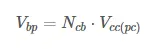
Substituting the above values, we get,
`V_(bp)=N_(cb).V_(Cc)=2200xx3.5xx10^-5=0.077m^3`
The total volume of the battery pack is 77000 mm^3.
12. String Peak Current -
It is the product between the peak C-rate of the battery cell C-ratebcp [h-1] and the battery cell capacity Cbc [Ah].
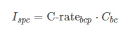
From the datasheet, the battery pack peak C-rate is 24 and the nominal capacity is 2.5Ah.
`I_(spc)=C-rate_(bcp).C_(bc) = 24xx2.5=60A`
The peak current achieved in the string is 60A.
13. Battery Pack peak current -
It is the product between the string peak current Ispc [A] and the number of strings of the battery pack Nsb.
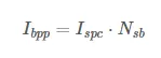
Substituting the above values, we get,
`I_(bpp)=I_(spc).N_(sb)=60xx22=1320A`
The peak current achieved in the battery pack is 1320A.
14. Battery Pack peak power -
It is the product between battery pack peak current Ibpp [A] and the battery pack voltage Ubp [V].
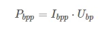
Substituting the above values, we get,
`P_(bpp)=I_(bpp).U_(bp)=1320xx330=435600W`
The battery pack's peak power will be 435.6 kW.
15. String continuous current -
It is the product between the continuous C-rate of the battery cell C-ratebcc [h-1] and the battery cell capacity Cbc [Ah].
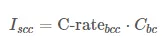
From the datasheet, the battery pack continuous C-rate is 10 and the nominal capacity is 2.5Ah.
`I_(sCc)=C-rate_(bCc).C_(bc)=10xx2.5=25A`
The continuous current achieved in the string is 25A.
16. Battery pack continuous current -
It is the product between the string continuous current Iscc [A] and the number of strings of the battery pack Nsb.
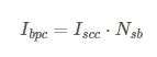
Substituting the above values, we get,
`I_(bpc)=I_(sCc)*N_(sb)=25xx22=550 A`
The continuous current achieved in the battery pack is 550 A.
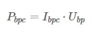
17. Battery pack continuous power -
It is the product between battery pack continuous current Ibpc [A] and the battery pack voltage Ubp [V].
Substituting the above values, we get,
`P_(bpc)=I_(bpc).U_(bp)=550xx330=181500W`
The battery pack's continuous power will be 181.5 kW.
All the above parameters that are calculated are tabulated as shown below.
| Manufacturer | A123-Systems |
| Number of cells in the string | 100 |
| String energy [Wh] | 825 Wh |
| Number of strings | 22 |
| Battery Pack energy [kWh] | 18 kWh |
| Battery Pack Capacity [Ah] | 55 Ah |
| Total number of cells | 2200 |
| Battery Pack mass [kg] | 167.2 kg |
| Battery Pack volume [l] | 0.077 m^3 |
| Battery Pack peak current [A] | 1320 A |
| Battery Pack peak power [kW] | 435.6 kW |
| Battery Pack continuous current [A] | 550 A |
| Battery Pack continuous power [kW] | 181.5 kW |
Before looking into the design of the battery pack using these above parameters, we will calculate the dimensions.
Battery Dimensions -
ANR26650 cells have 26 mm diameter and 65 mm height. Based on that, we need to decide the battery size of the battery casing.
1. Length of the casing (L) -
Length = number of cells x (cell diameter + margin at both side of cell) + clearance at side
L = 100 x (26+4) + 60 = 3060 mm
The length of the casing is 3060 mm.
2. Breadth of the casing (B) -
Breadth = number of cells x (cell diameter + margin at both side of cell) + clearance at side
B = 22 x (26+4) + 60 = 720 mm
The breadth of the casing is 720 mm.
3. Height of the casing (H) -
Height = Height of cell + margin for wiring, cell holders, and metal strips
H = 65 + 35 = 100 mm
The height of the casing is 100 mm.
BATTERY PACK ASSEMBLY -
Battery Architecture -
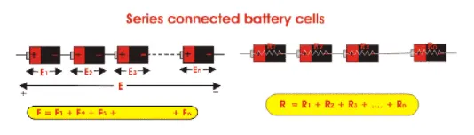
1. Series Batteries:
When in a battery, the positive terminal of one cell is connected with the negative terminal of the succeeding cell, then the cells are said to be connected in series. The overall emf of the battery is the algebraic sum of the emf of all individual cells connected in series.
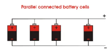
2. Parallel Batteries:
When positive terminals of all cells are connected together and similarly negative terminals of these cells are connected together in a battery, then the cells are said to be connected in parallel. The current delivered by the battery is the sum of currents delivered by individual cells.
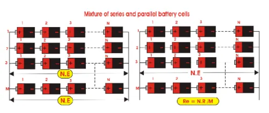
3. Mixed Grouping of batteries or series-parallel batteries:
The cells in a battery can also be connected in a mixture of both series and parallel. These combinations are referred to as the series-parallel battery. A load can require both voltage and current more than that of an individual battery cell. For achieving the required load voltage, the desired numbers of battery cells can be combined in series and for achieving the required load current, desired numbers of these series combinations are connected in parallel.
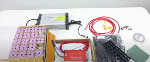
Components for the Battery Pack Assembly:
Required -
1. 2200 cells (as per calculations)
2. Nickel strips
3. PVC Heat sink film
4. Spot welder
5. Connectors
6. Cell holder
7. Solder
The following steps are used for assembling the battery pack.
Step - 1:
We are going to start with snapping square cell holders together. One can use cell terminal blocks, but they will consume more space than the hexagonal holders. Put the insulator gasket on the positive side of the cell.
The components of the battery pack are shown below.
The cell holder matrix is shown below.

The cell with an insulator gasket is shown below.

Step - 2:
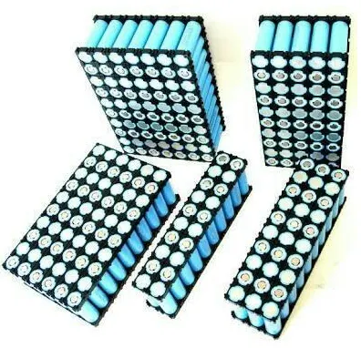
Place the cells in the cell holder matrix. After loading all the cells we will place the second cell connector block on the other side.
Step - 3:
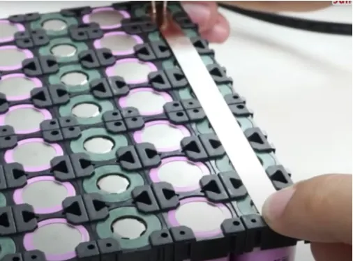
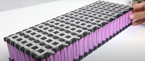
Connect the cells with nickel strips using the spot welding process. The series connection will be made by connecting the positive terminal of the cell to the negative terminal. The parallel connection will be made by connecting the same terminals. We will be welding the nickel strips to terminals of the cells which will be later used to attach a balancing wire.
The cell connection with the nickel strip using a spot welding tool is shown below.
The connection matrix including terminals for balancing wire is shown below.
Step - 4:
After the connections are made, stick a PVC heat sink film to the cell. We will then solder the balancing wire to the terminals and the battery management system's current supply wire to the battery pack.
The battery pack with the heat sink film is shown below.
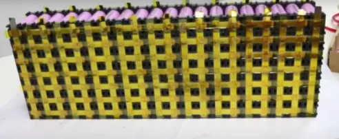
The image of soldering of balancing wire.

The battery pack assembled with the heat sink and the balancing wires is shown below.
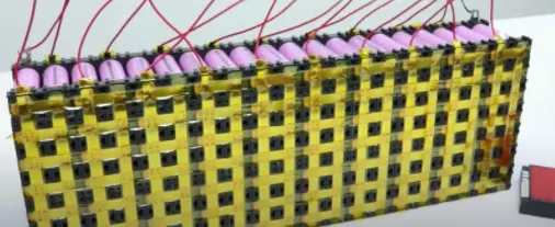
Step - 5:
Connect the balancing wire pin to the BMS and glue it to the side of the battery pack with BMS.
The soldering of supply wires is done as shown below.

The BMS will be attached to the battery pack as shown below.
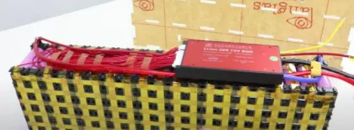
Step - 6:
Enclose the battery pack in the casing which is made up of plastic, metal or it can also be wrapped in a plastic sheet.
The battery pack in the casing is shown below.
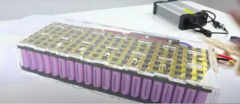
The battery pack after the assembly which is ready to use is shown below.
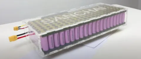
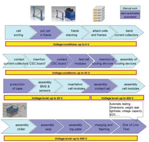
Overall view from starting to end of a mechanical battery pack assembly:
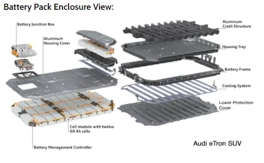
View of the Battery pack enclosure of Audi E-Tron:
We can see the exploded view of the battery pack of Audi etron in the below image.
CONCLUSION -
The design calculations for the battery pack with a total capacity of 18kWh are carried out and tabulated. The steps for the construction of the battery pack have also been discussed above.
REFERENCES -
3. https://x-engineer.org/category/automotive-engineering/vehicle/electric-vehicles/