Project 1 Mechanical design of battery pack
Aim: To prepare a detailed battery pack drawing along with its enclosure.
Solution:
The given information is -
1) Battery pack energy must be 18 kWh and
2) The cell used is: ANR26650M1-B
So, the detailed specification of the cell would be, Manufacturer of this Li-Ion cell ANR26650M1-B is LithiumWerks.
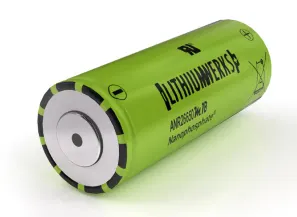
ANR26650M1-B is a 3.3 Volt, 2.5Ah Lithium Iron Phosphate (LiFePO4) Battery.
Lithium Werks’ 26650 cells are best for Power, Safety, and Life applications. They deliver very high power due to their use of patented Nano phosphate battery technology. Based on lithium iron phosphate chemistry (LiFePO4), the cells are inherently safe over a wide range of temperatures and conditions. Whether the application requires outstanding cycle life or stable float reliability, the Lithium Werks’ 26650 cells are suitable for a wide variety of power, pulse, or standby applications.
Nanophosphate Technology 26650 Lithium-Ion Power Cell Nanophosphate battery technology offers thermal-stable chemistry, faster charging, consistent output, low-capacity loss over time, and superior total cost of ownership (TCO). It provides the foundation for safe systems while meeting the most demanding customer requirements. Multiple layers of protection are
employed at the chemistry, cell and system levels to achieve an energy storage solution with superior safety and abuse tolerance compared to metal oxide lithium-ion chemistries.
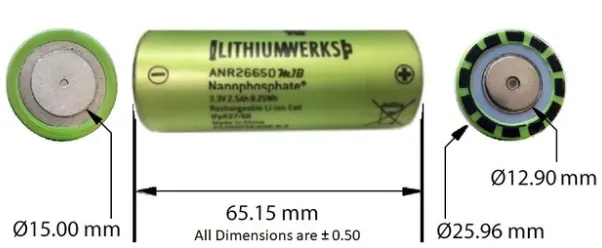
Dimensions
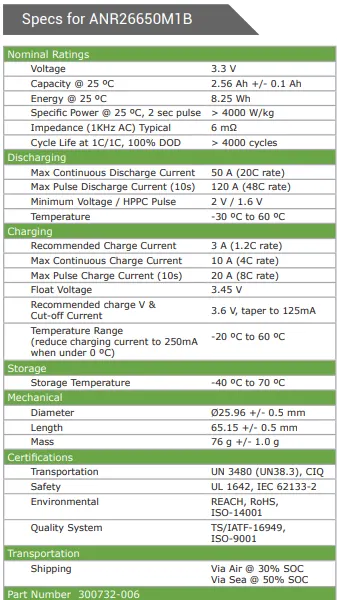
Specification
Features
The ANR26650M1-B is the next generation of A123 Systems’ pioneering 26650 cylindrical cells, now with greater power and energy density and lower impedance. This versatile lithium-ion cell is suitable for a wide variety of applications and system designs. Proven performance in the toughest conditions, combining durability, reliability, and safety, the ANR26650 cell offers an excellent combination of price performance.
Cylindrical Cell Primary Applications
- Portable high-power devices
- Stationary battery backup systems
- Grid stabilization energy storage systems
- Commercial truck and bus hybrid electric vehicles (HEVs)
Nanophosphate LiFePO4 Benefits
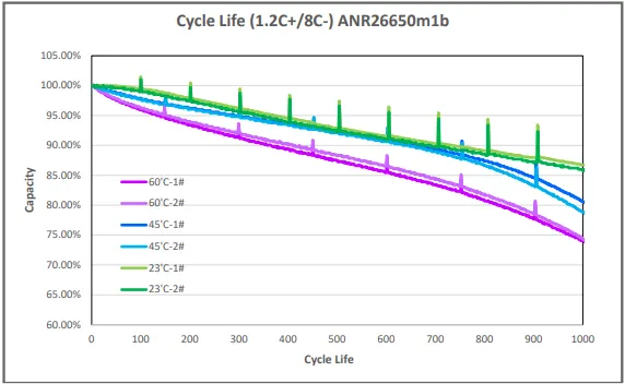
- Cycle Life at 1C/1C, 100% DOD, > 4000 cycles
- Safety: Excellent abuse tolerance and environmentally friendly
- Life: Excellent calendar life, 10X cycle life vs. conventional lithium-ion
Applications of ANR26650M1-B cells:
• Energy storage
• Frequency regulation
• Uninterruptible Power Supplies
• Communication technologies
• Aviation/Aerospace
• Electrified mobility devices
• Industrial equipment
• Medical devices
• Consumer Products
Discharge voltage profile of the cell with respect to different operating temperatures and the life cycle graph as per the data sheet provided by Lithiumwerks.
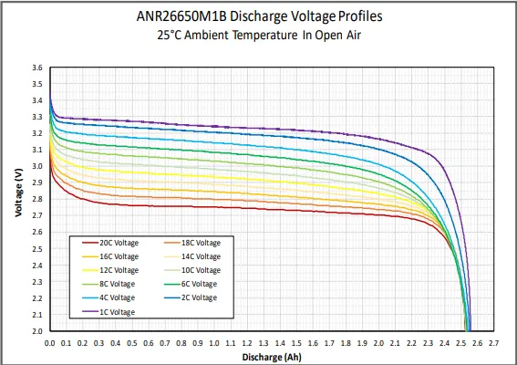
Important parameters for the assumption and designing of a battery pack- ANR26650M1-B
| Manufacturer: | LithiumWerks |
| Mfg. PN: | 300732-006 |
| Chemistry: | Lithium Iron Phosphate (LiFePO4) |
| Voltage: | 3.3 Volts |
| Capacity @ 25°C: | 2.56 Ah |
| Energy @ 25°C: | 8.25 Wh |
| Energy @ 25°C: | 8.25 Wh |
| Specific Power: | >4000W/kg | (@ 25°C, 2 sec pulse) |
| Impedance: | >6mΩ | (1kHz AC) Typical) |
| Cycle Life: | > 4000 Cycles | (@ 1C/1C, 100% DOD) |
Let's design a battery pack now,
Assumptions:
Given - Battery Pack Energy = 18 kWh
We will compare the overall voltage capacity with any existing EV in the market. Suppose for KIA EV6, the overall voltage is 400 V and 800 V, let us choose 400 V for the EV Battery Pack (Voltage required to run the motor as well as all the auxiliary accessories inside the vehicle).
Overall Voltage = 400 V
As we all know, the voltage can be increased by connecting cells in series and the current can be increased by connecting the cells in parallel. As per our requirement, we would be requiring a voltage of 400V so the battery modules should be designed in such a way that the output voltage must match the overall voltage requirement.
In simpler words, if we connect cells in series we will be adding or increasing the voltage of the pack without affecting the capacity or the current present in the cell, as the current in a series connection remains constant.
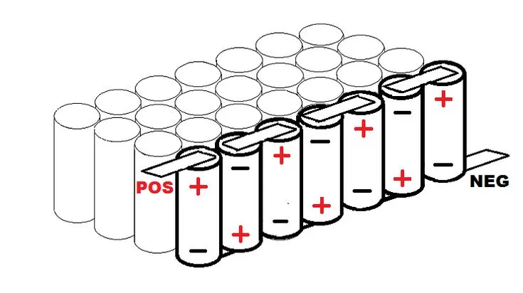
And if we connect cells in parallel, we will be adding or increasing the current of the pack without affecting the voltage of the individual cell, as the voltage in a parallel connection remains constant.
As per the given data sheet of cell, ANR26650M1-B,

For instance, we can calculate the number of cells we need to build a battery pack,
The energy required by a battery pack (given) = 18 kWh = 18 * 1000 Wh
= The energy required by a battery pack (given) / individual cell energy
= 18000 / 8.25
= 2181.88
= 2182 cells (Approximately)
Approximately 2182 cells would be required to design a battery pack for a given energy.
Voltage = 3.3 V and Capacity = 2.56 Ah
Individual cell voltage is 3.3 V and we have the requirement of 400 V for an entire battery pack, so connecting cells in series combination until we reach a total of nearly 400 V of voltage.
Therefore, Number of cells require = 400 V / 3.3 V = 122 cells
We need to connect 122 cells in series in order to match the overall voltage.
Individual Cell energy = 8.25 Wh
If we consider that there are only 122 cells in a single module which are connected in series combination,
The energy produced from a single module = 1 Module size * Energy of a single cell
= 122 * 8.25
= 1006.5 Wh
Also, the required energy of the battery pack is given to us in the question itself and we know the energy produced by a single module, So,
So, 18 kWh = 18 * 1000 Wh (1000 for converting kWh into Wh) = 18000 Wh / 1006.5 Wh
= 17.88
= 18 modules (Since module numbers cannot be in decimals)
We need 18 such modules connected in Parallel to meet the energy requirements for this project.
So, Battery Model becomes 122 series and 18 parallel. Hence, 122S18P configuration.
Total Cells in a battery pack = 122 * 18 = 2196 cells.
We considered 2182 cells (at the beginning of our calculation) as the approximate cell requirement and we got 2196 cells as total cells.
As the number of cells, we calculated is greater than the assumed cells, the energy produced by the total number of cells would be also greater than the assumed cell's energy produced.
= 2196 * 8.25 = 18117 Wh (Which is greater than the energy produced by 2182 cells {18000 Wh})
Capacity is given as 2.56 Ah (In the datasheet)
Since the cells connected in series won't participate in increasing and decreasing of battery pack capacity as current remains constant in series connection. Only cells connected in parallel would participate in capacity alterations,
Overall capacity (Ah) = 2.5 Ah * 18 modules
= 45 Ah
45 Ah means it will take 1 hour to fully discharge 45 Amperes of current present in the battery (Considering the 1C Rate).
2C rate = 90 A * 30 mins
1C rate = 45 A * 1 h
0.5C rate = 24.5 A * 2 h
Fitting the model of the battery pack (122S18P) inside the frame of the vehicle,
In order to decide how much of the space, the battery pack model would consume inside the vehicle's frame, we calculate the volume of the battery pack model,
Volume calculation:
Given, cell diameter = 26mm
Assuming, the margin at both sides of the cell = 4mm
Length of casing = Number of cells in series * (cell diameter + margin at both sides of cell) + clearance at the side (diameter of edged cell + margin)
`= 122** (24+6) + (2**(24+6))`
`= 122** (24+6) + 60`
`= 3720 mm`
The breadth of casing = Number of cells in parallel * (cell diameter + margin at both sides of cell + clearance at the side (diameter of edged cell + margin)
`= 18**(24+6) + (2**(24+6))`
`= 18**(24+6) + 60`
`= 600 m`
Height of casing = 65mm + 35mm (Height of cell + margin for wiring, Cell holders and metal strips)
= 100 mm
Volume = Length * Height * Breadth = 3720 * 600 * 100 = 223200000 / 10^9 = 0.2232 m^3
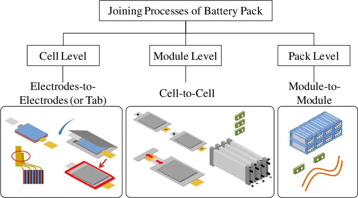
The Assembling Process of a battery pack includes electrodes-to-tab level assembly, the casing (sealing) of the electrodes and electrolyte, cell-level assembly, and module-to-module level assembly.
Joining Techniques -
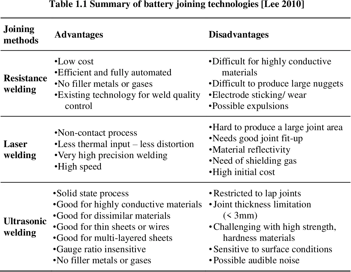
- Ultrasonic Metal Welding (UMW) -
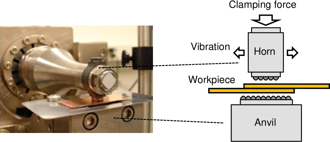
Ultrasonic welding is an industrial process whereby high-frequency ultrasonic acoustic vibrations are locally applied to work pieces being held together under pressure to create a solid-state weld. It is commonly used for plastics and metals, and especially for joining dissimilar materials. In ultrasonic welding, there are no connective bolts, nails, soldering materials, or adhesives necessary to bind the materials together. When used to join metals, the temperature stays well below the melting point of the involved materials, preventing any unwanted properties which may arise from high-temperature exposure of the metal. - Resistance Spot Welding -
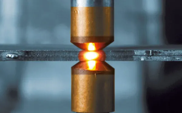
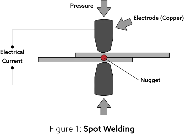
Spot welding or resistance spot welding is a type of electric resistance welding used to weld various sheet metal products, through a process in which contacting metal surface points are joined by the heat obtained from resistance to electric current.
The process uses two shaped copper alloy electrodes to concentrate welding current into a small "spot" and to simultaneously clamp the sheets together. Workpieces are held together under pressure exerted by electrodes. Typically, the sheets are in the 0.5 to 3 mm (0.020 to 0.118 in) thickness range. Forcing a large current through the spot will melt the metal and form the weld. The attractive feature of spot welding is that a large amount of energy can be delivered to the spot in a very short time (approximately 10–100 milliseconds). This permits the welding to occur without excessive heating of the remainder of the sheet.
- Laser Beam Welding -
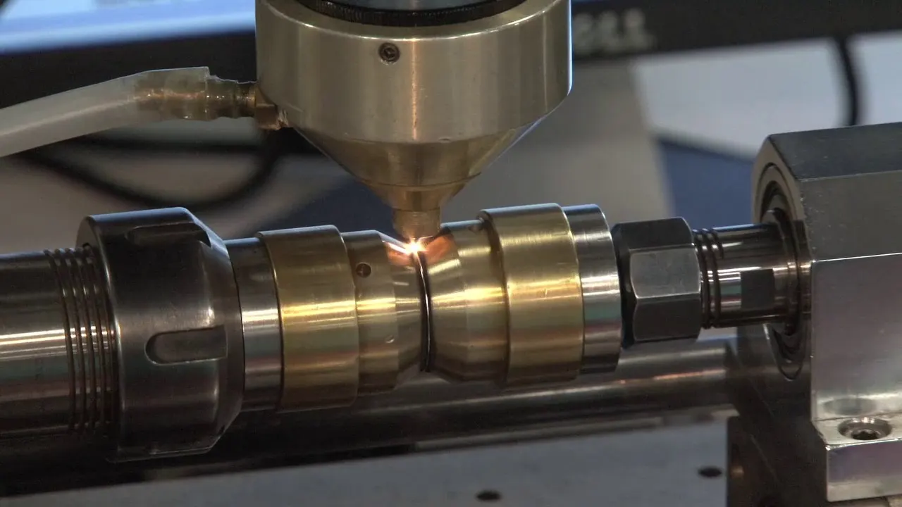
Laser beam welding (LBW) is a welding technique used to join pieces of metal or thermoplastics through the use of a laser. The beam provides a concentrated heat source, allowing for narrow, deep welds and high welding rates. The process is frequently used in high volume and precision requiring applications using automation, as in the automotive and aeronautics industries. It is based on keyhole or penetration mode welding.
BATTERY ENCLOSURES:
Thermal Runaway - When the internal chemistry of the cell becomes unstable due to physical damage, over-heating or over-charging, the cell starts generating heat from the chemical reactions that are not desirable reactions. This leads to more heat and more unfavourable reactions all the way till a cell goes into thermal runaway. When this heat spreads from one cell to an adjacent cell, it is called runaway propagation.
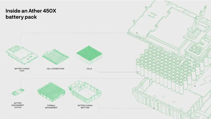
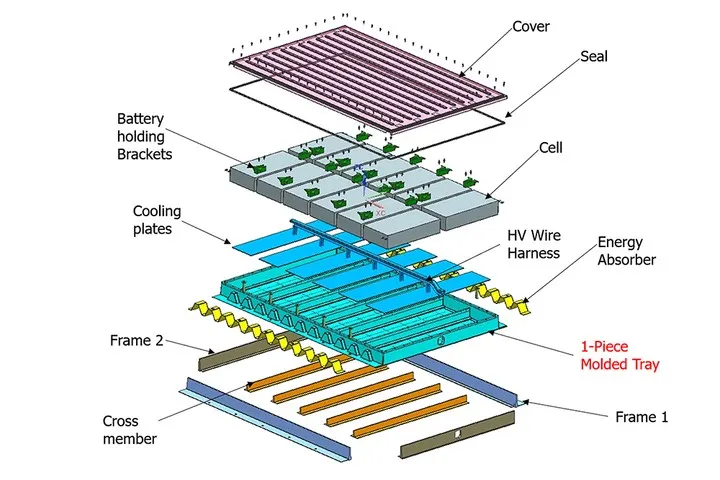
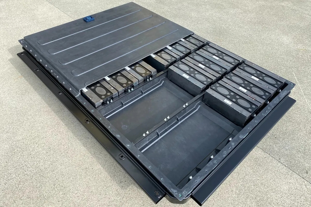
Design, packaging and structural integrity:
The next step in a safe battery pack design is the packaging and structural integrity. The spacing between cells and the choice of materials are important to ensure that:
-
If there’s a defect in one cell, the enclosure has to prevent thermal runaway propagation to other cells in the battery pack.
-
The structures to hold cells in place have to withstand vibration/shocks from daily usage, as well as some rare scenarios like drops or crashes.
-
The pack has to withstand Indian roads and seasons for at least a decade of use and any additional Ingress Protection (IP) ratings.
Cell Holders/ Assemblers:
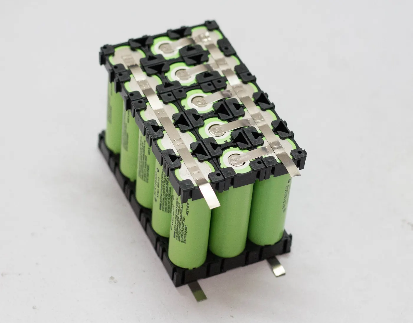
The primary function of a battery holder is to keep cells fixed in place safely and securely while conveying power from the batteries to the device in question. External connections on battery holders are most often made by contacts either with pins, surface mount feet, soldered lugs or via a set of wire leads.
Battery holders are often designed to be incorporated within the body of an electrical item, but they’re also frequently sold as external compartments or attachments. Either way, some of the most important factors to consider when choosing an appropriate battery holder for a given application will be:
- Battery size
- Compatible cell types
- Contact/terminal style
- Battery mounting and insertion method
- Unit size and shape
- Battery holder cover and housing design
- Build quality and manufacturer reputation
Lego casing-
Battery Types: Characterized by Shape,
Bibliography-
5) UMW