Project 1 Mechanical design of battery pack
AIM
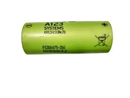
Create a detailed battery pack with the following specifications: Cell: ANR26650M1-B, drawing, enclosure, and battery pack capacity: 18kWh. List the underlying premise.
ABSTRACT
In this Project, we'll figure out all the numbers needed to construct an EV battery pack. For our battery pack, we're going to use Cell: ANR26650M1-B. All electrical factors, including temperature, Depth of Discharge, Operation Current, Energy Density, Work Cycles, Battery Capacity, State of Charge (SOC), State of Health (SOH), and Ampere-Hour (Ah) Capacity, will be taken into account when determining parameters. Additionally, we compute every geometrical factor, including size, weight, volume, area, etc. Finally, we take into consideration a few different battery pack container models.
OBJECTIVE
1) Data collection from the Nanophosphate High Power Lithium-Ion Cell PDF for Cell: ANR26650M1-B.
2) Performing a complete electrical analysis on an 18 kWh battery pack.
3) Calculating the battery pack's physical size.
4) Take into account the ideal container for the Battery Pack's measurements that we computed.
METHODOLOGY
1) To construct the battery pack for any electric vehicle, we must first determine the ratio of power to motor power, and then, based on that, we must model the battery pack to determine the required amount of power, which is 18kWh.
2) We must figure out how many cells are in series and parallel for the 18kWh battery pack.
3) The correct geometry and topology consideration for manufacturing batteries must be calculated after the series and parallel combination calculations.
4) After assembly, the battery pack needs to be properly enclosed to protect it from thermal damage and other physical harm.
THEORY
One of a battery electric vehicle's most crucial parts is the high voltage battery (BEV). Other parts and characteristics of the car are significantly impacted by the battery specifications, such as:
- maximum traction motor torque
- maximum regeneration brake torque
- vehicle range
- vehicle total weight
- vehicle price
The specifications of the high voltage battery determine pretty much all of the key features of a pure electric vehicle (EV).
We're going to start with 4 fundamental input parameters for the construction of our electric vehicle batteries.
- chemistry
- voltage
- average energy consumption of the vehicle on a driving cycle
- vehicle range
During discharging, a battery's electrochemical cells (also known as battery cells) transform chemical energy into electrical energy and electrical energy back into chemical energy (during charging). The chemistry of a battery is determined by the kind of components it contains and the chemical processes that take place during charging and discharging cycles.
Electrodes (anode and cathode), separators, terminals, electrolytes, and a container or enclosure are the five main parts of a battery cell. There are various types of cells used in automotive applications. A battery module is a collection of individual battery cells that functions as a single mechanical and electrical unit. A battery pack is created by electrically connecting the modules.
FIG: CYLINDRICAL AND PRISMATIC CELLS
The highest continuous electrical power that may be produced depends on the battery voltage level. Voltage U [V] and current I [A] are multiplied to produce power P [W]:
P = U* I
The high voltage wires' diameter increases with increasing current, and so do thermal losses. For this reason, a maximum current limit should be used, and a greater voltage should be used to achieve the nominal power. We're intending to use a 400 V nominal voltage for our application.
The high voltage battery must provide the energy for the vehicle's Eaux [Wh/km] auxiliary equipment, such as the 12 V electrical system, heating, cooling, etc. The effectiveness of the powertrain p [-] in converting electrical energy to mechanical energy must also be taken into account.
BATTERY ARCHITECTURE
Battery cells are organised in strings and modules to form the basis of all high voltage battery packs. A battery cell can be thought of as the voltage's smallest division.
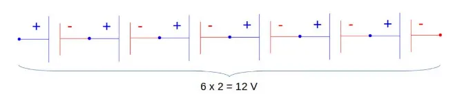
Modules made up of individual battery cells can be arranged in parallel or series. Additionally, battery modules can be linked in series or parallel to form a battery pack. There may be different levels of flexibility depending on the battery's specifications.
The quantity of series-connected cells determines the voltage of the entire battery pack. For instance, the sum of the individual voltages of six cells connected in series will equal the total (string) voltage of those cells.
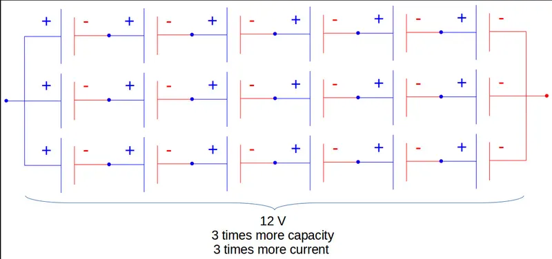
In order to increase the current capability the battery capacity, more strings have to be connected in parallel. For example, 3 strings connected in parallel will triple the capacity and current capability of the battery pack.
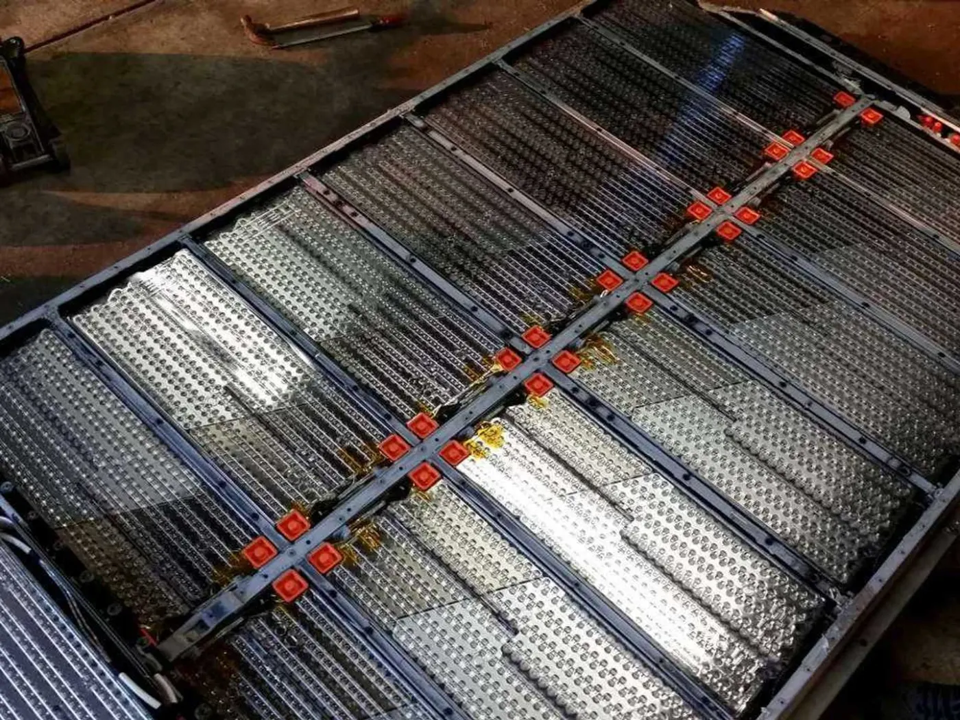
An example is the high voltage battery pack of Tesla Model S, which has:
- 74 cells in a parallel-group
- 6 groups in series for a module
- 16 modules in series
- 7104 cells in total
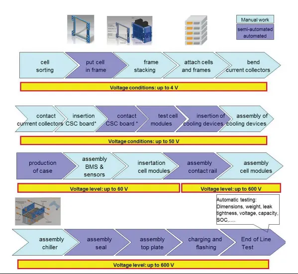
BATTERY PACK PRODUCTION LINE
PROCEDURE
1) The cell computation must come first.
2) After that, battery pack assumptions will be made.
3) After making assumptions, we must calculate the battery pack.
4) Using Cell Dimensions, we determine how much surface area a battery pack needs.
5) Based on the equations above, we manufacture battery packs.
Following are the all cell (Cell: ANR26650M1-B) parameters for battery pack
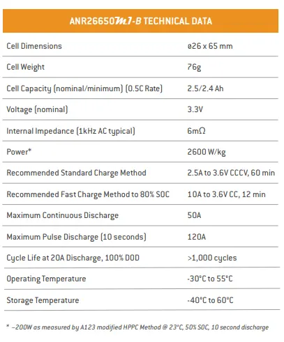
We will calculate additional parameters from the ones mentioned above that are used in the building of battery packs.
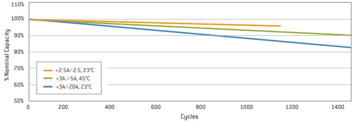
Cycle Life Performance at 100% DOD, Different Cell Discharge Rates, and Temperatures.
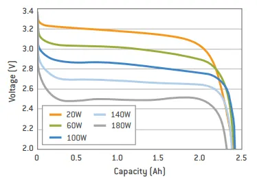
Constant Power Discharge Characteristics at 23°C of cell:
2.5C Constant Current Discharge at Various Temperatures:
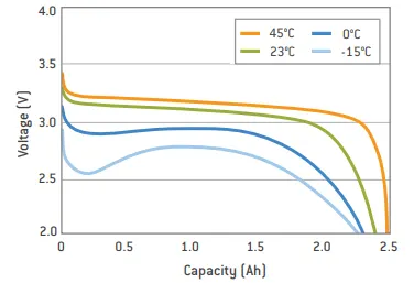
Great-performance LiFePO4 (nanophosphate lithium iron phosphate) battery technology from A123 provides high power and energy density along with superior safety performance and lengthy life cycles in a less weight, more compact container. Our cells' low capacity loss and impedance development over time, together with their high usable energy throughout a broad state of charge (SOC) range, enable our systems to satisfy end-of-life power and energy demands with a minimum amount of pack oversizing.
CELL DIMENSIONS
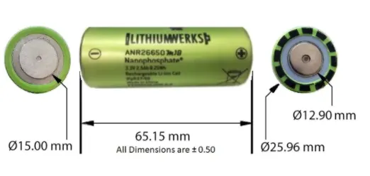
1. VOLUME OF CELL.
We know that the equation to find the volume of cylinder is given by
V=pi*r^2*h
From Datasheet of Cell, we have 'r' and 'h' values
r=0.013m and h=0.065m.
we have V=pi*r^2*h
substituting we get
V=3.14*0.013^2*0.065
V=0.0000344929m^3
The volume of the cell is 0.0000344929m^3
2. CELL ENERGY
The volume of battery pack can be found out now.
Cell Energy= Cell Capacity (Ah) × Cell Voltage (V)
= 2.5 × 3.3
= 8.25 Wh
Cell Energy is 8.25 Wh.
3. VOLUMETRIC ENERGY
The value of a single cell is used to calculate the total energy of the battery pack.
Single Cell Energy Density
Volumetric energy (Wh/m3) = Single Cell Energy / Volume of each cell
= 8.25 Wh / 0.0000344929m3
=2,39,179.6572 Wh/m3
Single Cell Energy Density is 2,39,179.6572 Wh/m3
BATTERY PACK ASSUMPTIONS
There are 50 cell are in series and 44 cells are in parallel, and as above maintioned we are going to use Cell: ANR26650M1-B this cells.
BATTERY PACK CALCULATIONS
Total no of cells=Series cells * parallel cells
=50*44
=2200.
Total no of cells required are 2200.
We can therefore compute the battery pack's voltage and current using a series and parallel combination.
Voltage= no of cell in series* nominal voltage.
= 50*3.3
= 165V
The total value of voltage is 165V.
Current=No of parallel cells * cell capacity
= 44*2.5
=110Ah.
The total value of Current is 110Ah.
Now that we know how much energy this combination has based on the product of its voltage and current, we can determine if it will satisfy our requirements or not.
Energy= Voltage * Current
= 165 * 110
= 18150WAh.
The total value of Energy is 18150WAh.
Therefore, our calculations meet the criteria that we set.
Now that we have the total number of cells and the volume of each cell, we can determine the total volume needed for the battery pack.
Total volume = no of cells * Volume of single cell
= 2200 * 0.0000344929
=0.07588438m^3
Total volume required for battery pack is 0.07588438m^3
Additionally, we have the weight of a single cell, from which we may determine the overall weight of a battery pack devoid of other mechanical and electrical connections.
Weight = No of cells * weight of single cell.
= 2200 * 0.076
= 167.2kg
Weight of battery pack is 167.2kg
Energy Density=volume * battery pack energy
= 0.07588438 * 18150
=1,377.301497kWh/m^3
Energy density=1,377.301497kWh/m^3
We currently have all the necessary parameters to physically create the battery pack.
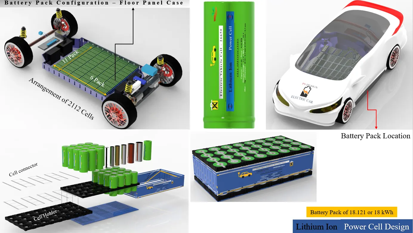
The arrangement design of single-cell is shown below:
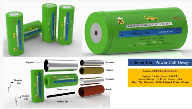
hen,
2112 cells will have 50S / 44P
Here I arrange the pack such that it will build a proper battery pack.
The detail technical specification of 2112 battery pack is as follow:
- Package: 50S / 44P
- Capacity: 110 Ah
- Voltage: 165 V
- Weight: 167.2kg (Only Cells)
- No of Cells: 2100
- Power: 18150Wh or 18.15 kWh
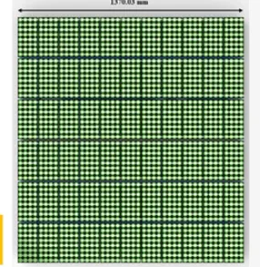
Here I also set up the battery pack in the lower floor panel case of an electric car; a basic diagram of the battery pack in an electric car is given below:
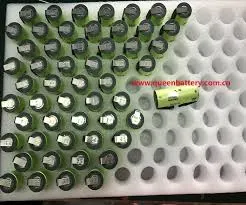
CELL HOLDER
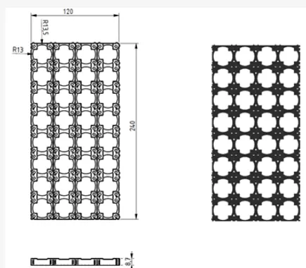
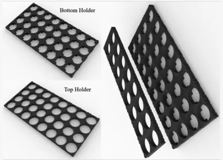
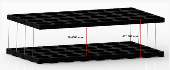
The primary purpose of a battery holder is to maintain cells fastened in place safely and securely. It is also used to maintain cells in a good arrangement to reduce mechanical vibration and improve the thermal runway between the gaps between the cells. Polypropylene or nylon bodies rated for 80-100 °C make up the majority of the cell holder's body.
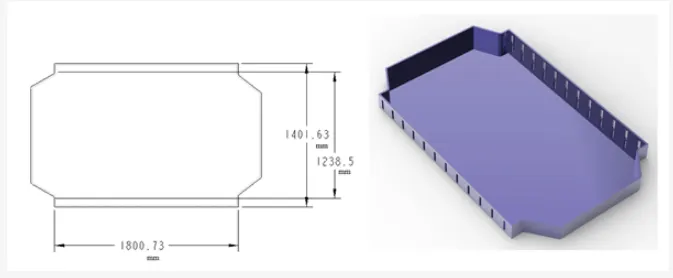
DESIGN OF PACK COVER
In order to make the battery pack lightweight, the pack cover is essentially made of aluminium. The design is as follows, and the casing/cover thickness is 0.5 mm:
Below the bottom battery holder, a bottom cover is seen.

DESIGN OF LOWERCASE FOR BATTERY PACK
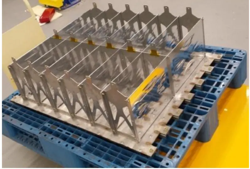
In essence, the lower case is a component installed in an electric car to complete the battery pack assembly. In order to protect the battery pack from environmental contamination and dust, a lower casing is also made of aluminium and includes top and bottom covers.
The lower case's appearance is displayed.
POSITIVE AND NEGATIVE CLIP
You must use nickel strips or strong wire to connect the several cells together to create the battery pack. Nickel strips are frequently used for this. There are generally two types of nickel strips on the market: pure nickel strips and nickel-plated steel strips. I'll advise getting pure nickel. Although slightly more expensive than nickel-plated steel, it has substantially less resistance. Low resistance results in less heat being produced during charging and discharging, extending the useful life of the battery.
Nickel strips are available in a variety of sizes and lengths.

JOINING OF CYLINDRICAL CELL BATTERY PACK
Although cylindrical cells have low packaging efficiency because to their round cross-section, they have enhanced thermal management efficiency due to their compact design. Here, I connect multiple cells using a positive and negative tab.
Following is an illustration of how joining techniques can be used to construct battery packs utilising cylindrical cells
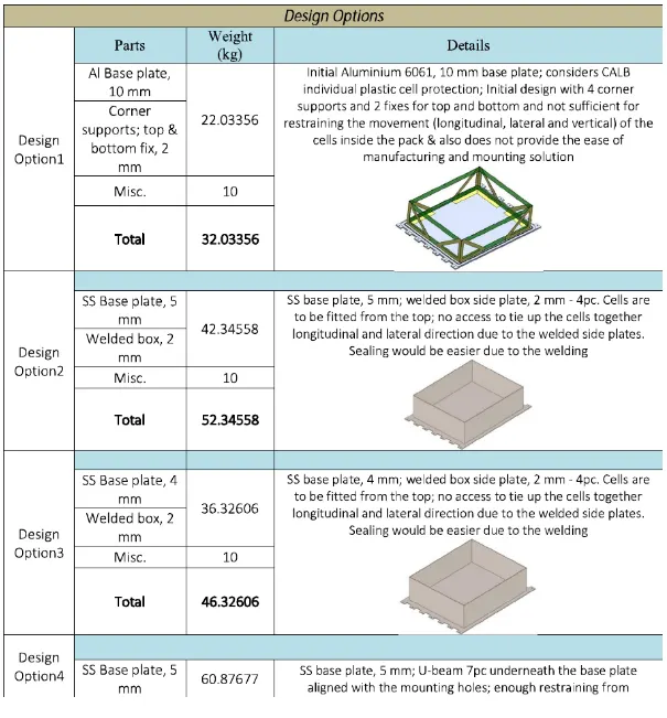
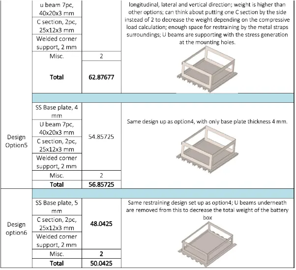
Some other design options for battery pack constructions
RESULTS
| NO | Calculated Parameters | Values |
| 1 |
Cell Volume |
0.0000344929m^2 |
| 2 | Cell Energy | 8.25Wh |
| 3 | Cell Density | 239179.6572kWh/m^2 |
| 4 | Pack assumptions | 50s 44p |
| 5 | Total no of cells | 2200 |
| 6 | Voltage | 165V |
| 7 | Capacity | 110Ah |
| 8 | Energy | 18150WAh |
| 9 | Total volume | 0.07588m^2 |
| 10 | Total Density | 1377.30kWh/m^2 |
| 11 | Weight | 167.2kg |
CONCLUSION
The drawing of Cell: ANR26650M1-B along with its specifications is done in this project. The detailed report of the calculations carried out is explained through the project. Also the drawing and the data sheet is also attached below.