Project 1 Mechanical design of battery pack
#12 - Project 1 Mechanical design of battery pack
- Battery pack capacity: 18 kWh
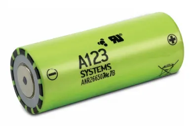
- Cell: ANR26650M1-B
- Prepare a detailed battery pack drawing along with its enclosure. State your assumptions.
- ABSTRACT:
- In this project, we are going to calculate the all parameters which are required for the build EV battery pack.
- We are going to use the Cell: ANR26650M1-B for our battery pack.
- In parameters, we will consider all electrical aspects like temperature, Depth of discharge, Operation current, Energy density, Work cycles, Battery capacity, State of Charge (SOC), State of Health (SOH), Ampere-hour (Ah) Capacity.
- We also calculate all geometrical considerations like size, weight, volume, area, etc. In the end, we consider some enclosures model for our battery pack.
- OBJECTIVE:
- Collecting the data of Cell: ANR26650M1-B from Nanophosphate High Power LithiumIon Cell PDF.
- Calculating all Electrical parameters for 18 kWh Battery Pack.
- Calculating all Physical dimensions for Battery Pack.
- Consider perfect enclosure for dimensions that we calculated for the Battery Pack.
- METHODOLOGY:
- To build the Battery pack for any Electric Vehicle, we have to calculate the first proportion of power then motor power, and depend on that we will model the battery pack so we know how much power we required which is 18kWh.
- For the 18kWh battery Pack we have to calculate how many cells are parallel and how many cells are in series.
- After calculation of series and parallel combination we have to calculate the proper Geometry and topology consideration for assembling batteries.
- After Assembly we need to find a proper enclosure for the battery pack for thermal consideration and other physical damages.
- MECHANICAL DESIGN PROCESS :
Required Energy Capacity for the pack = 18 kWh
Cell Datasheet
Followings are the all cell (Cell: ANR26650M1-B) parameters for battery pack:
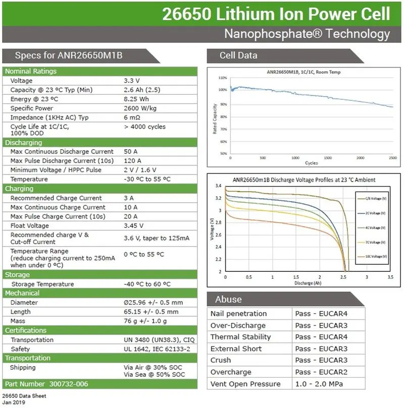
From above all parameters we will calculate further parameters which are used for battery pack construction.
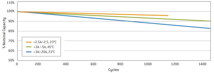
Cycle Life Performance, 100% DOD, Various Temperatures and Discharge Rates of cell:
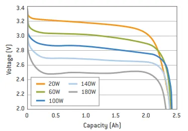
Constant Power Discharge Characteristics at 23°C of cell:
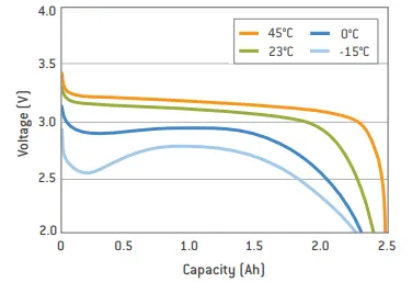
2.5C Constant Current Discharge at Various Temperatures:
A123’s high-performance Nanophosphate lithium iron phosphate (LiFePO4) battery technology delivers high power and energy density combined with excellent safety performance and extensive life cycling in a lighter weight, more compact package. Our cells have a low capacity loss and impedance growth over time as well as high usable energy over a wide state of charge (SOC) range, allowing our systems to meet end-of-life power and energy requirements with minimal pack oversizing.
EV design - Battery calculations.
Given data
Battery energy = 18 kWh
From the ANR26650M1-B data sheet
Nominal voltage = 3.3 V
Cell capacity = 2.5 Ah
Internal impedance = 6 mΩ
Cell weight = 76 g
Cell Dimensions = 26*65 mm
Operating temperature = -30°C to 55°C
Number of cells (N) = energy / (nominal voltage*capacity)
N = 18000 / (3.3*2.5)
N = 2182 cells nearly
We need minimum of 2182 cells to get 18 kWh energy, now based on that, we need to decide configuration – series and parallel but it not exact cells.
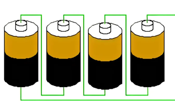
In series configuration capacity remains the same and voltage will be the sum of individual cell voltage.
In a parallel configuration, the voltage remains the same and capacity accumulates.
And we assumed 300 Volts are need to run the vehicle.
The capacity of the total battery for 18kWh is,
Capacity = 18000/300
Battery capacity = 60 Ah
The nominal voltage of one cell is 3.3V.
Number of series cells required to produce 300 V (Ns) = voltage required / nominal voltage of one cell
Ns = 300/3.3
Ns = 90.9
Ns = 91 cells in series
So, to produce 300 V of voltage we require 91 cells of ANR26650M1-B in series which having 3.3V. the excess of voltage be consider in losses.
The capacity of the whole module will be 2.5
To find the number of cells which will be connected in a parallel configuration
Np = 60 / 2.5
Np = 24
Np = 24 cells in parallel
Here we use 24 cells are in parallel to run the battery with 60 Ah capacity.
The total cell model is having the pack of 91S24P configuration
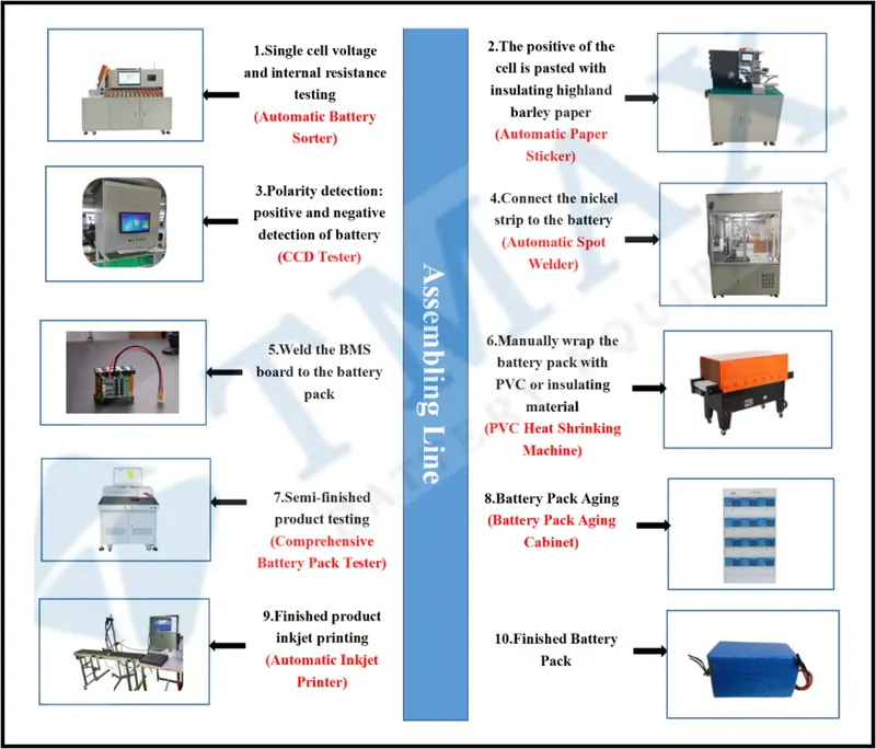
- The spot-welding machine has anintelligent welding function which can improve the efficiency of the battery pack during the welding process. It’s equipped with built-in temperature sensors and an intelligent cooling system which can automatically work according to machine’s internal temperature. It is used to weld the strips which is used to connect the cells for series a parallel.
Battery module:
The total battery power = (91*3.3 V) * (24*2.5 Ah)
= 18018 Wh
= 18.018 kWh
The battery requirement is 18.018 kWh battery pack, the required configuration of that pack is 91S24P, i.e., 91 series, and 24 cells connected in parallel
To build such a large grid, we need to slip the battery packs into the battery module, which reduce the complexity of monitoring and optimising battery management and minimizing battery damage.
For that we use the modules which take care of cells protection, monitoring, connections of set of the cells.
In this we are dividing the set of cells from battery pack 91S24P into 7S4P
So, the no of cells in each module are = 7*4
= 28 cells
Total no of cells = 2184 cells
Therefore, no of modules = 2184 / 28
= 78 modules
We have already calculated battery capacity which is 60 Ah means it is going to supply 60 A current per hour. which can be considered as C-rate of the battery.
Let us assume the energy consumption for 1 km is 100 Wh. So, the total range of the battery for 18kWh is 180 Km.
There fore the no of kilometres that a vehicle run with full charge of 18kWh is 180Km.
Battery enclosure pack size:
ANR26650 cell has 26mm diameter and 65mm height. On the basis of that we need to decide battery size of battery casing which is total battery pack.
Length of casing (L) = number of cells at series*(cell diameter (26) + margin at both side of the cell which to free up space called holders and gaps for the sheet protectors etc (4) + clearance at side (diameter of edged cell + margin) (All should be in value with mm)
L = 91*30+80
L = 2810 mm
- Cells in series
 Cell holders,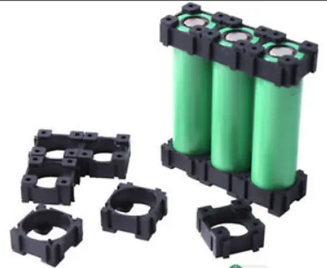
Breadth of casing (B) = number of cells at parallel*(cell diameter (26) + margin at both side of the cell (4) + clearance at side (diameter of edged cell + margin) for protection
B = 24*30 + 80
B = 800 mm
- Cells in parallel,
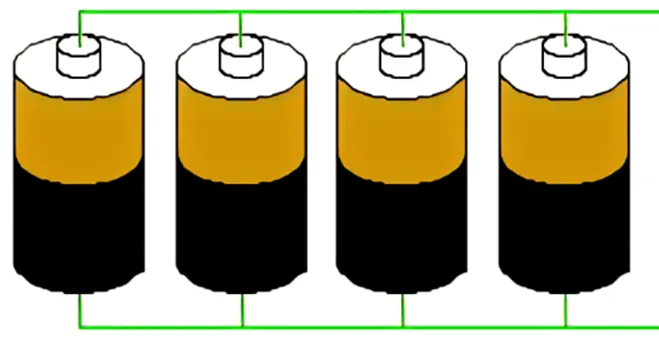 Side clearances,
There fore the total area of the battery is = 2810 * 800
= 224800 mm
= 2.248 m
Height of the battery (H) = 65 (height of the cell) + 35 (wires, holders, strips etc)
= 100 mm
Therefore, the volume of the battery is = L*B*H
= 2810*800*100
= 0.224 m
Weight of battery pack
Cell weight = 76g from data sheet
Number of cells = 2184
Battery pack weight (W) = cell weight*number of cells + weight of accessories
W = 76*2184 + 4.5 = 165.984 + 4.5 = 170.48kg.
- THEORY:
The high voltage battery is one of the most important components of a battery electric vehicle (BEV). The battery parameters have a significant influence on other components and attributes of the vehicle, like:
- Maximum traction motor torque
- Maximum regeneration brake torque
- Vehicle range
- Vehicle total weight
- Vehicle price
Pretty much all major aspects of a pure electric vehicle (EV) depend on the parameters of the high voltage battery.
For our electric vehicle battery design we are going to start from 4 core input parameters:
- Chemistry
- Voltage
- Average energy consumption of the vehicle on a driving cycle
- Vehicle range
A battery consists of one or more electrochemical cells (battery cells) which are converting chemical energy into electrical energy (during discharging) and electrical energy into chemical energy (during charging). The type of elements contained within a battery and the chemical reactions during discharging-charging events define the chemistry of a battery.
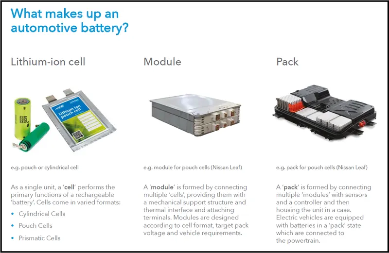
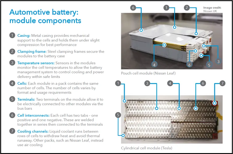
A battery cell consists of five major components: electrodes – anode and cathode, separators, terminals, electrolytes, and a case or enclosure. For automotive applications, there are different types of cells used Individual battery cells are grouped into a single mechanical and electrical unit called a battery module. The modules are electrically connected to form a battery pack.
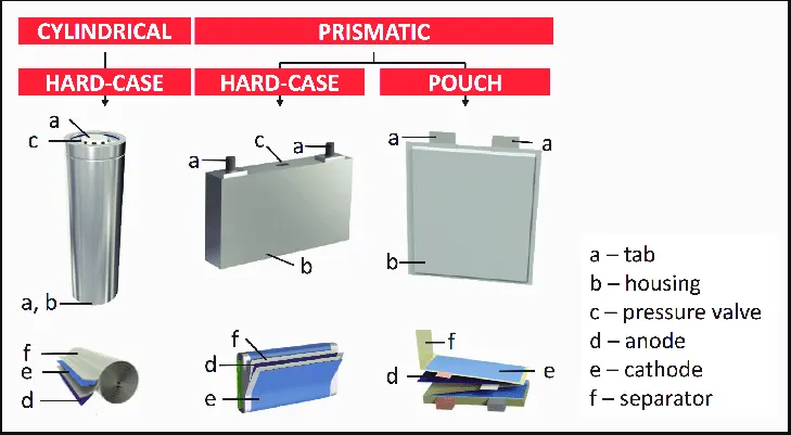
The voltage level of the battery determines the maximum electrical power which can be delivered continuously. Power P [W] is the product between voltage U [V] and current I [A]:
P = U* I
The higher the current, the bigger the diameter of the high voltage wires and the higher the thermal losses. For this reason, the current should be limited to a maximum, and the nominal power obtained by having a higher voltage. For our application, we are going to consider a nominal voltage of 400 V.
the energy needed for propulsion, the high voltage battery must supply the energy for the vehicle’s auxiliary devices Eaux [Wh/km], like 12 V electrical system, heating, cooling, etc. Also, we have to consider the efficiency of the powertrain ηp [-] during the conversion from electrical energy to mechanical energy.
Battery pack architecture:
All high voltage battery packs are made up from battery cells arranged in strings and modules. A battery cell can be regarded as the smallest division of the voltage.
Individual battery cells may be grouped in parallel and/or series as modules. Further, battery modules can be connected in parallel and/or series to create a battery pack. Depending on the battery parameters, there may be several levels of modularity.
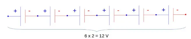
The total battery pack voltage is determined by the number of cells in series. For example, the total (string) voltage of 6 cells connected in series will be the sum of their individual voltage.
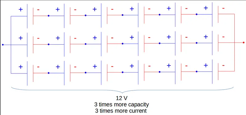
In order to increase the current capability the battery capacity, more strings have to be connected in parallel. For example, 3 strings connected in parallel will triple the capacity and current capability of the battery pack.
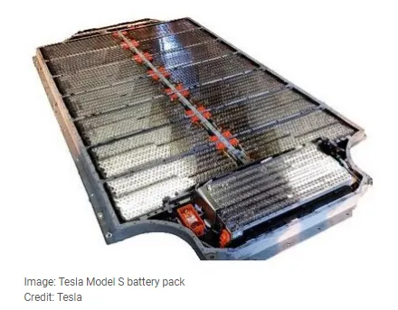
An example is the high voltage battery pack of Tesla Model S, which has:
- 74 cells in a parallel-group
- 6 groups in series for a module
- 16 modules in series
- 7104 cells in total
Stages of Battery Pack Design
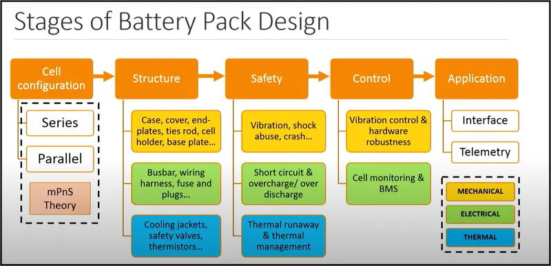
The various design elements to be considered while developing a battery pack are as follows :
1. Electrical Design
- Determination of capacity, voltage and current.
- High voltage isolation.
- Short circuit prevention.
- Efficient power delivery.
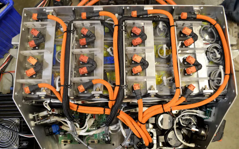
2. Thermal Design
- Improve pack efficiency.
- Mitigate thermal accidents.
- Increase pack life.
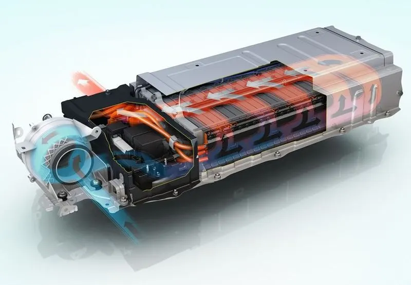
3. Mechanical Design
- Safe structure for extreme conditions.
- Cost, productivity and reliability.
- Ease of assembly and service.
- Aesthetics, compactness and light weight.
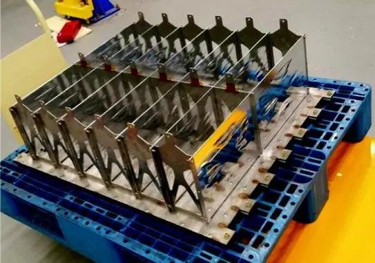
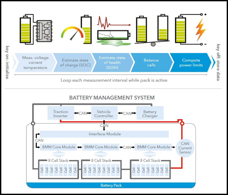
4. Battery Management System (BMS) Design
- Maintain cell / pack operating limits.
- Prevent events compromising safety.
- Control thermal systems.
- Communication and logistics.
Battery Pack Construction
1. Capacity and Voltage Requirements
High battery voltages are achieved by adding more cells in a series chain. The voltage of the battery is the voltage of a single cell multiplied by the number of cells in the chain. This does not increase the AmpHour capacity of the battery , but it increases the WattHour capacity, or the total stored energy, in proportion to the number of cells in the chain.Battery capacity can increased through adding more parallel cells. This increases the AmpHour capacity as well as the WattHour capacity without increasing the battery voltage. For batteries with parallel chains the capacity of the battery is the capacity of the individual chain multiplied by the number of parallel chains.Whereas cell voltage is fixed by the cell chemistry, cell capacity depends on the surface area of the electrodes and the volume of the electrolyte, - that is, the physical size of the cell. If at all possible the number of cells in a pack should be minimised to simplify the design and to minimise potential reliability problems. Fewer cells require fewer support electronics. Thus parallel chains should be avoided by specifying the highest capacity cells available.Cells with different capacities or cell chemistries should not be mixed in a single battery pack.
2. Cell Configuration
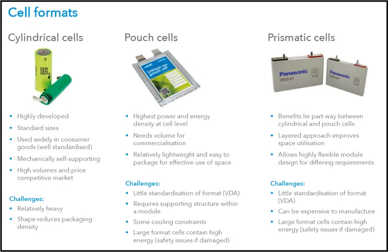
The ultimate shape and dimensions of the battery pack are mostly governed by the cavity which is planned to house it within the intended application. This in turn dictates the possible cell sizes and layouts which can be used. Prismatic provide the best space utilisation, however cylindrical cells provide simpler cooling options for high power batteries. The use of pouch cells provides the product designer more freedom in specifying the shape of the battery cavity permitting very compact designs. The orientation of the cells is designed to minimise the interconnections between the cells.
3. Battery Electronics
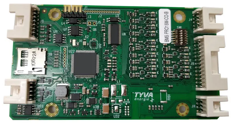
Besides the cells many battery packs now incorporate associated electronic circuits. These may be protection devices and circuits, monitoring circuits, charge controllers, fuel gauges, and indicator lights. Electronics for high power multi-cell packs also include cell balancing and communications functions. The packs may also be designed to deliver more than one voltage from the basic cell combination, although applications requiring multiple voltage sources are more likely to make provision for this within the application.Space, fixing points and methods and interconnections need to be allocated for all these electronic circuits.
4. Software (BMS)
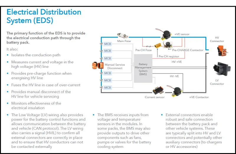
Sofware is a major component of lithium-ion battery packs, particularly for automotive applications. The software is implemented using the Battery Management System (BMS). Control systems are required to keep the cells within their specified operating range and to protect them from abuse. Fuel gauging needs complex algorithms to estimate the state of charge (SOC). Communications with other vehicle systems are needed for monitoring the battery status and controlling energy flows.
5. Internal Inter-connections
Low power cells are usually connected together using nickel strips which are welded to the cell terminals or the case. Soldering is not recommended since the soldering process is bound to apply large, uncontrolled amounts of heat to the battery components which may damage the separators or the vents which are normally made of plastic. Modern computer controlled resistance welders allow much more precise control of the welding process, both limiting the amount of heat applied to the battery and localising the heat to a small desired area. Welding also provides a stronger, low resistance joint. The interconnecting strips often have complex shapes and profiles which may be stamped out of flat strip in a progressive die. High power cells may use solid copper bus bars or braided straps.The electronic components are usually mounted on a conventional printed circuit board (PCB). Flexible PCBs may cost more than rigid PCBs but they can be used to reduce the overall product costs. Not only do they save weight and space but they also provide more packaging options and they simplify physical interconnections and assembly operations as well as eliminating the need for connectors. Connectors may in fact be specified to facilitate assembly and disassembly if the design requires that individual battery components need to be changed or serviced but there is usually a cost and reliability penalty associated with such designs.
6. External Connections
The type of terminals or connections to the external circuits depend on the current to be carried, the frequency with which the battery may be connected and disconnected, and the design of the circuit to which the battery will be connected. For low power circuits, gold plated contacts are the terminals of choice for connectors which are subject to frequent insertions. Gold is hard wearing, it has low contact resistance and doesn't oxidise. Flying leads with spade terminals or snap on studs are also used for low power applications. Metal tabs are also used on pouch cells. Terminals for high power applications are usually threaded metal studs to ensure a reliable connection. Safety requirements on high voltage batteries may also dictate shrouded terminals to prevent accidental exposure of the operator to dangerous voltages of the battery or to short circuits. Keyed terminals or connections are also advisable to prevent connection to incorrect chargers or loads.
7. Thermal Design
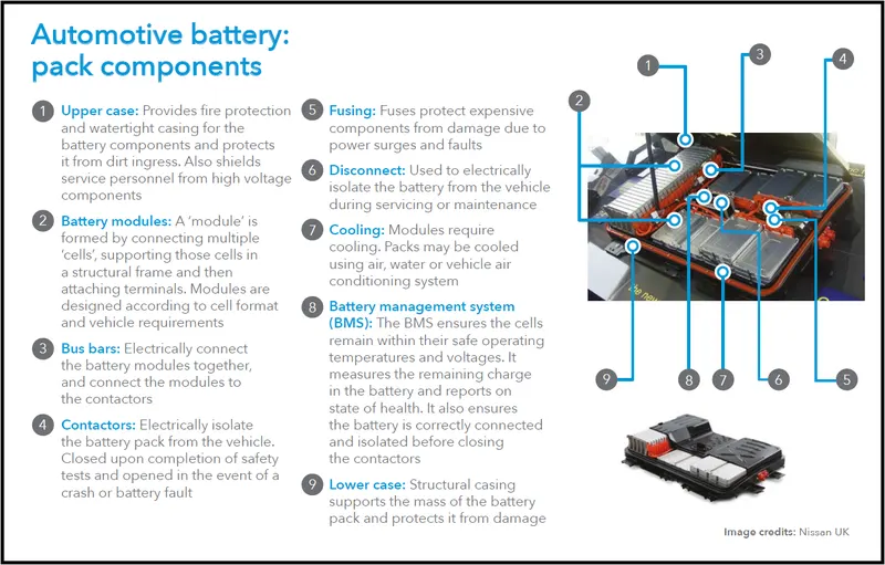
Thermal management is a major issue in high power designs, particularly for automotive applications. As part of the battery system, it may be necessary to provide air or water cooling ducts, pumps or fans and heat exchangers for high temperature working or heaters for operating in low temperature environments. The layout of the cells should be conducive to managing heat flows within the pack.
8. Battery Pack Casing or Housing
The battery casing has to provide the mechanical and electrical interfaces to the product it is designed to power as well as to contain all the components outlined above. The simplest and least expensive packaging for small batteries is shrink wrap or vacuum formed plastic. These solutions are only possible if the battery is intended to be completely enclosed by the finished product. Injection moulded plastics are used to provide more precision packs. For enclosed pack designs using a minimum of materials are based around which a plastic frame holds the components in place thus minimising the cost, the weight and the size of the pack. The overall product cost can be further reduced by using insert mouldings in which the interconnection strips and the terminals are moulded into the plastic parts to eliminate both materials and assembly costs.Overmoulding may also be used to encapsulate and protect small components or sub-assemblies. In some designs the battery pack forms part of the outer case of the end product. These designs are usually required to incorporate a mechanical latch to hold the battery in place. This latch as well as the terminals must interface with plastic parts from a different supplier so high precision and tight tolerances are essential. Acrylonitrile butadiene styrene (ABS) thermoplastics are the materials typically used for this purpose.
Batteries for traction applications are usually very large and heavy and subject to large physical forces as well as vibrations so substantial fixings are required to hold the cells in place. This is particularly necessary for batteries made up from pouch cells which are vulnerable to physical damage. Automotive battery packs must also withstand abuse and possible accidental damage so metal casings will normally be specified. The metal pack casing also serves to confine any incendiary event resulting from the failure of a cell or cells within the battery and to provide a measure of protection for the user. At the same time the case must also protect the cells and the electronics from the harsh operating environments of temperature extremes, water ingress, humidity and vibration in which these batteries work.Usually the complete pack is replaced when the battery has reached the end of its useful life. In certain circumstances however, for instance when the pack incorporates a lot of electronic circuits, it may be desirable to design the pack such that the cells within the pack can be replaced.If the design requires provision for replacement of the cells the casing of the battery pack must be designed to clip or screw together. Normally the parts of the plastic housing will be ultrasonically welded together both for security and for low cost as well as to prevent unauthorised tampering with the cells and the electronics.
Thermal effects need to be taken into account and, tolerances must allow for potential swelling of the cells. Some Lithium pouch cells may swell as much as 10% or more over the lifetime of the cell. For this reason potting is not recommended. In low power designs, groups of pouch cells may be shrink wrapped but for higher power applications plastic or metal frames may be used both to provide physical protection of the cells as well as to allow for swelling.The battery pack should not normally be airtight or sealed since many batteries release hydrogen or oxygen during operation which could cause bursting of the pack or an explosion if the gases are allowed to accumulate. Lithium cells do not emit gases under normal circumstances, but in the case of failure and thermal breakdown, inflammable gases may be vented by the cells. Some form of ventilation or purging should be provided to avoid these problems.
Tolerances should also allow for the use of alternative cells from other manufacturers. While the cells may be "standard" sizes, there could still be differences between cells from different vendors.High power batteries may need special ventilation or channels between the cells to permit forced air or liquid cooling.
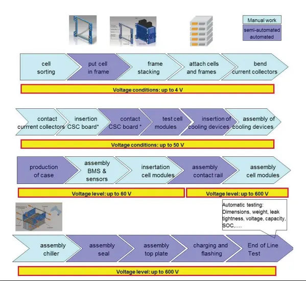
Battery Pack Assembly Line
- PROCEDURE:
- first we have to start with Cell calculation.
- Then we will do Battery Pack assumptions.
- After assumptions, we have to do Battery pack calculations.
- from Cell Dimensions we calculate the surface required for a battery pack.
- Depending upon the above calculations we build Battery Pack construction.
REFERENCES:
- https://skill-lync.com/student-projects/
- https://boldvaluable.tech/blog/custom-battery-pack-design-lithium-cells/
- Calculation of EV battery pack design - https://x-engineer.org/ev-design-battery-calculation/
CONCLUSION:
- Based on the reference and the calculated data, we can choose the suitable battery cells for our electric vehicle battery pack as per the need