Project 1 Mechanical design of battery pack
AIM: To prepare detailed battery pack drawing along with its enclosure with following data.
- Battery pack capacity: 18 kWh
- Cell: ANR26650M1-B
Battery pack design:
A battery consists of one or more electrochemical cells (battery cells) which are converting chemical energy into electrical energy (during discharging) and electrical energy into chemical energy (during charging).
Individual battery cells are grouped together into a single mechanical and electrical unit called a battery module. The modules are electrically connected to form a battery pack.
In this project we are going to calculate the number of cells that need to be connected in series and parallel to get the desired battery pack capacity. We are going to build an enclosure once the battery pack is ready. Here, we are only limiting our study to outline drawing of the battery pack with its enclosure. The structural integrity of enclosure is not discussed here. We are going to assume thickness of strips, enclosure and also some clearance where ever required, these will be mentioned going forward.
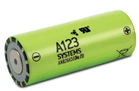
CELL Parameters (ANR26650M1-B )
The data sheet is downloaded from the manufacturer A123-Systems website. Let us now see the cell parameters.
|
ANR26650M1-B TECHNICAL DATA |
|
|
Cell Dimensions |
26 x 65 mm |
|
Cell Weight |
76g |
|
Cell Capacity (nominal/minimum) (0.5C Rate) |
2.5/2.4 Ah |
|
Voltage (nominal) |
3.3V |
|
Internal Impedance (1kHz AC typical) |
6m |
|
Power* |
2600 W/kg |
|
Recommended Standard Charge Method |
2.5A to 3.6V CCCV, 60 min |
|
Recommended Fast Charge Method to 80% SOC |
10A to 3.6V CC, 12 min |
|
Maximum Continuous Discharge |
50A (20C Rate) |
|
Maximum Pulse Discharge (10 seconds) |
120A (48C Rate) |
|
Cycle Life at 20A Discharge, 100% DOD |
>1,000 cycles |
|
Operating Temperature |
-30°C to 55°C |
|
Storage Temperature |
-40°C to 60°C |
Battery pack calculation:
The battery is a cylindrical one with dimensions 26 x 65 mm.
Length/height of the cell = 0.065m
Diameter of the cell = 0.026m
Nominal capacity of the cell = 2.5 Ah
Nominal voltage of the cell = 3.3V

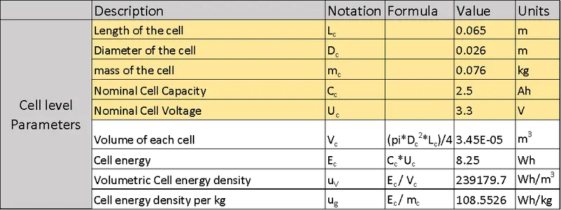
Initially, we have calculated the cell level parameters that will be needed for the battery pack level calculation. Refer attached spreadsheet.
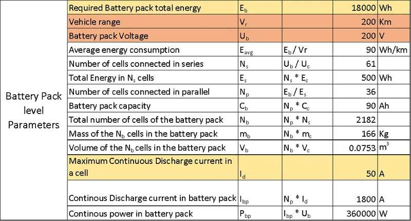
We are designing the battery pack of 18 KWh (as per given input) with an assumed range of 200Km and assumed voltage of 200V.
In the above table we are calculating:
- Average energy consumption: which is total energy of battery pack to the vehicle range.
- Number of cells connected in series: Since we have the battery pack voltage and cell voltage, we can get the number by dividing battery pack voltage by cell voltage. This gives the count of the cells that are connected in one series arrangement or we can say it in one string.
- Total energy in the cells connected in series: is calculated by multiplying number of cells in series with energy of a single cell.
- Number of cells connected in parallel: can be obtained by dividing energy of the battery pack with energy of the cells connected in series. This count tells that 36 such parallel strings are needed; each string contains 61 cells.
- Battery pack capacity: can be obtained by multiplying number of cells in parallel with a single cell capacity.
- Number of cells of the battery pack is obtained by multiplying number of cells in series with parallel.
- Mass of the total cells in the battery pack is obtained by multiplying total number of cells in the pack with a single cell mass.
- Similarly, volume of the total cells can be obtained by multiplying total number of cells in the pack with a single cell volume.
- Continuous discharge current of the battery pack is calculated by multiplying the cell discharge current with number of strings in parallel.
- Continuous discharge power of the battery pack is calculated by multiplying the Continuous discharge current of the battery pack with battery pack voltage.
By the above calculations, we can infer that the battery pack needs 61 cells in series and 36 cells in parallel. This configuration of 61S36P looks scary to build as it needs lot of space and the battery management also becomes complex to manage, hence it needs to be split into battery modules.
Total number of cells in battery pack as per the above calculation: 2182
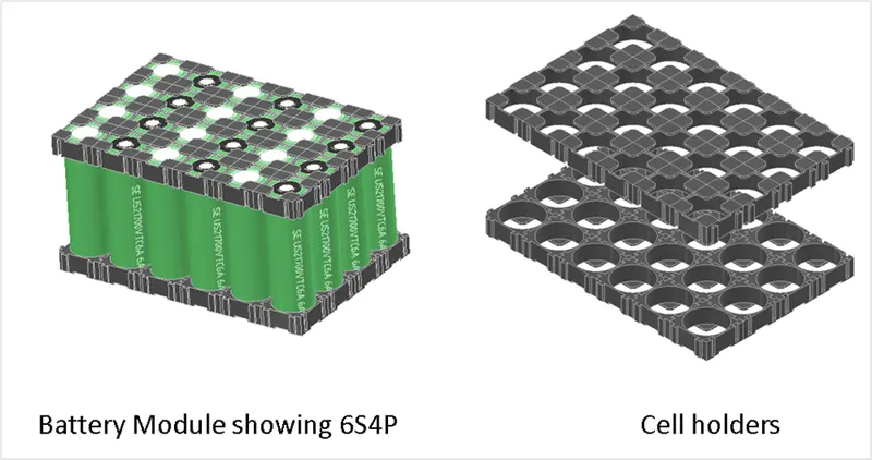
Let us consider a battery module of 6S4P --> This means the number of cells in a battery module shall be 6*4 = 24 cells.
Now, let us calculate the number of battery modules that are needed for this battery pack. It can be obtained by dividing total number of cells in battery pack with total number of cells in a single battery module.
- Number of battery modules = 2182/24 = 90.9 ~ 91 (rounding off)
- Let us now configure these battery modules in series and parallel:
- It can be configured as 13 x 7 = 91
The outline 3D model of battery pack is modelled using Autodesk inventor and the images of the battery module and battery pack with enclosure are shown.
In this model, I have provided some clearances from battery to nearest wall, this is to accommodate Battery management system for each module, nickel strips, insulation, cooling pack which were not considered in this project. Generally, the nickel strips are spot welded on the cells to form a battery module.
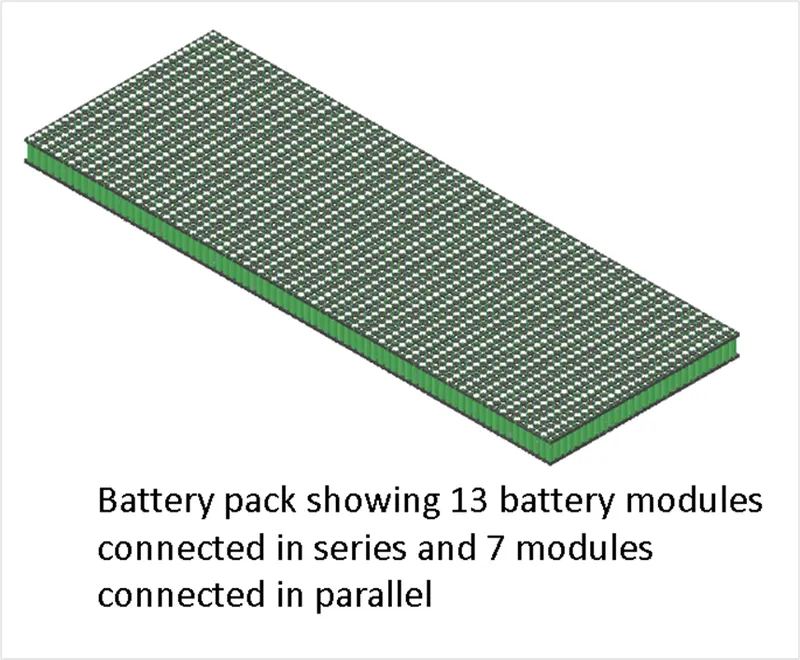
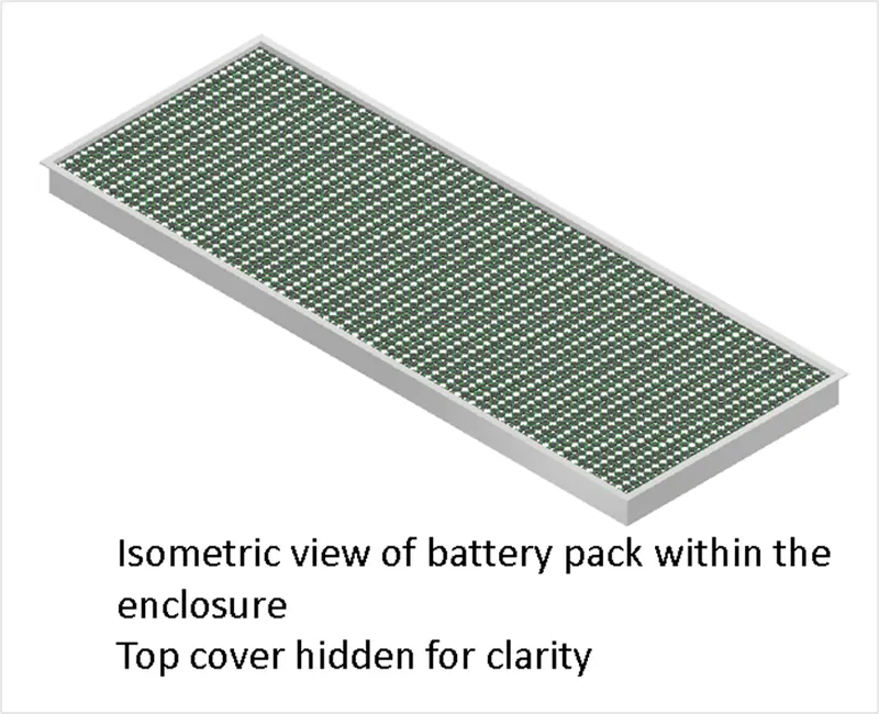
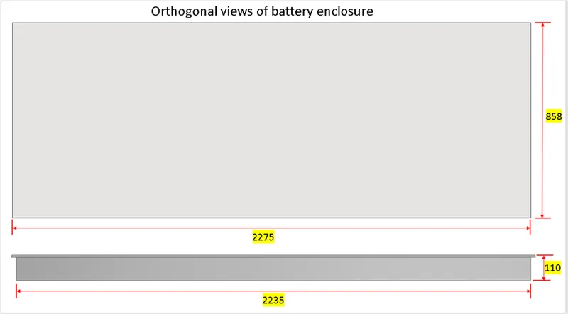
The clearances, wall thickness, overall dimensions of the enclosure are well shown in the images below.
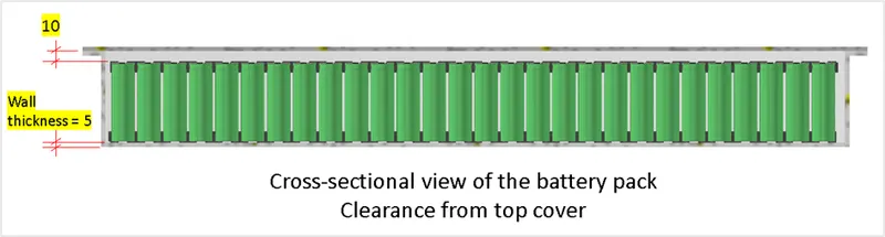
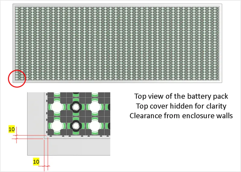
- The battery pack enclosure shown here is just an outline to get a rough idea. The actual enclosure will be designed in such a way that it meets all the functional requirements, of which few are listed here:
- Thermal conductivity
- Structural integrity to withstand the various loads in the actual drive cycle and thermal load from within the battery.
- Mitigating the risk of fire coming out in case of batteries explosion if any.
- Ports for input and output.
Battery Pack dimensions (Length x width x height) = 2.275m x 0.858m x 0.11m
These dimensions are just for representation, in actual the stackup analysis has to be performed to get the correct dimensions and have proper assembly of the components.
Approximate weight of the enclosure, considering aluminium material = 60 Kg, but this is not an optimized one.
Additional weight comes from wiring, BMS, nickel strips, insulation material, cooling equipment, fasteners, Etc.
Structural and thermal analysis results will yield to the optimized design of the enclosure.
The battery packs are generally split into 2 or more parts while designing because it depends on the vehicle overall dimensions, the floor plan of the vehicle and many other aspects. If there is no room to place such a lengthy battery pack, then a cell of higher specifications shall be selected or by using a different shape of the cell (prismatic cells) thereby having a good control on the overall dimensions of the pack.
Conclusion:
Thus, the battery pack is constructed with a capacity of 18KWh , 200V and a range of 200Km. The enclosure outline is also drafted in this projected and the battery pack arrangement can be optimized by playing around with different configurations of battery modules, cell specifications, cell shapes, floor plan of the vehicle, vehicle overall dimensions.
References:
https://www.batteryspace.com/prod-specs/6610.pdf
https://www.electricbike.com/introduction-battery-design-1/